
Parsing Circuit Topology in a Deductive System
Proceedings of the Ninth International Joint Conference on Artificial Intelligence. Expert Systems. Pages 407-409.
© 1985 International Joint Conferences on Artificial Intelligence
Abstract
As a step toward automatic circuit understanding, we have developed a method for parsing circuit topology in a deductive system called Duck. A circuit is viewed as a sentence and its elements as words. Generating circuits with specific functions is represented by deductive rules analogous to definite clause grammars. Using those rules, an object circuit is decomposed into a parse tree of functional blocks in terms of logic programming.
- DeKleer, ]. "Causal and Teleological Reasoning in Circuit Recognition" MIT AI-TR-529, I 979.
- McDermott, D. "Duck: A Lisp-based Deductive System" Dept. of CS, Yale Univ., 1983.
- Pereira, f. and Warren, D. "Definite Clause Gram- mars for Language Analysis" Artificial Intelligence 13 (1980) 231-278.
- Tanaka, T. "Representation and Analysis of Electri- cal Circuits in a Deductive System" Proc. IjCA1-83, Karlsruhe W.-Germany, August 1983, pp. 263-267. IJCAI
- Tanaka, T. "Structural Analysis of Electronic Cir- cuits in a Deductive System" to appear in Com- puter Expert Systems, Leonard Bole ed., Springer- Verlag, 1985.
- "101 Analog IC Designs" Interdesign Inc., Sunnyvale Ca., 197€
References were extracted automatically from the PDF and may contain errors.
Full text extracted automatically from the PDF; figures, tables and equations may differ. The PDF is the version of record.
ABSTRACT
As a step toward automatic circuit understand ing, we have developed a method for parsing circuit topology in a deductive system called Duck. A circuit is viewed as a sentence and its elements as words. Generating circuits with specific functions is repre sented by deductive rules analogous to definite clause grammars. Using those rules, an object circuit is de composed into a parse tree of functional blocks in terms of logic programming.
INTRODUCTION
Electronic circuits are designed as a goal orient ed compositiOn of basic circuits with specific func tions. Therefore, understanding a circuit means finding a hierarchical structure of functional blocks and rediscovering the designer's original intentions. Almost all designed circuits have the features of language which carries information of the speaker's intentions mapped on its structures. In addition, a circuit schematic not only represents a physical circuit, but also functions as a written language for electronic engineers.
We have developed a method for parsing circuit topology in a deductive system called Duck [2]. A circuit is viewed as a sentence and its elements as words. Generating circuits with specific functions is represented by the deductive rules analogous to defi nite clause grammars [3]. Using those rules, an object circuit is decomposed into a parse tree of functional blocks in terms of logic programming. The parsing circuit topology is a step toward automatic circuit understanding.
II REPRESENTATION OF CIRCUITS
A. Circuit and its Elements
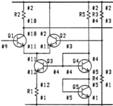
Figure I shows a small portion of an analog IC circuit [6]. We call the circuit CD71. The circuit is represented as follows in our system.
!<(RESISTOR R1 #12 #1) (RESISTOR R2 #2 #10) (RESISTOR R3 #2 #3) (RESISTOR R4 #3 #1) (RESISTOR R5 #2 #4) (NPN-TR Q1 #9 #11 #10) (NPN-TR 02 #3 #11 #2) (NPN-TR 03 #4 #12 #11) (NPN-TR 04 #4 #5 #4) (NPN-TR 05 #5 #1 #5)>"RESISTOR" is a 3-place function in logic. "(RESISTOR R I # 12 #I)" denotes a resistor named R I connecting node # 12 and node #I. The node order is arbitrary
Takushi Tanaka
The National Language Research Institute 3-9-14 Nishigaoka Kita-ku, Tokyo 115, japan
because a resistor does not have polarity. "(NPN-TR Q3 #4 #12 #11) 11 denotes an NPN-transistor named Q3 with the base connected to node #4, the emitter to node # 12, and the collector to node #II respec tively. A circuit is represented by a tuple of those terms surrounded by "!<" and 11 > 11 · The order of the elements in the tuple is not important.
B. Macro Elements
In designing analog IC circuits [6], there are many functional blocks which are viewed as macro elements (macro devices). The macro elements in Figure I, such as "diode-connected transistor", "series circuit of diodes", and "voltage regulator" are repre sented as follows in the parsing process of the circuit.
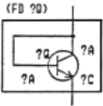
(0-TRANSISTOR (FD 04) #4 #5) (0-TRANSISTOR (FD 05) #5 #1) (S-DIODE (S-OD (FD 04) (FD 05)) #4 #1) (V-REGULATOR (V-REG (S-OD (FD 04) (FD 05)) R5) #2 #4 #1)The term "(D-TRANSISTOR (FD Q4) #4 #5)" denoting "diode-connected transistor" has the same arguments as an ordinary diode. That is, the first argument "(FD Q4)" is the name of the diode. The second is its anode #4, and the third is its cathode #5. "(S-DIODE (S-DD (FD Q4) (FD Q5)) #4 #I)" denotes a series circuit of diodes. A new name "(S-DD (FD Q4) (FD Q5))" is given to the circuit as a macro element. Macro elements correspond to non-terminal symbols, while ordinary elements terminal symbols.
III PARSING CIRCUIT TOPOLOGY
A. Rules for Parsing
In order to find a specific element in a circuit, a membership predicate "MEM-REST" is defined by the following assertion.
"?"-marked symbols are universally quantified varia bles. The notation "!&?X" matches any number of elements of a tuple, binding ?X to a tuple of those elements. So "<!&?L ?M !&?R>" matches any tuple of one or more elements, and binds ?M to a member of the tuple, ?L to the left part, and ?R to the right part of the rest [2). Using the predicate "MEM REST", we can separate an object circuit into an element and the rest:
(MEM-REST element object-circuit rest)
When we want to refer to macro elements in a circuit, we will use a predicate "SUBCT" (sub circuit) similar to "MEM-REST". The difference is that the first argument of "SUBCT" is an abstract element (macro element) rather than a real one. The word "abstract" means that the element does not exist as a member of the tuple representing an object circuit. The abstract element is a sub-circuit with a specific function represented as a macro element:
(SUBCT macro-element object-circuit rest)
A macro element "diode-connected transistor" is defined by the backward chaining rule (1). The rule states that the existence of an NPN-transistor with the base and the collector connected to the same node implies the existence of a diode-connected transistor as an abstract element. The functions "D-TRANSISTOR" and "FD" are introduced as Skolem functions representing the existence of a diode connected transistor and its name.
(<- (SUBCT (D-TRANSISTOR (FD ?Q) ?A ?C) ?CT ?REST) (MEM-REST (NPN-TR ?Q ?A ?C ?A) ?CT ?REST)) (1)
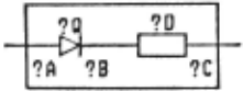
Rule (2) recursively defines "series circuit of diodes" as a macro element. The conjunctive part of the definition says "find a diode-connected transis tor ?Q connected to ? A and ?B in the circuit ?CT", and "find a series circuit of diodes ?D connected to
?B and ?C in the rest of the circuit", the11 "give a name (S-OD ?Q ?D) to the macro element".
(S-DD '?Q ?D>
The following rule enables us to refer to a resistor represented by "(RESISTOR ?R ? A ?B)" or "(RESISTOR ?R ?B ?A)" as "(RES ?R ?A ?B)".
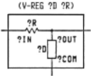
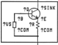
Macro elements such as "voltage regulator" and "current source" are also defined (Figure 4, 5).
(<- (SUBCT (V-REGULATOR (V-REG ?D ?R) ?IN ?OUT ?COM) ?CT ?RT) (AND (SUBCT (S-DIODE ?D ?OUT ?COM) ?CT ?RTl) (SUBCT (RES ?R ?IN ?OUT) ?RTl ?RT))) (<- (SUBCT (C-SOURCE (C-SINK ?VS ?Q ?R) ?SINK ?COM) ?CT ?RT) (AND (SUBCT (V-SOURCE ?VS ?B ?COM) ?CT ?RTl) (MEM-REST (NPN-TR ?Q ?B ?E ?SINK) ?RTl ?RTZ) (SUBCT (RES ?R ?E ?COM) ?RTZ ?RT)))
<C-SINK '?VS '?0 '?R>
B. Parsing Process
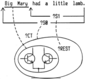
In definite clause grammars [3), a part of a sen tence under processing is represented by two pointers. Each pointer is composed of a list of words occurring after that point in the sentence. The last two argu ments ?CT and ?REST of the predicate SUBCT correspond to those pointers as shown in Figure 6. The parsing process proceeds similarly. The main difference is that the object circuit is not a string of words but a set of elements. Also, every elements has a struc ture representing the circuit topology.
I
feeding in the following goal causes Duck to start parsing. "cd71" stands for the tuple of CD71.
As the last argument of the predicate SUBCT is substituted by a null circuit "!<>", the goal asks whether the total circuit CD71 pictured in Figure I is a macro element "comparator with internal voltage reference". The comparator is defined as a conjunction of two sub-goals: "single-ended differential amplifier", and "voltage source" for reference. "differential ampli fier" is defined as a conjunction of "emitter-coupled pair", "current source", and a resistor for load. "volt age source" is defined by either "voltage regulator" or "voltage divider" as disjunctive sub-goals. These goals are searched in top-down depth-first manner. The initial goal {3) succeeds, and we can eventurally acquire values for the variables:
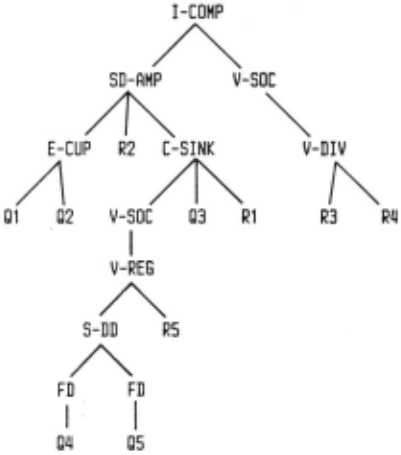
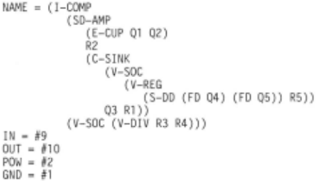
The name of the macro element keeps track of succeeded goals. It forms a hierarchical structure of macro elements and can be viewed as a parse tree for the circuit corresponding to the syntactic structure of a sentence (Figure 7).
C. Behavior of "SUBCT"
Functional blocks in analog IC designs are coded into deductive rules. The rules define a set of circuits in the same way that generative grammars define a language. If the object circuit is given, and if the circuit is a member of the set, the following goal parses the circuit.
(SUBCT ?WHAT-CIRCUIT object-circuit !<>)
In this case, the top-down mechanism does not work efficiently, because the first argument does not have information about how to parse the circuit. Duck tries the rules one after another until the rest part of SUBCT becomes a null circuit !<>, This parsing mech anism works effectively when a circuit goal is given such as (3).
Even if an object circuit is not a wer.1ber of the set, if the null circuit !<> is replaced by a variable ?REST, the goal can identify all functional blocks which are defined as macro elements in the circuit.
As a consequence of its realization in logic programming, data flows to the predicate SUBCT are bilateral. If a macro element is given instead of the object circuit, the following goal works as a circuit generator. We can then acquire the generated circuit from the variable ?CT.
IV ELECTRICAL CONDITIONS
A. Transferring Conditions between Goals
A "voltage divider" is defined by a pair of re sistors "(V-DIV ?X ?Y)" as shown in Figure 8. Duck finds ten voltage dividers in the circuit of figure I according to the definition, but eight of them such as "(V-DIV Rl R4)" are not intended as voltage divid ers. These undesired interpretations do not form macro elements which contribute to the goal of total circuit, so they are to be rejected in the parsing process. If we are informed that #I and #2 are power nodes con nected to the power supply, we can rejec t undesired interpretations more efficiently. That is, we can use an electrical condition which states that the node ?OUT of a voltage divider must not be connected to power nodes.
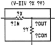
The electrical conditions are not only used as inputs for identifying a macro element, but also used as outputs. If "voltage regulator" is identified in a circuit, we can assume that the input node ?IN and the common node ?COM of the voltage regulator must be power nodes. Those assumptions are used afterward in identifying another macro element such as a voltage divider efficiently. In order to transfer the information between goals, we will introduce new variables "?IN COND" and "?OUT -COND" to form a new predicate "SUBCTC" (sub-circuit with conditions).
We will also re-define "voltage regulator" using this predicate:
(<- (SUBCTC (V-REGULATOR (V-REG ?D ?R) ?IN ?OUT ?COM) ?CT ?REST ?IN-COND ?OUT-COND) (AND (SUBCT (S-DIODE ?D ?OUT ?COM) ?CT ?RTl) (SUBCT (RES ?R ?IN ?OUT) ?RTl ?REST) (NONMEMBER (POWER-NODE ?OUT) ?IN-COND) (= ?OUT-COND !<(POWER-NODE ?IN) (POWER-NODE ?COM) !&?IN-COND>)))B. Context-dependent Circuit Generation
Suppose that a goal generates two conjunctive sub-goals and each goal generates a voltage source in designing circuits. When one of the voltages is derived from the other, an engineer may combine two voltage sources into one voltage source for sim plicity. That is, he has the ability to use context dependent circuit generation rules, while we have developed the rules corresponding to context-free grammars.
Using the predicate SUBCTC, we can overcome the problem of combining circuits. When a subgoal finds a voltage source, the subgoal generates informa tion pertaining to the voltage source as an electrical condition and transfers the information to another subgoal which needs a voltage source. Then the sub goal succeeds by the transferred conditions instead of finding another voltage source.
C. Rules for Combined Circuits
We will define the voltage source using the predicate SUBCTC, so that it generates a term "(CTRLD-VOL TAGE (V-SOC ?V) ?OUT ?COM)" as c.n electrical condition for the output. The condition states that the voltage across ?OUT and ?COM is controlled by the voltage source "{V-SOC ?V)". If the goal succeeds, the rest of the circuit no longer contains the voltage source, but the ?OUT -COND
contains the electrical condition term for another goal which needs a voltage source. Using this condi tion, we can define a current source which shares its voltage source with another circuit.
V CONCLUSION
An electronic circuit is designed as a goal oriented compositiOn of functional blocks. Therefore, if a circuit goal is given, the goal contains the infor mation needed to read the circuit. The top-down mechanism effectively analyzes an electronic circuit according to the goal. The parsing circuit topology is a step toward automatic circuit understanding similar to syntactic analysis of language. But, circuit understanding implies more than language understand ing; unlike language, a circuit not only represents designer's intentions, but also represents the physical circuit itself.
We have tacitly employed a closed world assump tion on circuit topology. That is, no element or device exists without being explicitly included in the circuit tuple. However, the closed world assumption is no longer appropriate for a tuple of electrical conditions. The tuple represents only a small portion of the electrical properties of an object circuit. If a specific term is not found in the tuple, we can not conclude that the circuit does not have the electrical property denoted by the term. Negative information on electri cal conditions must be explicitly mentioned in an open world assumption.
The electrical conditions define the relationship between a circuit topology and its electrical charac teristics. We can introduce more terms relating to electrical behavior to the definitions of functional circuits. We may introduce terms of the form "( < q p)" in which "p" and "q" specify electrical behavior. When a circuit goal succeeds, the argument ?OUT COND of the predicate SUBCTC contains . rules of electrical behavior for the circuit. We are now in the process of developing such rules.
ACKNOWLEDGMENTS
I would like to thank: Prof. Drew McDermott for Duck, !sao Nagasawa and David Littleboy for their helpful advice, and AI-circle AIUEO for discussions.
@inproceedings{ijcai1985p77,
  title     = {Parsing Circuit Topology in a Deductive System},
  author    = {Tanaka, Takushi},
  booktitle = {Proceedings of the Ninth International Joint Conference on
               Artificial Intelligence, {IJCAI-85}},
  publisher = {International Joint Conferences on Artificial Intelligence},
  editor    = {Aravind Joshi},
  pages     = {407--409},
  year      = {1985},
  note      = {Expert Systems},
  url       = {https://ijcai.org/proceedings/1985/77},
}
TY - CPAPER TI - Parsing Circuit Topology in a Deductive System AU - Tanaka, Takushi T2 - Proceedings of the Ninth International Joint Conference on Artificial Intelligence, IJCAI-85 PB - International Joint Conferences on Artificial Intelligence PY - 1985 SP - 407 EP - 409 UR - https://ijcai.org/proceedings/1985/77 ER -Copied
Machine-readable versions of this paper, for tools and AI agents:
 Welcome
 Future Conferences
 AI Journal Division
 IJCAI Proceedings
 About IJCAI
 IJCAI Awards