
Representation and Analysis of Electrical Circuits in a Deductive System
Proceedings of the Eighth International Joint Conference on Artificial Intelligence. Expert Systems. Pages 263-266.
© 1983 International Joint Conferences on Artificial Intelligence
Abstract
We have developed representations and analysis methods for electrical circuits in a deductive system called DUCK.** Circuits are represented as conjunctions of logical predicates. Circuit analysis is done as an iteration of proofs which determine the basic structures in the circuit. · Electrical constraints for the circuit are produced from the results of the proofs. The constraints are then solved using propagation methods.
- Brown,A. "Qualitative Knowledge, Causal Rea- soning, and the Localization o f Failures" M.I.T. AI-TR-362, 1977
- Charniak,E., Riesbeck,C., McDermott, D. "Artifi- cial Intelligence Programming" Lawrence Erlbaum Association, 1980, NJ.
- DeKleer ,J. "Causal and Te l e ological Reasoning in Circuit Recognition" M.I.T. AI-TR-529, 1979
- DeKleer ,J. "The origin and Resolution of Ambi- guities in Causal Arguments" IJCAI-79, 1979 IJCAI
- Doyle,J. "A Truth Maintenance System" Artifi- cial Intelligence, vol.l2, 1979
- McDermott,D. "Circuit De sign as Problem solving" Artificial Intellige nce and Pattern Recognition in Computer Aided Design, Latombe ed. IFIP, North-Holland, 1978
- McDermott,D. "Non Monotonic Logic I I : Non- Monotonic Modal Theories" Research Report #174, Dept. of Computer Science, Yale Univ. , 1980
- McDermott,D. "DUCK: A Lisp-based Deductive System" Dept. of Computer Science, Yale Univ. 1982
- McDermott,D., Charniak,E. "Introduction to Artificial Intellige nce" unpublished manuscript
- Nilsson,N.J. "Problem-solving Methods in Ar- tificial Intelligence" McGRAW-Hill, 1971
- Nilsson,N.J. "Principles of Artificial In- telligence" Tioga Pub., Palo Alto, 1980
- Stallman,R.M. ,Sussman,G.J. "Forward Reasoning and Dependency -Directed Back-tracking in a Sy stem for Computer Aided Circuit Analysis" Artificial Intelligence, vol.9, 1977
- Sussman,G.J., Stallman,R.M. "Heuristic Tech- nique in Computer-Aided Circuit Analysis" IEEE Trans. Circuit and Systems, vol.CAS-22,No.ll,l975
- Sussman,G.J. "SLICES At the Boundary Between Analy sis and Synthesis" Artificial Intelligence and Pattern Recognition in Computer Aided Design, Latombe ed., IFIP, North-Holland, 1978
- 15J Sussman,G.J.,Steele,G.Jr "Constraints: ALan- guage for Expressing Almost-Hierachical Oeser ip- tions" Artificial Intelligence, vol.l4, 1980
- Tanaka,T. "Simulation of Thinking Process on Electronic Circuits in Natural Language I, II, III", Technology Report of Kyushu Univ. vol.44,45, 1971, 1972 (Japanese)
- Tanaka,T. "Pattern Directed Circuit Recogni- tion I,II" 23rd & 24th Covention of Information Processing Society in Japan, 1981,1982 (Japanese)
References were extracted automatically from the PDF and may contain errors.
Full text extracted automatically from the PDF; figures, tables and equations may differ. The PDF is the version of record.
REPRESENTATION AND ANALYSIS OF ELECTRICAL CIRCUITS IN A DEDUCTIVE SYSTEM
Takushi Tanaka
Artificial Intelligence Project Department of Computer Science, Yale Univer s ity Box 2158 Yale Station New Haven, CT06520 U.S.A.
The National Language Research Institute 3-9-14 Nishigaoka Kita-ku, Tokyo 115 Japan*
object circuit, it is executed as a meta procedure outside of the deductive system. If a specific structure is found in the object circuit, local electrical constraints for the specific structure are translated into global constraints on the object circuit using the results of the proof. The constraints are solved by means of propagation methods. [12)
II REPRESENTATION OF CIRCUITS
A. Predicates for elements and circuits
The circuit CA12 of Figure 1 is represented as follows (1) in the DUCK system. [8) The proposition "(TERMINAL Tl #1)" states that Tl is a terminal at node #1. The proposition "(RESISTOR Rl #1 #2)" states Rl is a resistor connecting node #1 and node #2. The node order is important for elements or devices which have polarity, such as diodes. So we define the predicate "DIODE" such that "(DIODE Dl #2 #3)" states Dl is a diode with the cathode connected to node #2 and the anode to node #3. Now we can also define the predicate "TRANSISTOR" like "DIODE". "CA12" is a predicate without arguments. "(CA12)" as a propositional constant states that there is a circuit called CA12. "->" is the forward chaining symbol. It means logical implication, but procedurally, it means that woen "(CA12)" is added to the database of axioms, then "(TERMINAL Tl #1)", "(TERMINAL T2 #2) ", ... , "(DIODE Dl #2 #3)" are to be asserted (added to the database) immediately. [8), [9)
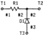
Figure 1: Circuit CA12
(RULE CIRCUIT-LIBRARY-CA12
(CA12) -) (AND (TERMINAL Tl #1)
(TERMINAL T2 #2)
(TERMINAL T3 #3)
(RESISTOR Rl #1 #2)
(DIODE Dl #2 #3))) -------(1)
ABSTRACT
We have developed representations and analysis methods for electrical circuits in a deductive system called DUCK.** Circuits are represented as conjunctions of logical predicates. Circuit analysis is done as an iteration of proofs which determine the basic structures in the circuit. ·Electrical constraints for the circuit are produced from the results of the proofs. The constraints are then solved using propagation methods.
I INTRODUCTION
When an expert first looks at a circuit schematic, he tries to partition the circuit into familiar sub-circuits with known goals. He then tries to pursue the causality of electrical events through those sub-circuits to determine if and how it achieves the overall goal of the circuit. This is based on his assumption that every electronic circuit is designed as a goal oriented composition of basic circuits with known goals. Even in the analysis of an electrical circuit with an unknown goal, although we could perform a formal numerical analysis of the full circuit equations, we try to discover specific sub-structures, such as series or parallel circuits, in order to rewrite the circuit into a simpler one. In many cases we can analyze circuits without formal numerical analysis.
Using a deductive system, we have implemented the process which determines these specific structures in a circuit. Circuit elements and devices are represented as logical predicates which have · element names and connecting nodes as terms. A circuit is represented as a conjunction of propositions which represent each electrical element or device. The process of determining a specific structure in the object circuit is realized as a proof of a predicate bound by existential quantifiers representing the existence of the specific structure. Since the trans formation of a circuit into an equivalent one involves changing the axioms which represent the
* present address
** DUCK is a set of LISP routines which implement a relational database similar to those found in AI language such as PLANNER and Prolog. [8)
B. Rules for non-polar elements
If the proposition "(CA12)" is asserted, we can prove the proposition "(RESISTOR Rl #1 #2) ", but we cannot prove the proposition "(RESISTOR Rl #2 #1)". Since we want to have "(RESISTOR Rl #1 #2 )" imply "(RESISTOR Rl #2 #1)", we will assert the following rule (2).
"?X", "?#A", and "?#B" means that variables "X", "#A", and "#B" are bound by universal quan tifiers (skolemization). If "(RESISTOR Rl #1 #2)" is asserted, then "(RESISTOR Rl #2 #1)" will be asserted immediately. Similar rules are written for the predicates "CAPACITOR" and "INDUCTOR".
(RULE RESISTOR-IMAGE
(RESISTOR ?X ?#A ?#B) ->
(RESISTOR ?X ?#B ?#A)) ---(2)
c. Predicates for abstract elements
We can define predicates for abstract elements from atomic formulae representing circuit elements and devices using logical connectives and quantifiers. These predicates correspond to the conceptual hierarchy of circuit elements and devices. First we will define the predicate "Z ELEMENT", so that we can call resistors, capaci tors, and inductors impedance elements (3). The backward chaining symbol "<-" is used insted of the forward chaining symbol. It also means logical implication, but differs proceduraly from forward chaining. The rule (3) is applied when the system tries to prove "(Z-ELEMENT Dl #2 #3)" correspond ing to the question "Does there exist Dl an imped ance element connecting node #2 and #3?". In order to prove the proposition, the system tries to prove either "(RESISTOR Dl #2 #3)" or "(CAPACITOR Dl #2 #3)" or "(INDUCTOR Dl #2 #3) ". We can also define predicates such as "ACTIVE-ELEMENT", "LINE AR-ELEMENT" , ··. , "ANY-ELEMENT" so that we can refer to these classes of elements and devices .
(RULE IMPEDANCE-ELEMENT
(Z-ELEMENT ?X ?#A ?#B) <
(OR (RESISTOR ?X ?#A ?#B)
(CAPACITOR ?X ?#A ?#B)
(INDUCTOR ?X ?#A ?#B))) - (3)
D. Predicates for circuit identification
In order to decide which kind of analysis can apply to the object circuit, several predicates for circuit identification are defined . They iden tify the global properties of the object circuit. By proving the proposition " (EXIST (X #A) (TERMINAL X #A))", we can decide whether the object circuit is an open circuit with terminals which are con nected to other circuits or not. So we can define the predicate "OPEN-CIRCUIT" as follows (4).
"IMPEDANCE-CIRCUIT" ( section IV) is defined to prove that all the elements in the circuit are impedance elements. Predicates such as "TWO TERMINAL-CIRCUIT" which count the number of termi nals are defined using the built-in predicate "TOTAL" (section III).
(RULE CT-IDENTIFIER-OPEN-CIRCUIT
(OPEN-CIRCUIT)<- (TERMINAL ?X ?#A)) ------(4)
ill FINDING A SPECIFIC STRUCTURE IN A CIRCUIT
A. Representation of a specific structure
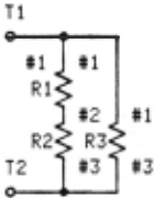
Let us consider the slightly more complicated circuit CA39 in Figure 2. In order to show the existence of a series circuit, we attempt to prove the following formula:
(EXIST(X Y #A #B #C) (AND(RESISTOR X #A #B)
(RESISTOR Y #B #C))) --(5)
When "(CA39)" is asserted , proposition (5) becomes true , because we can substitute constants (Rl R2 #1 #2 #3) into variables (X Y #A #B #C) re spectively, corresponding to the actual existence of a series circuit in CA39. But we can also sub stitute constants (Rl Rl #1 #2 #1) or (Rl R3 #2 #1 #3) to the variables which do not correspond to series circuits. In order to reject the former incorrect substitution, the predicate "(NOT(= #A #C)" is added to (5).
Rejection of the latter incorrect substitu tion is rather difficult. A series circuit demands that the central node '~#B" in (5) should not be connected to elements other than those in the formula. In order to represent this constraint the predicates "DEGREE" and "CONNECTED" are introduced.
B. Rules for node degree
We will use the backward chaining rule "CON NECTED" to enumerate the terminals, impedance elements and diodes X connected to node #A.
(RULE CT-STRUCTURE-CONNECTED
(CONNECTED ?X ?#A) <-
(OR (TERMINAL ?X ?#A)
(Z-ELEMENT ?X ?#A ?#B)
(DIODE ?X ?#A ?#B)
(DIODE
?X ?#B ?#A))) --- (6)
The predicate "DEGREE" has two arguments. It becomes true if the first one is a node and the second one is its degree in lhe object circuit represented in the database of axioms. "DEGREE" is defined as follows using "CONNECTED" and "TOTAL".
(RULE CT-STRUCTURE-DEGREE
(DEGREE ?#A ?#DEG) <-
(TOTAL ?#DEG l(CONNECTED ?X ?#A))) -(7)
"TOTAL" is a special built-in predicate which states that the first term is a sum of the second term according to all known instances of the third term. Now we can define the predicate "R-SERIES" which states the existence of a series-resistor circuit in the object circuit as follows.
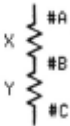
(RULE CT-STRUCTURE-R-SERIES (R-SERIES ?X ?Y ?#A ?#B ?#C) <- (AND (RESISTOR ?X ?#A ?#B) (RESISTOR ?Y ?#B ?#C) (NOT (=?#A ?#C)) (DEGREE ?#B 2))) ---------(8)c. Circuit structures for AC-analysis
We can define predicates for a schematic AC analysis using series, parallel, star, and delta circuit transformations. The predicate "Z-SERIES" for a series circuit of impedance elements is defined by replacing "RESISTOR" with "Z-ELEMENT" in (8). Using the predicate "Z-ELEMENT", predicates "Z-PARALLEL", also defined. "Z-STAR", and "Z-DELTA" are
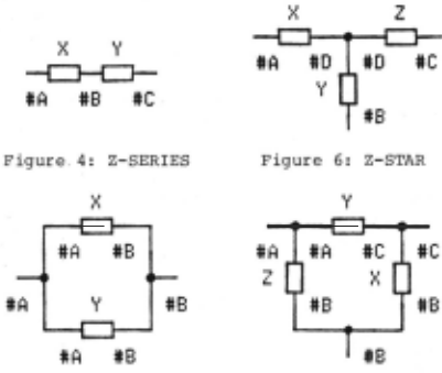
Figure 7: Z-DELTA
IV META PROCEDURES FOR THE DEDUCTIVE SYSTEM
A. Procedurally defined predicates
There are some circuit predicates which can not be adequately represented by the methods dis cussed so far. One such class is the procedurally defined circuits such as "SERIES-PARALLEL-CIRCUIT" or "MULTIPLE-RECTIFIER-CIRCUIT" which refer to an infinite, recursive set of circuits. Another class is composed of electronic circuits with specific goals, such as "PM-RECEIVER". In the definition of a predicate, the way in which an FM-receiver cir cui.,_t; is constructed from sub-circuits (i.e. RF amplifier, ··· , discriminator) to achieve the final goal of the circuit must be included. The former predicates will be developed in the follow ing paragraphs, but the latter predicates have not yet been developed.
The procedure to determine whether a circuit is a series-parallel circuit of impedance elements or not is as follows. First the circuit is iden tified as a two terminal circuit and an impedanc'e circuit. Then the circuit is rewritten iteratively into simpler equivalent forms each time a series or a parallel circuit is found in it. If the cir cuit can ultimately be rewritten into a single element, then we have shown that . the original .of!~
was a series-parallel circuit. The first and last steps are realized using the predicates "TWO TERMINAL-CIRCUIT", "IMPEDANCE-CIRCUIT" and "HAS ONE-ELEMENT" in section III. But the middle step is not so easy to implement in a deductive system, because rewriting a circuit into an equivalent one means changing the set of axioms representing the circuit. This can be done by introducing a state term into each predicate, [10] But it is easier to consider the procedure in a total system consisting of the deductive system and a meta procedure.
B. Rewriting a circuit
In order to control the deductive system pro cedurally, several mechanisms are provided for calling DUCK from LISP. If (9) is evaluated in LISP, the proposition "(CA39)" is added to the DUCK database. Then by the forward chaining rule of CIRCUIT-LIBRARY-CA39, "(TERMINAL Tl #1)", ··· , "(RESISTOR R3 #1 #3)" are added into the database. Then by the forward chaining rule of RESISTOR IMAGE, "(RESISTOR Rl #2 #1) ", ··. , "(RESISTOR R3 #3 #1)" are also added.
Under this condition let us consider a proce dure "R-SERIES-TRANSFORM" which finds a series resistor circuit and then rewrites that part of the circuit into an equivalent element. At first, corresponding to a proof of the proposition "(EXIST (X Y #A #B #C) (R-SERIES X Y #A #B #C))", the following (10) is evaluated in LISP. If series circuits are found, it returns a stream of instances for the variables (X Y #A #B #C).
In order to rewrite a series part, we have to remove the set of axioms corresponding to the series circuit. If the first instance is (Rl R2 #1 #2 #3), (11) and (12) are evaluated.
(ERASE I (RESISTOR Rl #1 #2)) -------------- (11) (ERASE I (RESISTOR R2 #2 #3)) -------------- (12)When (11) is evaluated, not only "(RESISTOR Rl #1 # 2) " but also its deduced image " (RESISTOR Rl #2 #1)" is erased from the database by a data dependency mechanism. [5]
If (13) is evaluated insted of (11) when the first instance is ( R2 Rl #3 #2 #1 ) , then "(RE SISTOR Rl #2 #1)" will be erased but its original "(RESISTOR Rl #1 #2)" can not be erased. As we want to erase the original when the image is erased, we can set up "IF-ERASED-DEMON" in DUCK as a forward chaining from the erasure. The rule is written as follows (14). According to the rule, "(RESISTOR Rl #1 #2)" is to be erased by (13).
(LISPRULE R-IMAGE-DELETE (RESISTOR ?X ?#B ?#A) -) (IF-ERASED I (RESISTOR ?X ?#B ?#A) (ERASE I (RESISTOR ?X ?#A ?#B)))) ---(14)The proposition representing an equivalent resistor is to be added as follows.
(ADD I (RESISTOR ERl #1 #3)) ----------------(15)C. LISP functions for AC-analysis
Now we can define the LISP function "Z-SP CIRCUIT" which can dete rmine whether the object circuit is a series-parallel circuit of impedance elements or not as follows.
(DE Z-SP-CIRCUIT (OBJ-CT)
(AND (PROVE ' (TWO-TERMINAL-CIRCUIT) OBJ- CT) (PROVE ' (IMPEDANCE-CIRCUIT) OBJ- CT) (Z-SP-CIRCUITl OBJ-CT))) ------------(16) (DE Z-SP-CIRCUITl (OBJ-CT ) (AND OBJ-CT (OR(PROVE '(HAS-ONE-ELEMENT) OBJ-CT) (Z-SP- CIRCUITl(Z- SERIES-TRANSFORM OBJ-CT )) (Z-SP-CIRCUITl( Z-PARALLEL-TRANSFORM OBJ-CT] ------------(17)As we can define multiple databases of axiom sets (data pools) in DUCK, the original circuit and all the rewritten circuits for working are stored in separate data pools (see DUCK manual). The variable "OBJ-CT" in (16) and (17) is the name of the data pool which contains the ci rcuit being processing . The LISP function "PROVE" corresponds to "FETCH" in a data pool. The LISP functions "Z-SERIES-TRANSFORM" and "Z-PARALLEL-TRANSFORM" return the name of the new data pool which contains the rewritten circuit, if they succeed in transforming the circuit, otherwise NIL . Finally we have defined the predicate "Z-SERIES-PARALLEL CIRCUIT" by ca lling the LISP function " (Z-SP CIRCUIT 'POOLl) " from DUCK.
The electrical constraints on the object circuit are produced as a side effect of "z SERIES-TRANSFORM" and "Z-PARALLEL-TRANSFORM".
We can define a more convenient predicate "Z SERIES-PARALLEL-STAR-DELTA-ANALYTICAL-CIRCUIT" for actual AC-analys i s adding "(Z-STAR-TRANSFORM OBJ CT)" and "(Z-DELTA-TRANSFORM OBJ-CT)" to (17). It can analyze most two-termina l impedance circuits which e lectrical engineers meet daily.
V SCHEMATIC CIRCUIT ANALYSIS
If we asser t "(CA55)" in Figure 8 as the object circuit, when we try to prove the proposi tion " ( Z-SERIES-PARALLEL-STAR-DELTA-ANALYTICAL CIRCUIT) ", the LISP function "Z-SPYD-CIRCUIT" associated with the proposition is evaluated .
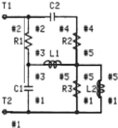
#1
Figure 8: Circuit CA55
After identifing the circuit as a "TWO TERMINAL-CIRCUIT" and an "IMPEDANCE-CIRCUIT", the LISP functions "Z-SERIES-TRANSFORM", "Z DELTA-TRANSFORM" are evaluated iteratively . Those functions try to prove the propositions "(Z-SERIES ?X ?Y ?#A ?#B ?#C)", ··· , "(Z-DELTA ?X ?Y ?Z ?#A · ·· ) " respectively . At the end of thi s procedure , the following list (18) is acquired.
*PREDICRTE-VRRIRBLE- VRLUE* =<<Z-SERIES CNX EZI><WC ~2><~8 ~4><~R ~S><Y C2><X R2>> <Z- PRRRLLEL <NX EZ2><HB HI >< ~R ~S><Y L2HX R3)) <Z-STRR <NX EZ3><NY EZ4>CNZ EZS >C HD HS>CHC H3> CUB H2>CHR Hl>CZ Ll )(Y EZ I )( X EZ2» CZ-PRRRLLEL CNX EZ6>CHB U2>C HR ~3)(Y Rl )(X EZ3» CZ-PRRRLLEL CNX EZ7>CHB H3><~R ~I ><Y [ I ><X EZ4)) CZ-SERIES CNX EZB><HC ~2)(~8 ~3><HR ~~ ><Y EZ6>CX EZ7>> <Z-PRRRLLEL CNX EZ9><~B ~2 lC HR Hl ><Y EZS>CX EZB>>> - - - ------- (18>The first line shows , at first the propos i tion "(Z-SERIES ?X ?Y ?#A ?#B ?#C)" was satisfied by the bindings in the following a ssociation li s t. "(NX EZl)" shows that the new name "EZl" was assigned to the equi val ent element NX .
The following electrical constraints (19) are provided for a series- impedance circuit. "X" and "Y" represent impedances of element s X and Y respectively. "NX" represents the equiva l ent im pedance o f a series circuit. "#A", "#B", and "#C" represent e l ectrical potentials of node #A , #B, and #C (see Figure 4). The symbols representing e l ements in the constraints mean their impedances. The symbols representing nodes mean their e l ec trical potent ials . "C+", "C-", "C*", and "C// " are defined as arithematic operators on complex numbers.
CCC= NX CC+ X Y>> CC= HB ([1/([t([* HR Y)([* H[ X))([t X Y) ))) - --- - (19)According to the list (18 ), each local con straint provided for t he basic s tructures are trans lated into global constrain.ts ori the object circuit, and the following list (20 ) is acquired .
*DBIJECT- CIRCUIT-CONSTRAINTS* = CCC= EZI CC+ R2 C2>> CC= H4 ([1/([t([* HS C2>CC* H2 R2>><C+ R2 C2>>> CC= EZ2 CCII([* R3 L2> <C+ R3 L2>>> CC= EZ3 ([IICCHC* EZ2 EZI ><C* EZI Ll >CO Ll EZ2>>EZ2>> CC= EZ4 ([II(CHC* EZ2 EZI ><C* EZl L1 ><O Ll EZ2>>EZ1 >> CC= EZS ([II CCHC* EZ2 EZ I ><O EZl Ll lCO L1 EZ2>>LI>> CC= HS ([II([HC* EZI Ll HI ><C* Ll EZ2 «2> <C* EZ2 EZ I H3>> CCHC* EZ2 El l >CC* EZI L1 >CO L1 EZ2>>>> CC= EZ6 CCII([* EZ3 Rl >CC+ EZ3 Rl >>> CC= EZ7 ([II([* EZ4 Cl ><C+ EZ4 Cl >>> CC= EZB <C+ EZ7 EZ6>> CC= H3 ([1/([t([* HI EZ6)C[* H2 EZ7>>CC+ EZ7 EZ6>>> CC= EZ9 ([//([* EZB EZS>CC+ EZB EZS>>>> ------- ----(20>The LISP function "PROPAGATE" solves t hese constraints. Here "C+" is analogus to "SETQ" in LISP. At each qonstraint, if all the variables in the right hand side become defined , it is evalu ated and the left hand variable is assigned that value and the cons traint is the n removed from the li s t. This procedure is iterated until the right hand sides cease to fir e . Suppose each element of CA55 has following value (21). Units a r e ohm, farad, and henry respectively. If 10 (volt) 60 (hertz) AC voltage is applied between t erminal Tl and T2, potentials of node #1 and #2 are set as (22), and impedance of each element at 60 (hertz) is also computed and set as (23).
After the evaluation of the LISP function "PROPAGATE", the following answers (24) are ac quired.
| *ELEMENT - VALUE* = ((R1 10.0HR2 20.0 )(R3 30.0)([1 0.0001 J <C2 0.0002)(L1 1.0H L2 2.0JJ ------------ ------- <21 J *POTENTIALS*= <<H2 (10 . 0 0.0JJ<H1 <0.0 0.0) )) - ---<22) |
| *ELEMENT- IMPEDANCES* « R 1 < 1 0. 0 0. 0)) < R<! < 20 . 0 0. 0 J )( R3 < 30. 0 0. 0 J J <C1 <0.0 -26.52576))([2 (0.0 - 13. 26288)) <L1 <0.0 376.92"2»<L2 <0.0 753 .984})) ----------<23 > |
| *COMPUTED-IMPEDANCES - POTENTIALS* « EZ1 <20.0 - 13 . 26288JJ<EZ2 <29 .95258 1.1 9 1773>> <EZ3 <196.6667 608.4257JJ<EZ4 <-245.6987 756.9814)) <EZ5 (48.96205 - 13 .70207JJ<EZ6 <9.949947 .1473568>> <EZ7 <-.2889358 -27.38829JJ<EZ8 <9.661011 -27.24093)) <EZ9 <12.88425 - 16.011 24JHH3 <8.89739 -3 . 26 153 1 )) <H5 <5.402148 1.524807)J<H4 (9.297949 2.583477)) ) - - ------ - - - ( 2ll) |
VI CONCLUSION
We have developed a representation for elec trical circuits using conjunctions of predicates, and realized the procedure of determining circuit structures as proofs. AC and multiple-rectifier analysis were done to confirm the effectiveness of this method. The structures to be found in the analysis were rather simple ones, and the object circuits were restricted to iterations of those structures.
We plan to develop this method to analyze more complicated electronic circuits with specific goals. For those circuits we have to introduce many predicates referring to circuit goals and device-element goals such as "RF-AMPLIFY", "FRE QUENCY-CONVERT", "RF-BYPASS", "DC-BLOCK". The rep resentation of a goal structure for the circuit is as important as the representation of the circuit itself. Predicates defining electrical potentials and currents and their changes will also be introduced, e.g. "CURRENT", "SIGNAL", "FLOW", "INCREASE", "DECREASE". Predicates such as "OPEN", "SHORT", "SATURATE", "CUTOFF" will be introduced to represent the electrical states of circuits and devices. Using those predicates, causality of electrical events in the circuit can be repre sented. This in turn permits the definition of functional predicates which can be used to clas sify circuits on the basis of their behavior.
The process for determining structures in a circuit must be improved. The approach illus trated in this paper is applicable only to simple circuits, for the time required to identify a circuit increases combinator ially with the number of components. To handle more complex circuits, the system must restrict the search space in an intelligent manner. For example, if it is known that the goal of the object circuit is "receive FM broadcast", then we have many hints to help in determining the structure. If a loud speaker is found in the circuit, the system can use the expectation that the adjacent circuit must be a power amplifier. These expectations will not only decide which structure should be looked for next, but will aiso decrease the search space for that structure in the circuit. The proof " (COMPLEMEN TARY-POWER-AMPLIFIER ?X ?Y ?#A ?#B ··· ) " is slower than proof of the " (COMPLEMENTARY-POWER-AMPLIFIER Q8 Q9 ?#A ?#B ··. ) " as the number of transistors in the circuit increases . For this purpose we may introduce predicates such as "ADJACENT-ELEMENT", "NEAREST-TRANSISTOR". We are now developing various predicates for the qualitative analysis of electronic circuits .
ACKNOWLEDGMENTS
I would like to thank: Prof . Roger Schank for the opportunity to study at Yale AI-project, P"rof. Drew McDermott for DUCK, and David Littleboy, Stanley Letovsky, and Jay Bolter for the ir helpful advice .
@inproceedings{ijcai1983p65,
  title     = {Representation and Analysis of Electrical Circuits in a Deductive System},
  author    = {Tanaka, Takushi},
  booktitle = {Proceedings of the Eighth International Joint Conference on
               Artificial Intelligence, {IJCAI-83}},
  publisher = {International Joint Conferences on Artificial Intelligence},
  editor    = {Alan Bundy},
  pages     = {263--266},
  year      = {1983},
  note      = {Expert Systems},
  url       = {https://ijcai.org/proceedings/1983/65},
}
TY - CPAPER TI - Representation and Analysis of Electrical Circuits in a Deductive System AU - Tanaka, Takushi T2 - Proceedings of the Eighth International Joint Conference on Artificial Intelligence, IJCAI-83 PB - International Joint Conferences on Artificial Intelligence PY - 1983 SP - 263 EP - 266 UR - https://ijcai.org/proceedings/1983/65 ER -Copied
Machine-readable versions of this paper, for tools and AI agents:
 Welcome
 Future Conferences
 AI Journal Division
 IJCAI Proceedings
 About IJCAI
 IJCAI Awards