
A New Approach to the Problem of Acquiring Randomly Oriented Workpieces Out of a Bin
Proceedings of the Seventh International Joint Conference on Artificial Intelligence. Robotics. Pages 796-801.
© 1981 International Joint Conferences on Artificial Intelligence
Abstract
A complete solution to the problem cf picking randomly oriented workpieces out of a bin is presented. The geometry of the workpieces is arbitrary, the only parameters to be known are those of the grasper. The paper includes a description of the 3-D sensor and of the algorithm involved.
- Challine, J.F., Clerget, M., Germain, F., "Deux aspects de la robotique perception et ordonnancement". RAIRO Automatique. Vol. II. n"3. (1977).
- r2J Agin, G.J., "Sequential strategies for finding and identifying objects with a plane of light". SRI International 9th report on machine intel- ligence research applied to industrial auto- mation. (August 1979).
- Will, P.M . , Pennington, K.S., "Grid Coding : a novel Technique for image processing". Proc. IEEE-60. n"6. (June 1972).
- Ballard, D.M., Brown, C.M., "Compu~er Vision". To appear. (1981).
- Laugier, C., "Determination automatique de prises d'objets A partir d'indic~s rnorpholo- giques lacaux", Congres AFCET Reconnaissanc~ des Formes et Intelligence Artificielle, 1981.
- r6J Davis, L.S., "Shape matching using Relaxation techniques". IEEE Trans. Patt~rn Analysis and Machine Intelligence. Vol . PAM!. n•l. (January 1979).
- Hanafusa, H., Asada, H., "Stable prehension by a robot hand with elastic fingers". 7th Symposium on Industrial Robots. Tokyo.(1977).
- Boissonnat, J.D., "Stable matching between a hand structure and an object silhouette". (Submitted to IEEE PAM!).
- Rosen, C.A., "Machine Vision and Robotics : Industrial requirements". Technical Note 174 . SRI Project 6284. (November 1978).
- Kelley, R., Birk, J., Duncan, D., Martins, M., Tells, R., "A robot system which feeds workpieces directly from bins into machines". 9th Internation Symposium on Industrial Robots pp. 339-355.
- Washington D.C. (1979).
- Lozano-Perez, T., "The design of a Mechanical Assembly System". MIT AI Lab., AI-TR 397, Dec. 1976.
- Wingham, M., "Planning how to grasp objects in a duttered environment". M. Phil. Thesis, University of Edinburgh Scotland 1977.
References were extracted automatically from the PDF and may contain errors.
Full text extracted automatically from the PDF; figures, tables and equations may differ. The PDF is the version of record.
ABSTRACT
A complete solution to the problem cf picking randomly oriented workpieces out of a bin is pre sented. The geometry of the workpieces is arbitrary, the only parameters to be known are those of the grasper. The paper includes a description of the 3-D sensor and of the algorithm involved.
KEYWORDS
Robotics, 3-D sensing,silhouette, stable prehension
INTRODUCTION
A NEW APPROACH TO THE PROBLEM OF ACQUIRING RANDOMLY ORIENTED WORKPIECES OUT OF A BIN .
J.D. BOISSONNAT, F. GERMAIN
INRI A
Domaine de Voluceau-Rocquencourt BP 105, 78150 Le Chesnay FRANCE
the random acces owing to a great simplicity of software. Section Ill presents a particular contour detector algorithm using the range data. It provides the silhouette of a visible part of a workpiece. This silhouette is used in section IV to choose the grasp and the parameters of the robot hand. This method, based on an appropriate segmentation and parametrisation of the silhouette, seems to be a general solution for the matching problem between _ a hand structure and an object silhouette. No a priori information about the workpieces is needed ; the only entries of the program are the parameters of the grasper. Finally, the last section is devo ted to the performances of the system and to the simulation results.
The aim of this paper is a complete description of a system able to acquire workpieces which are arranged in an arbitrary way in a bin. This problem is of most importance in production automation for it allows workpieces to be fed from bins into machines in an automatic way [9]. Kelley and all. [10 ] solved the problem by using simple machine vision techniques and a surface adapting vacuum gripper. But, in many cases, the light intensity information is impraticable (see Figure 6) and the information contained in the range data must be preferred. From this information the proposed method isolate a workpiece, or more generally, a part of a workpiece to be handled by a robot grasper, without recognizing the workpiece. The proposition, the orientation and the aperture of the grasper are then calculated in such a way as to optimize the success of the prehension. The workpiece is then posed on a table where it lays isolated and in a stable position. In such a case, the recognition, precise orientation and transport toward machines are well understood problems [1].
The paper consists of three sections, rather autonomous, each with independant applications, but used together here to solve the grasping problem. In section II the 3-D sensor is described. This sensor provides the three coordinates of a point of the surface of an object, i.e., provides the z coordinate as a fuction of the x and y coordinates. The 3-D information is derived by means of stereo vision and of a laser beam to avoid the matching problem hl'tW<'<'n the views. The originality with respect to the use of light striping [ 2] or struc tured light [31 for range data acquisition is in
I. A 30 sensor
The stnsor used is a sensor which gives the z coordinate of a point on the surface of an object as a function of the x andy coordinates.
It is based on the "Active Stereoscopy" prin ciple : stereoscopy because it uses at least two cameras to give images from different points of view ; active because the difficult problem in stereo vision of matching the two views is avoided by a strong lighting of one point of the surface to be observed.
I. General principle
The strong lighting is provided by a laser beam which can he swerved in two directions x and y. The deflection system is controllable and so the sensor is a random access one. The laser beam creates a little spot on the surface which is, by diffusion, a secondary source of light and so crea tes two images on both cameras . It is then possible to calculate from the position of these images on both retinas and fro~· the r,eometrical parameters of the cameras, the three coordinates x y z of the brightly lit point . This is done by means of the same simple geometri cal formulas as in classical stereoscopy.
2. Tht system under development
Theprinc ipl e of the sensor is very simple ; the realisation is more tedious and needs the determination and coordination of four distinct systems : the retinas, the optics of the cameras, the laser, the logical unit.
Because of their poor resolution and geometri cal distortion, the vidicon type cam~ras or the image-dissectors cannot be used easily and do not giv~ good results. Solid phase receptors have been prefered. But in t.his category, the 2-D receptors are expensive and of poor resolution (at least as this paper is written). This is why the camer&s have photodiode array. Note that each camera in dicates one plane containing the overlighted point. At least three cameras are needed.
In addition to requiring the enough light on the retinas, we also need an anamorphoseur system to observe on a rectangular photodiode array, a scene which looks generally like a square. That is the reason why cylindrical lenses are used.
This system has two functions. Firstly, the la ser beam must be swerved in both the x and y direc tions. This can be done by means of an opto elec tronic device, but a system composed of mirrors steered by galvanometers is preferred. These are the only moving parts of the whole apparatus. Secondly, the beam must be focussed. The optics are arranged so as to maintain the diameter of the laser beam constant and minimal in the whole pro blem domain ; this arrangement also depends on the parameters of the laser.
Each camera is associated with a microprocessor which essentially determines the significantly lighted diodes and performs an interpolation to obtain a position which is accurate to 1/sth of a diode width. A second microprocessor controls the whole system, in particular the galvanometers, and performs the triangulation from the data provided by each camera.
So this sensor is relatively autonomous. The connection with another logical unit, whose size depends on the application, is assumed by the second microprocessor. The exchanges between both are very few : the logical unit sends to the sensor the two parameters of the direction of the beam and receive as feedback the three coordinates x y z of the measured point. With the specifications, the time of a measure is approximately I ms.
II. How to use the sensor to pick up workpieces fro!ll a bin
As we briefly mentionned, we do not want to recognize the workpieces in the bin and to calcu late their orientation. This would involve great difficulties, and, in particular, would require the construction of a 3-D model of the workpieces, which is itself an open problem.
Moreover, the workpiece probably slides a lit tle relative to the gripper during the prehension, and so it does not seem reasonable to require a very accurate orientation of the workpiece at this stage. Thus we distinguish two steps in feeding workpieces from bins into machines : we pick up a workpiece from the bin and put it on to a table, and then we are able to solve the classical problem of finding the orientation of a workpiece place in a stable position. The aim of this paper is to present a method which uses the above sensor, to solve the first step. The second step is widely exposed in the litterature [1].
Instead of recognizing a workpiece, we just want to extract some information which seems reasonably sufficient to isolate one workpiece not wedged by other -this is the object of section !l and to calculate the places where to put the fin gers of the gripper system- this is the object of section III-.
Therefore, we want at first to find a part of a workpiece which is on the top of the bin and that the robot could grasp. This is performed by the algorithm briefly described below which looks for the "break points" (i.e., the points where there is a large gradient 6z in z) around a given point :
- Choose n arbitrary points in the bin, mea sure their coordinates and keep the one whose z is the largest, called the origin in the following. This assures that we work on a workpiece on the top of the bin presumed not to be wedged by others.
- ii) Cloose an arbitrary direction.
- iii) Go from the origin in this direction until you find a large 6z. If the breakpoint is farther than d from the origin, go to v).
- iv) Follow the break by measuring succesively top and bottom points until no break point is found.
- Calculate the polar angles of the end points of the break which define an observed sector. If iii) failed, this is one angle.
- vi) If there are observations for enou~h direc tions : end. If not choose the bissecting of the largest non-observed sector and return to iii).
- This algorithm produces a chain of points i .n ~ (the break points) which defines in some sense the silhouette of a workpiece. This silhouette may be a closed curve or more generally several curves corresponding to the regions with a well defined break. Of course, we are not sure that the silhou ette is the silhouette of only one workpiece and that the workpiece is not wedged, but the risk is minimized.
Finally a piecewise linear approximation of the silhouette is stored for further investigations.
III. Positioning the fingers of the graspe~
This section is devoted to the determination of the possible ways to grasp the workpiece assumed to be defined by its silhouette. To grip securely the ~orkpiece we need first to put the grasoer in a stable position along the silhouette and then to guarantee that the workpiece will stay in the gras per and not fall down or stay in the bin. The first problem and more difficult, is the subject of this section . The second one is solved, if necessary,by the heuristics described in section IV.
To position, without sliding, a grasper of a defined type along a silhouette is a matching pro blem complicated by a mechanical problem : the definition of stability. The matching problem has been extensively studied [4] but the methods used, even the most sophisticated, like relaxation in (6 ] , are too slow to be efficient in robotics. On the other hand, the more specialised problem of stable prehension of an unknown object has received very little attention and only in particular cases [ SJ, [ 7], [I I ] , [ 12.].
The approach presented here is based on three simple ideas
- If we analyse locally the behaviour of the grasper, the problem becomes easier ; more precise ly, we shall see that the different cases reduce to three.
- ii) We choose a parametrisation of the silhouet te more efficient that the chain of cartesian coodinates of its vertices. The parametrisation provides a simple analytic solution and a fast algorithm. Moreover, though the principle of the method is presented for a plane silhouette and a two fingers grasper, the method may easily be generalized to a number of graspers and to non planar silhouettes (8].
- iii) The stability condition will be essential ly geometrical and is related to the fact that the grasper can only close, i.e., the fingers can only be brought closer together.
As mentionned in section II, the silhouette is composed of one or more non-crossing ~olygonal lines. By convention, the silhouette will be oriented in such a way that the normal points to the workpiece (i . e., the external contour is clockwise, the holes counter-clnckwise).
The grasper is defined as an ordered set of fingers whose relative positions and directions of tightenin~ verify some constraints.
A position of the grasper along the silhouette is said to be stable if, when tightening (i.e., when the fingers tend to move along their direc tions of tightening), it does not leave the workpiece.
The organisation of the section is the fol·· lowing ; first, we define a segmentation of the silhouette into independent primitives whose study from the point of view of stable positionnement of a finger is equivalent to the study of the whole silhouette. A unified parametrisation is then pro posed which results in similar conditions for the stable positioning of one finger on each type of primitive. Finally, the positioning of the coupled fingers of the grasper is studied.
I. Classification of the stable positions of a fin ger along the silhouette
We consider a polygonal line S·(S 1 ··· ,sn) of the silhouette and a finger D of lenght L. We as sume here, for clarity, that I ls.s. 1 I I ~ L and 1 1+ 11 (SiSi-l'sisi+l) ~ 2 [mod.211] for every i. See for the general case [8]. The aim of this paragraph is to classify the different stable positions of D along S. This is obtained by an appropriate segmen tation of S into primitives. This is quite natural forD can only touch a part of S. The primitives are defined by the following
- A strai~tht primitive (noted S) is an orien ted segment (sisi+l>·
- ii) A con~ex primitive (noted V) -respectively: a concave primitive (noted C)- is the union of two oriented segments with a common extremity (Si.SiSi) such that: s;, £ (Si-lsi), Si £ (Sisi+l>,llsisill · lls.s'.'ll · L, ((S.S~),(S . S'.')) > 11 (resp.<11). 1 · 1 11 11
With each primitive, an oriented segment is associated : (SiSi+l) in the case of a straight primitive, (Si.Si) in the case of a concave primi tive, and the oriented segment equal to (Si.Si) with s. as its middle in the case of a convexe 1 primitive.
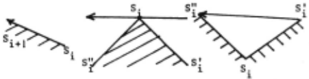
These definitions yield the trivial proposi tion : a finger with a lenght less than L can only touch the silhouette at points belonging to one primitive.
We now introduce a parametrisation of the primitives which corresponds to the intuitive idea that positioning the finger D on to a primitive P requires three conditions : D must be near P, must not intersect with the workpiece and must be cor rectly oriented.
Four parameters are sufficient to define each primitive. Thus the convex and concave primitives are characterised by their associated oriented segment. So in every case, the parametrisation of a primitive is equivalent to the parametrisation of an oriented segment.
Let {R} denote a reference frame whose ori'gin is 0. We call the parameters of an oriented segment V the 4-tuple (1,a,d,h) where 1 is the euclidian norm of V, a its orientation d and h the coordi nates of its middle M expressed in the frame {R} by the rotation (O,a).
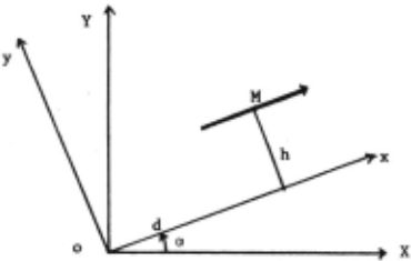
The parameters of the oriented segment associ ated with the primitive P are called the parame ters of P and we write P · (1,a,d,h).
Similarly, the parameters of · the finger D are those of its edge oriented in such a way that it forms with the direction of tightening a direct frame. It is noted D · (L,e,o,().
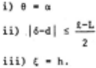
The stable positioning of a finger /J on to a prim1t1ve 1' involves three conditions : the orien·· tation of U toassurc the stability, the lateral po6itioning to assure that D will reach P, and the positioning normal to the orientation of the primi tive of D to assure that D does not intersect with the workpiece. It is proved in [8] that, for the three types of primitive~, the first condition is a fonction of e exclusively, the second one of e and 6, the third one of e,o and (. This property will yield an analytical solution in the case of several coupled fingers.
We give, as an example, the trivial case of a straight primitive for which the conditions are (without friction)
The other cases are given in the appendix and yield the classification of the stable grasps : the sets Mi of the stable positions of D on to the different primitives of the silhouette constitute a partition of the set M of the stable positions of D on to the silhouette i.e. u M. · M and i l M. n M. -0 for every i,j (i"j). l J
2. Stable positioning of a ~ras~er alon~ the silhouette
The problem is, now, the positioning of the different fingers of the grasper along the silhou ette. We restrict our study to the case of a gras per with two identical fingers (see Figure 2). The generalisation to other types of graspers is straightforward [8] .
Let Di · (L,ei,oi,(i) be the fingers of the grasper. The constraints in the case of a gras per with two fingers are : e 2 -e 1 zn, o 1 +o 2 ·o, 1;1+(2 < o.
A position of the grasper will be said stable if the fingers are in stable position in the sense of §I and if the distancebetweeo them passes throu gh a local minimum different from 0. This defini tion implies that a grasp associates two primitives, and that some associations of primitives cannot yield a stable grasp. We only have to consider the following cases : the "trapezoid" (S,S), the "triangle" (S,V), the "butterfly" (C,C), the "tunnel" (S,C)
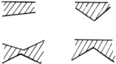
Finding a grasp for the grasper is equivalent to finding the conditions under which two primitives forming one of the above configurations, make a grasp. These conditions are obtained by writing the conditions of the stable positioning of each finger and by reducing the number of variables owing to the constraints of the grasp. It is shown in [8] that for each configuration the solution is simple and analytic. A few tests on the parameters of the primitives allow to know if two primitives constit ute a grasp, and, if so, the possible positions for the grasper. As an example, we give the trivial case of the trapezoid for which the conditions are :
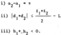
The possible positions of the grasper are t 1 -L defined by: e 1 -a 1 , l6 1 -d 1 1 s ---, F; 1 ·h 1 and 2 the constraints of the grasper.
The other cases, given in the appendix, are very similar.
Two remarks must be made. Firstly, because of the simplicity of the solution, the method is very quick. Secondly, we get without any more calcula tion the tolerancies 68 and 66 on e and 6. They are, for a given type T of configuration, a good measure of the stability and so of the quality of the grasp, useful to order the grasps. The criteria may be of the form ).T+u8+v66.
Finally the complexity of the algorithm which is, a priori O(n2) may be reduced to O(n log n) if the primitives are sorted according to their orientations [8].
IV. EXPERIMENTAL STUDY
The bin to be observed is a cubical one, 75 em wide. For industrial reasons the whole sensor (camera, laser, and its optics) must be 4 m from the ground. To observe the whole bin whose edges are not transparent the cameras must not be more than 37.5 em from the bin's axis. This is a very disadbantageous condition for the "z" precision b~cause the stereoscopic angle is only 12". The experimental sensor has 1024 photodiodes arrays and thus we obtain a precision of 0.7 mm in z and one of 0.3 mm in x andy. This is superfulous in th~ following example, where the maximum length of the workpieces are about 20 em : in this case, simulation shows that a precision of 3 mm is sufficient, and hence, the length of the photodio ues arrays might be reduced.
A 100 mwatt laser is used, with a diameter equal to 1.3 mm having a divergence of 0.6 mrad. Th~ optics composed of four lenses keep the diameter constant and equal to 0.7 mm on the entire bin.
Figure 2 shows a photograph of the bin. One notices that intensity data does not permit extrac tion of outlines of workpieces. In Figure 3(a), the dotted lines represent the laser beam's course from an origin to a breakpoint, and the along the outline of a workpiece on the top of the bin. The continuous line is the piecewise linear approxima tion of the silhouette. Figure 3(b), (c), (d) shows three possible grasps among the best ones. The criteria used to order the grasps is the criteria defined in section III2 added with some heuristics that prevent the workpiece to fall down or stay in the bin, based on the relative position of the grasp and· the ~stimated moments of inertia of the workpiece.
V CONCLUSION
A new 3-D sensor and one of its possible applications, the bin picking, has b~en presented.
In that application the sensor is used as a fast edge detector, allowing to isolate a workpiece or part of a workpiece on the top of the bin. Then a general algorithm defines the possible grasps along the silhouette (a representation of the object to be handled is not required); it may be used to solve many other problems of automatic prehension, when the object is unknown or when a particular orientation of the object is not needed.
@inproceedings{ijcai1981p153,
  title     = {A New Approach to the Problem of Acquiring Randomly Oriented Workpieces Out of a Bin},
  author    = {Boissonnat, Jean-Daniel and Germain, F.},
  booktitle = {Proceedings of the Seventh International Joint Conference on
               Artificial Intelligence, {IJCAI-81}},
  publisher = {International Joint Conferences on Artificial Intelligence},
  editor    = {Patrick J. Hayes},
  pages     = {796--801},
  year      = {1981},
  month     = {8},
  note      = {Robotics},
  url       = {https://ijcai.org/proceedings/1981/153},
}
TY - CPAPER TI - A New Approach to the Problem of Acquiring Randomly Oriented Workpieces Out of a Bin AU - Boissonnat, Jean-Daniel AU - Germain, F. T2 - Proceedings of the Seventh International Joint Conference on Artificial Intelligence, IJCAI-81 PB - International Joint Conferences on Artificial Intelligence PY - 1981 SP - 796 EP - 801 UR - https://ijcai.org/proceedings/1981/153 ER -Copied
Machine-readable versions of this paper, for tools and AI agents:
 Welcome
 Future Conferences
 AI Journal Division
 IJCAI Proceedings
 About IJCAI
 IJCAI Awards