
A Locomotion Control System for Mobile Robots
Proceedings of the Seventh International Joint Conference on Artificial Intelligence. Robotics. Pages 779-783.
© 1981 International Joint Conferences on Artificial Intelligence
Abstract
This paper discusses how to control and describe the smooth movement of a mobile robot which has two independent driving wheels (IDWs) that perform bo th steering and moving functions. Robots which have an IDW leg system can move to any point by using any combinations of two basic operations: revolving and going straight. It is easy to describe movement with two basic operations only, but this may not be sufficient to guarantee smooth motion. For instance, when the robot is moving, a slight modification to its track direction is impossible without stopping it. Smooth motions are also needed for minimizing the time required to complete the movement. Theoretically, an IDW leg system can draw a circular track with radius 0 - m if one controls the ratio of the two wheel speeds. This principle underlies much of the design of this control system. The control system described in this paper uses three basic motion commands, supplemented by other commands that support these. A language has been designed for describing leg control algorithms. Examples of the usage of these commands and the language are shown here.
- Thompson, A. M. "The Navigation System of the JPL Robot" Proc. of 5th IJCAI, 1977, 749-757. IJCAI
- Nilsson, N. Application Techniques" 509-520.
- J. "A Mobile Automation: An of Artificial Intelligence Proc. of lst IJCAI, 1969,
- Coles, L. S . et.al. "Decision Analysis for an Experimental Robot with an Unreliable Sensors" Proc. of 4th IJCAI, 1975, 749-757.
- Giralt, G. et.al. "A Multi-Level Planning and Navigation System for a Mobile Robot" Proc. of 6th IJCAI, 1979, 335-337 . --
- Miller, J . A. "The Autonomous Guidance and Control of a Roving Robot" Proc. of 5th IJCAI, 1977, 759-760. --
- Kanayama, Y. et.al. "A Mobile Robot with Sonic Sensors and its Understanding of a Simple World" Technical Report of Institute of Information Sciences and Electronics, University of Tsukuba:-fSE-TR-Bl-22, Feb., 1981.
References were extracted automatically from the PDF and may contain errors.
Full text extracted automatically from the PDF; figures, tables and equations may differ. The PDF is the version of record.
A LOCOMOTION CONTROL SYSTEM FOR MOBILE ROBOTS
* ** ** Jun'ichi Iijima, Yutaka Kanayama, and Shin'ichi Yuta
- The University of Electro-Communications, Chofu, Tokyo 182 Japan
- ** University of Tsukuba, Sakura, Ibaraki 305 Japan
ABSTRACT
This paper discusses how to control and describe the smooth movement of a mobile robot which has two independent driving wheels (IDWs) that perform both steering and moving functions. Robots which have an IDW leg system can move to any point by using any combinations of two basic operations: revolving and going straight.
It is easy to describe movement with two basic operations only, but this may not be sufficient to guarantee smooth motion. For instance, when the robot is moving, a slight modification to its track direction is impossible without stopping it. Smooth motions are also needed for minimizing the time required to complete the movement.
Theoretically, an IDW leg system can draw a circular track with radius 0 - m if one controls the ratio of the two wheel speeds. This principle underlies much of the design of this control system.
The control system described in this paper uses three basic motion commands, supplemented by other commands that support these. A language has been designed for describing leg control algorithms. Examples of the usage of these commands and the language are shown here.
0. INTRODUCTION
Several mobile robots have been developed for AI research. Their mobile mechanisms have two
essential functions:
- to ensure smooth movement, and
- to know the current position and direction in the world.
Steering methods perform the first function by one of the following schemes:
- steering and moving by driving wheels and steering wheels.
- steering and moving by driving wheels that have a steering function [1).
- steering and moving by two independent driving wheels (IDWs) that make the robot move in any arbitrarily selected direction [2)[ 3)[4) .
This research was supported by grants in aid for scientific research from the Ministry of Education of the Japanese Government.
We call the last one an IDW method. Robots with IDW leg systems are widely used because, without any separate steering mechanism, they can move to any point by a combination of revolving and going straight.
It is easy to achieve movement using only these two basic operations, but this does not guarantee smooth motion. For instance, when the robot is moving, a slight modification to its track direction requires stopping the forward motion. Smooth motions are useful to minimize the time required to complete the movement .
Theoretically, an IDW leg system can draw a circular track with any arbitrary radius 0 - m, given control of the ratio of the two wheel speeds. Furthermore, the radius of the track can be changed smoothly by increasing or decreasing the wheel speeds with constant acceleration. In order to control these capabilities, the command system described in this paper has been designed and has
been installed on a mobile robot, Yamabico 3.1 [6).
Yamabico 3.1 has two microcomputer systems for the brain and the legs, and has a communication channel between the two. When the robot is to p,o to a destination, path finding and command sequence planning are executed by the brain, while the leg subsystem performs low level motor control functions. A similar functional distribution is used on the robot reported in reference [ 5).
Important information about the motion of the robot includes its position, direction, velocity and travelling distance, and this is called leg status. The brain issues commands to the leg subsystem to reference and update the leg status and to control movement, using the interface channel between these two subsystems. The leg subsystem confirms to the brain that each command has been executed. Variables of the leg status are
listed in Table 1.
This information can be divided into static and dynamic information. Static information includes:
- The position of the robot
- A point C in the robot is defined as the center of the robot. A direction D is defined on
| variable | value |
|---|---|
| XX yy DD | x coordinate y coordinate } of the position direction of the robot |
| ss | travelling distance of the robot's center ( odometer ) |
| xxo YYO DDO | offset value of XX } offset value of yy in a command offset value of DD |
| sso | offset value of ss in a command |
| VR VL | present speed of the right driving wheel present speed of the left driving wheel |
| STR CNS | {true, if the robot is moving straight, false, otherwise. {true, if the robot is moving at a constant speed, false, otherwise. |
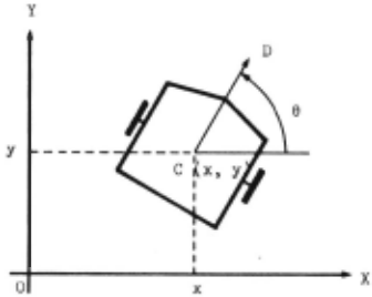
the robot, and called the reference direction. '!'he robot lives in a world of two-dimensional standard coordinates. The position of the robot, P, is expressed in a 3-tuple (x, y, e), where x andy are the standard coordinates of its location and e is the angle between D and the X axis. The standard coordinates are given by an initialization process after the robot "awakens". (See Fig. 1)
In the leg status, the position (x, y, e) is represented by XX, YY and DD in this order.
(2) The travelling distance
The leg status has an odometer, SS, which records the .travelling distance of the robot from the initial location to its present location.
(3) Offset values in a command
XXO, YYO, DDO and SSO give, respectively, the difference between the current values and the values at the beginning of the most recent command affecting XX, YY, DD and SS. If the position is (x 0 , Yo· e 0 ) and the travelling distance is s 0 at the beginn1ng of a command, then XXO, YYO, DDO and SSO are determined as:
XXO XX - xo
yy y YYO
DDO - eo DD O
sso ss - so
where XX, YY, DD and SS represent the current values of the position and the travelling distance.
Dynamic information includes:
(4) The velocity of the robot
The velocity of the robot is expressed by the time derivatives of position: dx, ~and de. In dt dt dt
a robot controlled by the IDW method one of these derivatives can be expressed by the ~ther two. Therefore a pair of driving wheel speeds can express the velocity of the robot.
We adopted this representation. VR and V 1, ure the current speeds of the right and left wheels, respectively, and take positive values when the robot is mavin~ forward.
(5) Flags
There are two flap,s, STR and CNS in the le~ status. The fla~ STR is true if the robot is moving straight, otherwise false. The flag CNS is true if the r obot is moving at a constant speed, and false otherwise.
2. THE COMMAND SYSTEM
The brain sends orders for robot movement to the leg subsystem through a command sequence. There are two kinds of commands:
- motion commands
- control commands.
Motion commands are associated with the movement of the robot; control commands are related to leg status and to the control of the execution of a command sequence. Each command in the sequence is interpreted and executed by the leg subsystem. When a command has been executed, the leg subsystem returns replies to the brain. The information in the replies includes:
- the termination of the command (normal or abnormal termination), or
- the value of the variable in the leg status, or
- signallin~ that an interval of diGtance or angular movement has been travelled.
Syntax and semantics of the commands are described in 2.1 and 2.2, respectively, where the syntax is a reference language for describing leg controlling algorithms. Examples of the command sequences are shown in 2 .3.
2.1 Syntax for the Command
The context-free syntax of the skeleton of the command system is described using a variant of the Backus-Naur Form, where braces { } denote zero or more repetitions and square brackets [ ) enclose optional items.
- Command o. equences <command sequence> <command > {; <crnrnand> }
- (2 ) Commands <command > : : =<motion command> I <control command >
- Motion commands
<motion command> : :=<operation>
<speed specifi cation>
[until <terminating condition>)
<radius> I spin
<operation> : := gostraight I turn with
<speed speci fication> : : = in <speed>
<terminating condition> : :=<variable 1> =
= <speed> I STR
<value> I speed
CNS
- <control command> <get command> <update command> <set command> <reset command> <queue command> ··=<get command> I <update command> <set command> I <reset command> I <queue command> ··=get (<variable 1>) ··=update ( <variable 2>, <value>) ··=set (<interval>, <value>) reset (<interval>) · ·=terminate I cancel
- Control commands
- Miscellaneous items
DDO I sso I VL I VR
<variable 1> .. <variable 2> I XXO I YYO I
<variable 2> : := XX I YY I DD I SS
<interval > : := DDI I SSI
Detailed definitions of <speed>, <radius> and <··al ue> are not given here.
Examples
- Motion commands gostraight in v until SSO = ~ turn with r in v until DDO = d spin in v
- Control commands
- p:et (SG) r:ct (SSI, 10)
update (XX, O) reset (DD)
- terminate cancel
2.2 Semantics f or the Command
Each command in the sequence from the brain is accepted by the leg subsystem in its order in the sequence. Each motion command in a command sequence i s s t ored in a first in first out (FIFO) s t orage and each control command is immediately executed by-pass ing the FIFO stor e . After the first command in the storage is executed and terminated, it is discarded and the next command is taken to be processed . If there exist no commands in the FIFO storage, the command 'gos t r a i ght in 0' is executed; thi s command never termi nates.
Operations of the motion commands are described in 2. 2 .1. Section 2.2.2 describes operations of the control commands.
2. 2.1 Motion Commands
The motion command causes the robot to do the designated movement. and executed when the first position of the terminating condition command is terminated the first position of The command is interpreted command is placed in the FIFO storage. When the is satisfied, the current and the next command occupies the FIFO storage.
There is a transient state between the execution of two commands. In a transient state, each driving wheel moves with uniform acceleration, as di scussed later.
The motion command consists of three specifications: an operation, a speed specification, and a terminating condition; the last of these can be omitted. There are three operations: going straight, moving along a circle of radius r, and revolving. The speed specification determines the speed of the robot's center when it is going straight or moving on a circular path, and the speed of the right wheel when the robot is revolving.
The operation and the speed specification of the commaud jointly determine two other values: the steady-state right and left wheel speeds. These are called the right target speed (rts) and the left target speed (lts), respectively.
Details of the motion commands are :
(1) Gostraight command
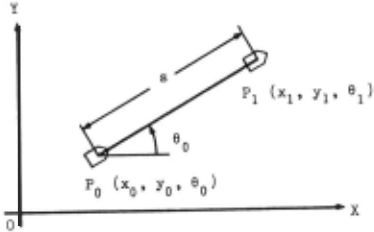
This command causes the robot to move straight at the specified speed v until the terminating condition is satisfied. The speed vis positive if the robot is to move forward and negative if backward. The target speed of each wheel is v. The robot is placed in the position Po (x 0 , Yo· e 0 ) at the beginning of the command, and travels a distances by executing the command (See Fig. 2). The leg status after the execution of the command changes as follows:
where s 0 is the value of SS at the beginning of the command execution.
{2) Turn command
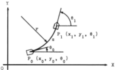
This command causes the robot to move along a circule of radius r, specified by the <radius>, and it is terminated when the terminating condition is satisfied (See Fig. 3), If the robot is directed to move at a speed v then the target speeds rts and lts are r + dt v and r - dt v , respectively, r r
where dt is half of the tread distance, and r is the radius of the circle which is followed by the robot. If r is positive the~the robot steers toward the left, otherwise toward the right. The speed v is positive if the robot moves forward, negative if it moves backward.
0
Fig. 3 Movement by a turn command
(3) Spin command
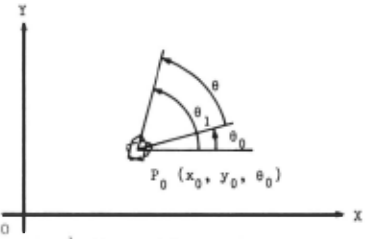
This command causes the robot to pivot on its center until the terminating condition is satisfied. If the speed v, given by the speed specification, is positive then the robot revolves counter-clockwise, and if negative then it revolves clockwise. The target speed rts is v and lts is -rts, so that the wheels move in opposite directions. (See Fig. 4) Each variable of the lep status changes as follows:
(4) Moving in the transient state When a command is terminated and the next one is executed, there is a change of target speeds.
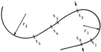
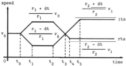
From that time, driving wheels approach the new target speed at a uniform acceleration. If the center velocity v is kept constant, the path is always a trochoid whose curvature changes linearly with respect to the travelling distance.
Suppose, for example, the following command sequence is executed:
where CO, Cl and C2 are tetminatir.e conditions.
The path for this command sequence is shown in Fig. 5. Fig. 6 shows the change of the speed rate for the sequence.
The robot has the following target speeds at the end of the execution of the first command:
At that time, the real speeds of the wheels are equal to the target speeds.
The second command is started at the time t 0 (an arrow t in Fig. 5 denotes the beginning of a command). New target speeds are given to draw a circle of radius r 1 at speed v 0 :
Each driving wheel approaches its new target speed at uniform acceleration. In this case, the transient path is a trochoid because the speed of the robot's center is not changed.
The speeds of both wheels reach the target speeds at the time t ; the leg is then in stationary state and 1 CNS is true. The condition Cl is satisfied at the time t 2 , the second command is terminated and the last one is started. The next target speeds are given as:
Then the left wheel speed is reduced and the right wheel speed is increased.
(5) Terminating conditions
While the command is being executed, the leg subsystem examines the terminating condition. If the condition is satisfied then the command is terminated. If the condition has the format v = k, where v is a variable in the leg status specified by the <variable 1>, then the value of v, value(v), is compared with k. The condition is satisfied if value(v) is greater than or equal to k when value(v) is increasing, or if value(v) is less than or equal to k when the value(v) is decreasing.
The condition 'speed = vt' is satisfied if the speed of the robot's center is equal to the specified value in the case of gostraight and turn commands, or if the speed of the right wheel is equal to the specified value in the case of. the spin cominand.
The condition STR is satisfied if the robot goes straight, which occurs when the two driving wheels have equal speed. The condition CNS is satisfied if both driving wheels have zero acceleration.
Some terminating conditions may remain unsatisfied indefinitly. The terminating condition can be omitted. If the command has no condition then it is not terminated.
2.2.2 Control Commands
The acceptance and the execution of control commands do not modify the state of the FIFO storage and the execution state of the motion command, except for terminate and cancel commands. The operations of the control commands are as follows:
(1) Get command
The value of the variable, specified by <variable 1>, of the leg status is returned as a reply. The returned value is the value the lef. status has at that moment.
For example, 'get (SS)' returns the value of the odometer.
(2) Update command
The command writes the value of the variable of the leg status specified by <variable 2>.
(3) Set and .reset commands
The leg subsystem always monitors the travelling distance, the direction of the robot, and the other variables in the leg status. It has a mechanism which can generate signals for the brain at a given distance or direction interval. For example, signals can be generated each time the robot moves 10 em. This feature is useful, for example, when the robot measures distances to the left side wall at equal intervals. The intervals in distance and direction are recorded in SSI and DDI, respectively. DDI and SSI are not included in the leg $tatus because they need not be read by the brain.
When a set command is accepted, the leg subsystem begins to generate signals each time the robot moves the specified distance or direction.
The reset command terminates this generation of signals.
2.3 Examples of Command Sequences
These examples show the usage of the command sequence.
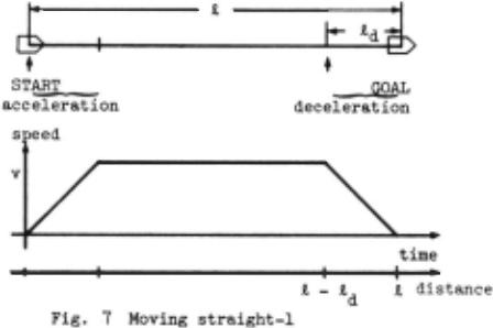
(1) Moving straight-1
The robot moves a distance t. It starts from a stopped state, and stops at the destination. gostraight in v until 1 - 1 d; gostraight in 0 until speed = 0 where 1 requirell speed v, is the braking distance or distance to stop the robot when it is moving at a and it is known.
The path and the speed rate change are shown in Fig. 1.
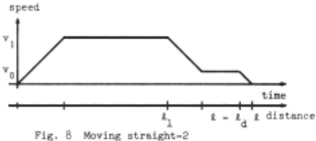
(2) Moving straight-2
This is similar to (1), except that the robot slows to its. minimum possible speed v before it reaches the destination, then stops . 0 This sequence is better than the sequence described in (1) for travelling an accurate distance. The speed rate is altered as shown in Fig. 8.
( 3 ) Changing the direction
The robot revolves through the angle 6 (See Fig. 9)
whe re 6d i s the-angle required to stop the robot when it is revolving at speed v 2 .
Using the sequences described above, the robot can move anywhere. This does not, however, assume smooth motion .
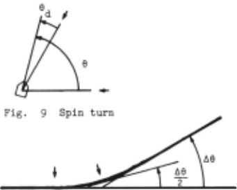
- Modification of the walking direction While the robot is moving, it modifies its walking direction by a small angle 66 (See
turn with r in v until DDO = 66/2; gostraight in v until some terminating
- Fig. 10). condition
where the value of r can be any arbitrary small value.
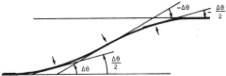
The robot changes from one lane to another
turn with r in v until DDO = 66/2; gostraight i~v until STR; turn with -r-in v until DDO = -66/2; gostraight in~ until STR
where r can take any s;all value, and 66 is any
- ( 5) Char,ging lane (See Fig . . 11). small angle.
3. CONCLUDING REMARKS
We have presented a command system for controlling movement of a mobile robot which is steered and moved by controllinp, two driving wheels independently . Smooth motions can be achieved through using this command system, and the terminating condition is also useful.
We have been implementing the lcf, status and the command system on a mobile robot, Yamabico 3.1. The implementation and results will be reported in subsequent papers.
ACKNOWLEDGEMENTS
The authors thank Professors J. W. Higgins of University of Tsukuba and T. Furugori of the University of Electro-Communications for their useful suggestions and critical reading of the manuscript.
@inproceedings{ijcai1981p150,
  title     = {A Locomotion Control System for Mobile Robots},
  author    = {Iijima, Jun'ichi and Kanayama, Yutaka and Yuta, Shin'ichi},
  booktitle = {Proceedings of the Seventh International Joint Conference on
               Artificial Intelligence, {IJCAI-81}},
  publisher = {International Joint Conferences on Artificial Intelligence},
  editor    = {Patrick J. Hayes},
  pages     = {779--783},
  year      = {1981},
  month     = {8},
  note      = {Robotics},
  url       = {https://ijcai.org/proceedings/1981/150},
}
TY - CPAPER TI - A Locomotion Control System for Mobile Robots AU - Iijima, Jun'ichi AU - Kanayama, Yutaka AU - Yuta, Shin'ichi T2 - Proceedings of the Seventh International Joint Conference on Artificial Intelligence, IJCAI-81 PB - International Joint Conferences on Artificial Intelligence PY - 1981 SP - 779 EP - 783 UR - https://ijcai.org/proceedings/1981/150 ER -Copied
Machine-readable versions of this paper, for tools and AI agents:
 Welcome
 Future Conferences
 AI Journal Division
 IJCAI Proceedings
 About IJCAI
 IJCAI Awards