
Forming Models Of Plane-And-Cylinder Faceled Bodies From Light Stripes
Proceedings of the Fourth International Joint Conference on Artificial Intelligence. Visual Information Processing. Pages 664-667.
© 1975 International Joint Conferences on Artificial Intelligence
Abstract
A system is described which uses light stripe input to construct 3-D body models useful for automatic assembly. Special hardware can extract a stripe from a TV picture in about .02 second. Clusters of stripes from single surfaces in the body, and hence the equations of the surfaces themselves, are found by a program which forms hypotheses based on clues in the data and then tries to establish them. The resulting surface equations and the stripe evidence for them are used to produce the body model, which is a union of convex subsets of three-space formed as intersections of {possibly complemented) half-spaces and solid cylinders.
- Shirai, Y. and Suwa, M. Recognition of poly- hedrons with a range finder. Proceedings of the Second International Joint Con- ference on Artifi cia 1 Inte 11 i gence, London, 1971 IJCAI
- Agin, G. J. Representation and description of curved objects. Report AIM-173, Stanford Artificial Intelligence Laboratory, Stanford, California, 1972.
- Braid, I. C. Designing with volumes . Ph.D . Thesis, Computer Aided Design Group, University of Cambridge, Cambridge, England, 1973.
- Brown, C. M. Low-level striping routines. DAI-WP-3, Department of Artificial In- telligence, University of Edinburgh, Edinburgh, 1974.
- Crawford, G. F. The stripe finder hardware . DAI Research Memo, Department of Arti- ficial Intelligence, University of Edinburgh, Edinburgh, 1974.
- Duda, R. 0., and Hart, P. E. Pattern Recognition and Scene Analysis, Wiley and Sons, New York, 1973.
- Brown C. M. The striper calibration system . DAI-WP-4, Department of Artificial Intel- ligence, University of Edinburgh, Edinburgh, 1974.
- Barrow, H. G., Ambler, A. P., and Burstall, R. M. Some techniques for recognizing structures in pictures. In Frontiers of Pattern Recognition (ed . S. Watanabe), Academic Press, New York, 1972.
- Freuder, E. C. Active knowledge. Vision Flash 53, Artificial Intelligence Laboratory, Massachusetts Institute of Technology, Cambridge, .Massachusetts, 1973 .
- Brown, C. M. The HYPer system. DAI Working Paper, Department of Artificial Intel- ligence, University of Edinburgh, Edinburgh, 1974.
References were extracted automatically from the PDF and may contain errors.
Full text extracted automatically from the PDF; figures, tables and equations may differ. The PDF is the version of record.
Introduction
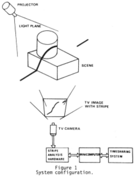
This paper describes a system for der~ving three-dimensional (3-0) body models from optical input data (Figure 1). As in the work of Shirai [1] and Agin [2] , a plane of light is moved across the object under investigation. By viewing the result ing light stripes from another angle, points on them may be located in space using triangulation. Our work differs from Shirai's in that it deals with bodies having cylindrical as well as planar faces, and from both other projects in its concern with body models useful in solving problems of automatic assembly such as "how can this face be placed against that one", or "will these two objects clash if I do that to them".
We use a representation of 3-D bodies derived from that used by Lang and Braid [3]. Body models are built up from two kinds of primitives: the half-space H, defined as the set of points {(x,y,z) 1 x ~ 0}, and t~e infinite cylin~er 2 £r. 2 defined as the set of po1nts r(x,y,z) I x +y ~ r }. Bodies are represented as boolean combinations of sets resulting from transformations of the (perhaps complemented) primitives by members of the affine group of all rotations and translations of three space. Thus a rod would be represented as an inter section of a transformed cylinder and two trans formed half-spaces.
The system to build a body model from an object has been developed in three parts:
- The stripe finder, a hardware device which rapidly extracts a stripe from a TV frame .
- The surface finder, a software module which produces the surfaces of the object from the output of the stripe finder.
- The model builder, a software module which produces a body model from the output of the surface finder.
At present the two software modules run in strict sequence, but it is intended to make them interact, so that if, for instance, the model builder discovers that a surface has been missed, it can request a search for it. The process of changing over computing hardware and of continued development of the surface finder has delayed final integration of the system. The model shown in Figure 6 was produced by storing surface finder output on disk for use by the model builder .
The stripe finder
If an ordinary TV camera is used to view a stripe which is nearly vertical as seen by the camera, then the stripe intersects each line of the TV scan only once, producing a single brief bright ness pulse on the video wave form for each line . Since each TV line is scanned at a constant speed, the time taken for the scan to move from the start (left side) of a given line to this video pulse is proportional to the distance of the stripe from the edge of the picture for that line. This fact is used by the stripe hardware.
- A program [4] to use the striper specifies : 1. A brightness threshold, so that unwanted low level light {possibly scattered or reflected stripe light) can be ignored by the stripe finder.
- A TV scan line to be tested.
- A left-hand margin for the TV picture, within which the stripe detector is inhibited, so that the whole picture need not be dark.
The stripe finder returns a result which is the number of ticks elapsed on a fast clock between the start of the scan on the chosen line and the time the stripe is encountered. Minicomputer software is fast enough to permit stripe information from successive TV lines to be acquired and stored, so data from an entire strip may be collected in one TV frame time. A detailed account of the stripe finder is given in [5].
The surface finder
General strategy
- A "scan" consists of a collection of stripes. A decision is made as to the spacing of stripes and direction of scans needed to give good evidence for the surfaces of the object under in vestigation; the scans are produced and put in a
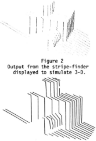
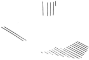
- 1 i st. 2. The individual stripes comprising the scan {Figure 2) are segmented into linear segments {Fig ure 3), all of which are marked "unexplained".
- The segment endpoints are located in threespace.
- A scan containing unexplained segments is chosen from the list of scans produced in step 1. If no such scan exists, all surfaces have been found; otherwise, let S be the set of unexplained segments in this scan.
- S is examined for curved sections of stripe wrongly described as sets of linear segments; such sections, if found, form a segment class, "curved" segments. The rest of S {consisting of linear segments) is divided into "horizontal", "vertical", and "general" segment classes.
- Within the above classes, clusters are formed. The are named according to the type of surface with which they will be fitted; there are thus "plane clusters" and "cylinder clusters". Some clusters of linear segments may in fact arise from cylinders; they are named "ambiguous clusters" {Figure 4). Not all segments in Sneed be put in clusters.
- Surfaces are fitted to the clusters. Both planes and cylinders are fitted to ambiguous clus ters and the type of surface providing the best fit is chosen.
- Each surface found in step 7 is considered as a prediction that some unexplained segments lie in it. The entire list of scans is searched for such segments, the set of which {presumably con taining most of the segments in the original clus ter for this surface) becomes the "evidence" for the surface. The surface is refitted to the evidence, and the evidence segments are marked "explained". The strategy is re-entered at step 4.
Specific techniques
Here some aspects of the general strategy are enlarged upon; the paragraph numbers correspond to those of the general strategy.
- The decision as to which scans to produce will ultimat.P.ly he left to the system, including the model-builder. The decision arises in a natural way when the upper levels of interpretation wish more information about an inadequately sensed or a hypothesized surface. There is no need to make all the scans at once; segments can be accepted into known surfaces as the scans are produced.
- The 2-0 stripes (in TV co-ordinates) are segmented by a recursive algorithm similar to one described in Ouda and Hart [6]; each straight line segment is broken into two new segments at the point of its maximum deviation from the stripe if the deviation is above a threshold. A segment between stripeend-points starts the process.
- The 2-0 to 3-0 conversion process uses a matrix associated with each scan [7]. The 3-0 co ordinates are fixed with respect to the body.
- This step is clear.
- The segmentation algorithm produces a set of linear segments from a curved section of stripe. Curved segments are recovered from linear ones by rejoining the linear ones if the change of angle between them is not sudden . Linear segment classes are decided on using the direction of segments considered as 3-0 vectors .
- Linear segments are clustered by accepting them one at a time into clusters on the basis of direction, overlap, distance, and adjacency criter ia. Curved segments are at present clustered only on the basis of overlap and adjacency. Cylinders w~ose ~xes are nearly_parallel to the light plane g1ve r1se to nearly 11near segments of str1pe and
hence to linear segments; clusters which might have arisen from such cylinders are detectable through a number of cues, and are called "ambiguous clusters". There is no need at this stage to accept every seg ment into a cluster; when in doubt, it is best to leave a segment out, since it will likely be ac cepted into a surface at step 8.
7. Planes are fitted by an eigenvector method [6] which computes the principle axes of a set of points in 3-space, and thus can provide a least squared error fit (error being perpendicular dis tance and thus independent of choice of axis) for both planes and lines . Cylinders are fitted by an iterative minimisation algorithm, which requires an efficient cylinder representation and a good initial guess for the cylinder parameters.
A cylinder is described by an axis line and a radius r; the axis line may be specified by its direction and a point on it (i .e. a unit 3-D dir ection vector ~and a 3-D point vector x). One component of Cis redundant s i nee I~ I ~1; one com ponent of ! may be forced to a constant zero by forcing! to lie on one of the planes X=O, Y=O, Z=O; the plane chosen here should be the one minimising lxl. The parameter vector given to the minimisation aTgorithm consists of r, two components of ~ and two components of x. Which component of x has oeen forced to zero- is remembered as an additional piece of information in the cylinder representation.
The minimisation algorithm needs a good estimate for the cylinder because of the paucity of cylinder data produced in a single scan. To get the estimat& £is estimated first and then the points to be fit ted are projected onto a plane perpendicular to f... A circle is fitted to the projected points, giving estimates for x and r.
~ is estimated for cylinder clusters by using the fact that the angle of intersection of the light plane with a cylinder's axis stays constant throughout any scan. Thus the intersection of the light plane with the cylinder always gives the same ellipse shifted in space parallel to the axis, i.e. parallel to c If corresponding points on these shifted ellTpses can be identified, the vec tor between the ooints will be parallel to the axis, and hence will specify f..· In fact, instead of complete ellipses, the curved segments of stripe which form a cylinder cluster must be used to find the shift.
The i-determination algorithm uses the fact that consecutive ellipse sections, i.e. segments from successive stripes in a cylinder cluster, will have approximately equal slopes (in 2-D TV co ordinates) at corresponding points. The slopes along two such segments are computed by taking first differences of their horizontal co-ordinate; the two resulting series of slopes are allowed to "slide past" one another, taking on all relative displacements in some interval. Each displacement puts a set of slopes from one series opposite a set from the other, and for each displacement the goodness of the match between the opposite members of the two sets is computed. The displacement giving the best match is taken to define corres ponding points of the segments . Once a f.. is found from corresponding points in the first two segments considered, it can act as a prediction which allows a much reduced interval of displacements to be considered in succeeding ~-determinations using pairs of segments from successive scans in the cluster . The final estimate of ~ is the unit vector in the direction of the sum of ~·s deter mined by the segment pairs. Since curved segments when projected along~ lie around the circle to be fitted, a simple least-squared error criterion is used to define the circle and thus estimate x and r.
For ambiguous clusters of linear segments, ~ is estimated to be in the direction of one of the segments, all of which are approximately per pendicular to the circle to be fitted . Three of the segments are projected onto a plane; each set of projected points from a segment has a mean 2-D position, and the circle is passed through these three mean positions. This method is an attempt to force the circle to pass through the segments, as it should do. Estimates tor the radius and two compoinents of x are thus found; the third COmponent Of X is estimated as the average of the third compoinents of the three segments .
8. This step is clear.
A hypothesis-based system
The strategy is implemented in a system called HYPer, which owes much in form to hierarchical synthesis (see Barrow et al., [ 8 J) and to Freuder's SEER [ 9 l It can only be sketchily described here. While running, the system may be thought of as a network whose nodes are hypotheses and whose arcs represent what Freuder calls the relation of "relevance". A hypothesis is the attribution of a predicate to an argument; its name is always of the form [<predicate> <argument>) . Among other qualities a hypothesis has a status (true, false, or pending) and a value, which may be anything (a list, a program, etc.).
A hypothesis is established or falsified and its consequences ramified by running programs as sociated with its predicate . For every predicate P there are two such programs: (DOKNOW P), a program which takes a hypothesis as argument and which establishes or verifies it, and (KNOW P), a program which takes a just-established hypothesis as argument and suggests actions based on knowing the hypothesis' truth or falsity. These programs are run under a priority-ordered job queueing scheme.
The KNOW and DOKNOW programs usually conta in instructions both for performing general com putations and for building and traversing the hypothesis network . The latter instructions are the HYPer primitives:
"Constructive Get" brackets, which get (or initiate action to get) the value of a hypothesis.
AFFIRM and DENY, which assert a hypothesis' truth or falsity and ramify the consequences.
ASSUME, which constructs an "alternative wor ld" in which a hypothesis is true, and ramifies the consequences.
RETRACT, which abandons the alternative world created by a particular ASSUME command.
FAIL, which RETRACTs the most recently ASSUMEd hypothesis .
VERIFY, which allows a value to be suggested for a hypothesis and the suggestion to be tested .
NUDGE, which suggests that a hypothesis be established if a value possibly needed to establish it has been computed.
A system like this can be built to run (i.e . to generate and traverse the hypothesis network) top-down, bottom-up, middle-out, or all three at once. It acquires necessary information from other levels as it is needed, and wakes up programs when values of interest to them have been computed. The HYPer system is more fully described in [10].
- A fictional example showing the action of the simplest primitives may be of interest; suppose the following hypotheses have values of the follow ing sorts :
[PLANE-EVIDENCE <plane-cluster>], a list of segments.
[CLUSTER-PARAMETER <plane-cluster>], a plane parameter vector.
[AMBIGUOUS<plane-cluster>], a truth value.
[PLANE <number>], a surface record.
If Pl were a particular plane cluster, then running DOKNOW([PLANE-EVIDENCE PlJ) miqht result in this kind of activity: DOKNOW(fPLANE-EVIDENCE Pll) wants to collect evidence for a plane by examining the list of scans for unexplained segments lying in the plane specified by the value of [CLUSTER-PARAMETER PlJ, which it requests through Constructive Get bracket~ If the value is unknown (the hypothesis [CLUSTER-PARAMETER Pl] may not even exist yet), DOKNOW([CLUSTER-PARAMETER 'Pl]) is awakened, re membering the now-relevant hypothesis that is requesting the information; DOKNOW([PLANE-EVIDENCE PlJ) is put to sleep . [CLUSTER-PARAMETER PlJ is AFFIRMed when its value is known, resulting in both KNOW([CLUSTER-PARAMETER PIJ) and (because 1t is relevant) DOKNOW([PLANE-EVIDENCE Pl]) being awakened. KNOW([CLUSTER-PARAMETER PlJ) might decide to NUDGE [AMBIGUOUS PlJ, causing DOKNOW([AMBIGUOUS PIJ) to be awakened . Meanwhile, DOKNOW([PLANE-EVIDENCE Pl]) might have AFFIRMed ([PLANE-EVIDENCE PlJ), which in turn could NUDGE [ PLANE 51 to create a final surface record from the evidence in [PLANE-EVIDENCE PI] and the new best-fitting parameter vector.
The model builder
The surface finder sends the model builder a set of surface records, each containing the mathe matical specification for an (infinite) transformed primitive (~ · or fr) and the evidence for the sur face of that primttive. The model produced from these records is a union of cells, where a cell is
- a (finite) intersection of transformed {possibly complemented) primitives . To produce a body model, space is divided into cells defined by the ob served surfaces, and cells are accepted into the union if there is evidence that they contain matter .
The strategy is to start with a cell SKYCUBE which is guaranteed to enclose all the bodies being examined, and to divide this up using the observed surfaces. Since to divide SKYCUBE com pletely by all the surfaces would produce an inconveniently large number of subcells, the effect of small surfaces is localized; SKYCUBE is divided in the following way:
- Identify the surface of the table and divide SKYCUBE by this surface, and make a list of cells, at this point just containing the cell above the table.
- Choose a surface, working in decreasing order of "seen" area; if no surfaces remain, the process has been completed.
- For each cell in the list, if the evidence for the surface shows that it exists within the cell as a matter/void transition, then divide the cell by the surface and replace it by the two resulting cells.
4. Go to step 2.
Evidence is judged adequate for a surface in a cell if in that cell it consists of at least two segments, and the combined length of evidence segments in the cell exceeds a threshold.
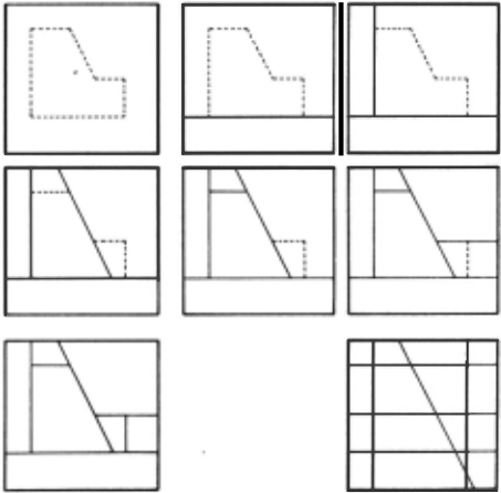
- A 2-D version of this process is shown in Figure 5. After the cell splitting, each surface has been used to divide at least one cell, and all the evidence occurs somewhere in the sur faces of the cells. Tf the surface finder missed no surfaces, each cell obtained by the splitting will represent space either filled with matter or entirely empty.
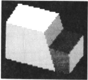
Since the bodies being examined are known to be entirely inside SKYCUBE, any cell with one or more of its surfaces in common with SKYCUBE must be empty . Remaining cells with stripe evidence for a matter/void transition on at least one of their surfaces are classified as being full, others as being empty. Cells entirely surrounded by matter could be classified as being full, but no program currently using body models needs information about such cells. A body model produced from two scans is displayed in Figure 6.
If the surface-finder produces scans with two great a space between stripes, or from too few directions, or from ill-chosen angles, then it may send incomplete information to the model builder. In fact, complete information on a body with deep concavities may be impossible to obtain with the striper. Given incomplete data, the model builder may either
- produce a correct body model, or
- produce an incorrect body model, or
- complain that the date is incomplete.
In future work we must try to minimize occurrences of 2, and provide suggestions to the surface finder so that complaints are intelligently dealt with.
At present, if a cell has at least one surface which is a surface of SKYCUBE and also at least one "visible" surface, or if a cell has a surface which is the complement of some surface for which stripe evidence exists on the cell, then it is assumed that there is a missing surface somewhere inside the cell . It would be possible, by examin ation of the location of the surface evidence to make some inferences about the position of the missing surface, but this i s not done at present.
If all the surfaces of a body are sufficiently large to register with the striper, the main cause of insufficient surface data being gathered is occlusion of surfaces by the body itself. A point on a surface is occluded if either the light plane cannot reach it or the TV camera can not see it. Though a correct body model often arises without all of any surface being seen, it is clearly desirable that the system should have some model of the occlusion process so that it may suggest action if occlusion could have caused a surface to be missed.
Acknowledgements
This work has benefitted from many productive discussions with Dr . H. G. Barrow. The research was supported under Science Research Council Grant Number B/RG 57511.
@inproceedings{ijcai1975p104,
  title     = {Forming Models Of Plane-And-Cylinder Faceled Bodies From Light Stripes},
  author    = {Popplestone, Robin J. and Brown, Christopher M. and Ambler, A. Patricia and Crawford, G.},
  booktitle = {Proceedings of the Fourth International Joint Conference on
               Artificial Intelligence, {IJCAI-75}},
  publisher = {International Joint Conferences on Artificial Intelligence},
  editor    = {Patrick Winston and Carl Hewitt},
  pages     = {664--667},
  year      = {1975},
  note      = {Visual Information Processing},
  url       = {https://ijcai.org/proceedings/1975/104},
}
TY - CPAPER TI - Forming Models Of Plane-And-Cylinder Faceled Bodies From Light Stripes AU - Popplestone, Robin J. AU - Brown, Christopher M. AU - Ambler, A. Patricia AU - Crawford, G. T2 - Proceedings of the Fourth International Joint Conference on Artificial Intelligence, IJCAI-75 PB - International Joint Conferences on Artificial Intelligence PY - 1975 SP - 664 EP - 667 UR - https://ijcai.org/proceedings/1975/104 ER -Copied
Machine-readable versions of this paper, for tools and AI agents:





