
Methods For Analyzing Three Dimensional Scenes
Proceedings of the Fourth International Joint Conference on Artificial Intelligence. Visual Information Processing. Pages 669-672.
© 1975 International Joint Conferences on Artificial Intelligence
Abstract
Several methcxls for analyzing three dimensional scenes are discussed with respect to their advantages and difficulties in getting real three dimensional coordinates. Stereo picture processing and light intersecting methcxls are described along with the result of a new hardware system. On the example of a software system sare special problems with the abstraction of scenes with primitive objects are mentioned. A short look ahecrl to the future closes this paper.
Full text extracted automatically from the PDF; figures, tables and equations may differ. The PDF is the version of record.
1 . Intrcx:luction
When designing a robot system, we have to deal with the problem of hON the robot can get informa tion about its environment. To get full information it seems to be necessary to design a visual input facility. 'Iherefore there is the problem of hON the autanaton can get a three dimensional image of the world from visual information. This paper describes sare systems, designed in the past, and tries to point out their problems and difficulties. Starting from these considerations, a neo.v system is presented with which sare of the well kno.vn difficulties may be overccrne.
2. Stereo pictures
For interpretation of stereo pictures the system needs two pictures of the same scene, taken from different viewing angles (fig. 1). Provided that
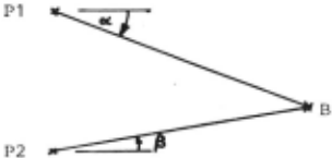
the two camera positions P1 and P2 and the angles Ot and (a are kno.vn, the three dimensional coordi nates of the point B of the scene can be calcula ted. The main problem in stereo picture processing is to define two conjt.qate points in the stereo pair. After the definition of one point in the first picture, the corresporxling point in the se corxl picture must be located. This can only be done if the picture point contains significant in formation, e.g. a corner point. '!his means that we have to deal with two different problems: first, we have to define a significant point in a first picture, and secorxl, we have to reccqnize the cor r esporxling point in the second picture. In order to solve the first problem we have to apply time consuming preprocessing methcx:ls like edge enhance ment, etc. The secon:l problem can be solved by two
P2
dimensional local correlation methcx:ls /1 I. Because of these difficulties, stereo methcxls are not used in fully automatic systems since nON.
3. Light intersecting methcx:ls
In all methcx:ls described below, illumination of the scene is regarded as a part of the recognizing system. Then all visible points of a scene fit with a straight line of light or with an illuminating plane of light. With this information the three di mensional coordinates of all visible points can be calculated from their two dimensional coordinates in the picture. Using this principal several sys tems were designed.
3.1 Laser range fin:ler
The laser range firxling system uses a plane of light with known orientation in space for illumi nation of the scene. The plane of light is genera ted with a laser and a cylin:lrical lens. In such an illuminated scene the camera is able to see only the intersecting line of the light plane and the surface of the scene. The camera takes a cx:::rn plete picture of this image and transmits it to the CXIT'pUter for further processing and extraction of three dimensional coordinates of the intersec ting line. By m::>ving the light source step by step across th whole scene, the process of transmitting pictures and calculating spatial coordinates is re peated. It is evident that there is a large am::>unt of data being transmitted and processed, one pic ture per line, containing very little information. Therefore the system is intolerably timeconsuming, Agin and Binford /5/ need about 5 to 10 minutes per scene.
3.2 Parallel grid illumination
In order to get quick results from the system, one must try to take the complete information of the scene with only one picture, i.e. the scene has to be illuminated with all planes of light at the same time. '!he simplest way to do this is to use an op tical grid, being projected onto the scene. Processing of the picture could be done by tracing the images of the intersecting lines in the pic ture. Canputation of three dimensional coordinates can be done correctly only, if it is possible to identify the images of the lines of light in the picture by their mathematical equations. This prob lem causes sane restrictions to this methcx:l:
- The camera has to be adjusted in such a way that the pictures contain parts of the grourxl surface.
- ShcrlONS, interrupting the image of a line, cause the system to stop tracing the line.
- The camera position must be chosen in such a way that lines, running on the top surface of an object,can be distinguished from those running on the grourrl surface behirxl the obj.
- Scenes with IOClre than one object must not have hidden planes of objects.
In order to be able to identify the light lines by their mathanatical equations it is necessary that the lines start fran the grourrl surface with J<no..m position.
Other difficulties arise in the evaluation of inner and outer parameters of the camera (position,ele vation, rotation and focus) , especially when IOClre than one parameter is variable. I.E. Sobel sugges ted a rrethcrl to solve this problem by imaging a scene with an object of J<no..m size and orientation /2/. If the identity of one line is determined, all points on this line can be cxnp.Ited with their three dirrensional coordinates. But errors may occur if a line is interrupted by shadows or other objects or if there exists a transition fran one line to another, generated by the projection of the carrera (fig. 2).
If all these restrictions are considered and fourrl tolerable to the concrete application, this rrethcrl seerrs to be a quick possibility to analyze three dirrensional scenes. For processing a picture with 256 x 256 samples, containing 25 lines of light, our c<n;Juter COC 33CX:l requires about 30 secorrls to c<n;Jute the c<n;Jlete three dirrensional coordinates of the lines.
3. 3 Grid and point illunination
If the restrictions remarked in 3. 2 are intolerable better results can be achieved by <XJTbining two dif ferent pictures of one scene, taken by the same ca rrera in the same position: one picture contains the image of the grid illuninated scene and the other contains the same scene, illuninated by a point light source. In many cases edges, missing in a grid illuninated scene, are precisly imaged in a corresporrling point illuminated scene and vice versa as shown in fig.3 . The <XJTbination process could be done by three consecutive steps: First we process the grid illuminated scene as far as pos sible and crnpute the three dirrensional scene coor dinates. Then we do sare contour firrling process in the point illuminated image and get a list of contours . Then in a third step we generate a two dirrensional image out of the c<n;JUted three dirren sional coordinates, containing those contours fourrl in the first step. Then we are able to <XJTbine both two dirrensional contour pictures getting a picture containing all contours fran both images.
3. 4 Hardware extraction of three dirrensional coordinates
In all light intersecting methcrls for analyzing three dirrensional scenes described above, one of the three coordinates is c:arputed fran the data of illumination and two coordinates fran the data of the picture. This can be changed so, that two coor dinates are derived from the illumination and only one coordinate fran the carrera. Then we get subsys tems which can be built easily in hardware, being not too expensive.
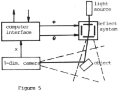
The scene is illuninated by a single beam of light, generated by a locally fixed laser and deflected urrler ccrrputer control by an electrooptical deflec tion system. The scene is scanned systematically and in each position of the laser beam, the two equations describing the straight line of the light beam in space are well l<no.om. Projection of the scene is made by a cylirrlrical lens onto a one dirrensional carrera, designed as a line of photo di odes of CXD-technology. Thus each sensor of the ca rrera represents a plane in space as shown in fig. 4.
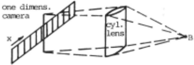
carrera -11' .
Figure 4
Only the intersecting point of this plane and the straight line, forrred by the deflected laser beam, is visible to the system, so three dirrensional co ordinates can be ccnputed directly without any pic ture processing. As this system rreasures three di rrensional coordinates of only one point of the scene at one tirre, there are no restrictions to the scene as rrentioned in 3.2, which derived fran the paral lel grid illunination.
The tirre required for processing a whole scene de perrls on the distance betvleen object and carrera be cause of the quadratic deperrlance of the sensitivi ty of the carrera. Scanning a scene with a resolu tion of 256x256 points is expected to require 3 to 7 secorrls /3/. Fig. 5 shCMS the c:arpiete system.
4. Experirrental system
In order to sttrly the above rrentioned problems an experirrental system was built, containing all parts from scanning the scene until classification of objects (fig.6). As an input device a 'IV camera with a ZOCIII lens is used (fig. 7) . .Adaption of data rates is made by an analog scan conversion merrory. The carrera writes with european 'IV rate (19. 7 Mbit per secorrl) into the merrory and the canputer reads out with its own rate (about 2 Mbit/sec). All other parts of the experirrental system are built in soft ware running on a ax: 33CX) with 32K core.
4. 1 Picture processing
The scene is illuminated with parallel grid light, generated by a slide projector. Therefore picture preprocessing such as contrast enhancement is not necessary. With a tracing algorithm, following the local maximum of grey level, the canputer generates chain encoded data strings, which represent the illuminated lines in the picture. Fig. 8 sl'Y::Ms the grid illuminated (a) am the traced (b) scene.
4. 2 Abstraction of scene
The process of abstracticn, described below, lrlOrks with all surfaces, which could be described analy tical, but the current software system is restric ted to silrple objects with plane surfaces like cubes, wedges, pyramides etc. In order to define the contours of these objects it is necessary to extract those points of the data strings, were a significant change of direction occurs (fig.9) in the chain ena:ded data. After that, three dinensio nal coordinates of all roints on edges are CCITpUted, but that can only be done correctly if identifica tion of lines is correct. ntis sc::rretirres fails, as shown in fig. 10. nte failure is caused by the narrow lines on the left vertical plane of the cube so that on top the last line is connected with a wrong horizontal line on the grouro.
Because of systerratic errors, the extraction of three dinensional coordinates is always within sc::rre failure range. Beyond this, by using grid illumina tion, in sc::rre cases corners of objects may only be extracted by interpolation between points of diffe rent edges. Both problems can be solved by using the fact that a scene is restricted to sinple ob jects with plane surfaces. That rreans that sc::rre of the extracted points always fonn a straight line in space ani that sc::rre straight lines must form a plane. nte next step is to check which points fonn a straight line ani which edges form a plane of the object. In both cases, the sarre decision rule i5 used. In the following, the algorithn is explained for the extraction of plane surfaces.
The straight lines are defined by their starting ani errling points P. . Fixed by a mini.lm.Jn data set (3 points for a plafie) the equation for the first plane f 1 is CCITpUted (fig.11). Then the distance d 5 between this first plane and a next J;Oint (P 5 ) is CCITpUted aOO checked against a threshold e . If the distance d 5 is less than e. , then the point P 5 belongs to the same plane (fig.11 b) am the equa tion of the plane is recomputed by regression ana lysis using the points P , P , PA am P 5 · This al gori thm is repeated for All ~eigfiboring points. Fig. 11 c-e shows the completion of a cube.
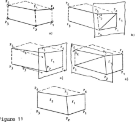
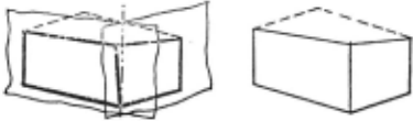
'z nte intersection of the tlrlO planes fl am f 2 forms the final vertical edge of the cube fig. 12) . After that, all coordinates are changed so that they fit with the equations of the planes.
4. 3 Data structure
With the CCilpU.ted points and planes a three dimen sional, hierarchical, ring oriented data structure is generated. The CXXTplexity of objects is restric ted to a maxi.mtJn of 200 points, 200 edges am 60 planes, where up to 10 edges are allONed to touch the same point.These restrictions are given by the limited lrlOrking storage capacity of the crnputer. In addition, the experimental system contains parts for mainpulating data structures (rotation, trans lation, scaling) and presenting them on a display.
4.4 Classification of three dimensional objects
The last block in the experimental system is for med by a classificator which crnpares data struc tures of known objects against the description of an unknown input object. nte features for classi fication are:
- the number of planes
- the type of planes (e .g. number of edges)
- the orientation of planes
- the relative length of edges
- the three dimensional coordinates of the comer points.
In order to be able to classify three dimensional objects it is ultimately necessary to be irrlepen dant of the given orientation of the object in the scene .. Therefore classification must be done in variant to rotation and translation of obj ects. By control of parameters the user is able to spe cify size invariant or size sensitive classifica tion. Furtherrrore he can get results dealing with scaling and distortion of objects. Fig.13 shows an exarrple of data structures presented on a dis play together with the result of a classification: DREIBEIN was identified to be the same object as DREIB10 and DREIB11.
nte classification process itself i s done by ro tating, translating and scaling the unknown object until it fits with one or more of the known ob jects. The classification is very quick: To iden tify the object Dreibein in fig . 13, the CDC 3300 requires about 0. 8 seconds.
@inproceedings{ijcai1975p105,
  title     = {Methods For Analyzing Three Dimensional Scenes},
  author    = {Roecker, F. and Kiessling, A.},
  booktitle = {Proceedings of the Fourth International Joint Conference on
               Artificial Intelligence, {IJCAI-75}},
  publisher = {International Joint Conferences on Artificial Intelligence},
  editor    = {Patrick Winston and Carl Hewitt},
  pages     = {669--672},
  year      = {1975},
  note      = {Visual Information Processing},
  url       = {https://ijcai.org/proceedings/1975/105},
}
TY - CPAPER TI - Methods For Analyzing Three Dimensional Scenes AU - Roecker, F. AU - Kiessling, A. T2 - Proceedings of the Fourth International Joint Conference on Artificial Intelligence, IJCAI-75 PB - International Joint Conferences on Artificial Intelligence PY - 1975 SP - 669 EP - 672 UR - https://ijcai.org/proceedings/1975/105 ER -Copied
Machine-readable versions of this paper, for tools and AI agents:





