Rule-based Contact Monitoring Using Examples Obtained by Task Demonstration
Proceedings of the Fifteenth International Joint Conference on Artificial Intelligence. Diagnosis and Qualitative Reasoning. Pages 514-520.
Abstract
This paper presents a new rule-based hybridsystem approach to contact monitoring. The rules are formulated in terms of temporal sequences of the contact force and they recognize temporal patterns of force associated with contact states and transitions. The rule-base is built using inductive learning techniques on force data obtained by human demonstration. This approach is suitable for monitoring robotic as well as human tasks. An advantage of this approach is that it allows process monitors for different tasks to be built quickly and easily by learning new sets of rules from a demonstration of the tasks. Experimental results are presented to demonstrate the effectiveness of this approach.
- [Asada and Hirai, 1989] H. Asada and S. Hirai. Towards a symbolic-level feedback: Recognition of assembly process states. In 5-th International Symposium on Robotics Research, Tokyo, 1989.
- [Barr and Feigenbaum, 1981] A vron Barr and Ed- ward A. Feigenbaum, editors. The Handbook of Artificial Intelligence: Vol I.
- William Kaufman, Inc., 1981.
- [Biermann anci Feldman, 1972] A. W. Biermann and J. A. Feldman. On the synthesis of finite-state ma- chines from samples of their behavior. IEEE Transac- tions on Computers, C-21:592-597, June 1972.
- [Bruyninckx et al., 1995] H. Bruyninckx, S. Dutre, and J. De Schutter. Peg-on-hole: A model based solution to peg and hole alignment. In IEEE International Conference on Robotics and Automation, pages 1919- 1924, 1995.
- [Delson and West, 1996] Nathan Delson and Harry West. Robot programming by human demonstration: Adaptation and inconsistency in constrained motion. In IEEE International Conference on Robotics and Automation, 1996.
- [Eberman and Salisbury, 1994] Brian Eberman and J. Kenneth Salisbury, Jr. Application of change de- tection to dynamic contact sensing. The International Journal of Robotics Research, 13(5):369-394, October 1994.
- [McCarragher and Asada, 1993] Brenan J. McCar- ragher and Haruhiko Asada. Qualitative template matching using dynamic process models for state transition recognition of robotic assembly. The ASME Journal of Dynamic systems, Measurement and Control, 115(2A):261-275, June 1993.
- McCarragher and Asada, September 1995]
- Brenan J . McCarragher and Haruhiko Asada. The discrete event modeling and planning of robotic assembly tasks. The ASME Journal of Dynamic systems, Measurement and Control, 117(3):394-400, September September 1995.
- [Ramadge and Wonham, 1989] Peter J. G. Ramadge and W. Murray Wonham. The control of discrete event systems. Proceedings of the IEEE, 77:81-98, 1989.
- [Sikka and McCarragher, 1996] Pavan Sikka and B.re- nan J. McCarragher. Monitoring contact using clus- tering and discriminant functions. In IEEE Interna- tional Conference on Robotics and Automation, 1996.
- [Stiver and Antsaklis, 1992] James A. Stiver and Panos J. Antsaklis. Modeling and analysis of hybrid control systems. In Proceedings of the 31st Conference on Decision and Control, pages 3748-3751, 1992.
- [Wang et al., 1996] Qi Wang, Joris De Schutter, Wim Witvrouw, and Sean Graves. Derivation of compliant motion programs based on human demonstration. In IEEE International Conference on Robotics and Au- tomation, pages 2616-2621, April 1996.
- [Whitney, 1982] Daniel E. Whitney. Quasi-static assem- bly of compliantly supported rigid parts. The ASME Journal of Dynamic systems, Measurement and Con- trol, 1982.
- [Williams and de Kleer, 1991] B C Williams and J de Kleer. A theory of interactions: Unifying qualitative and quantitative algebraic reasoning. Artificial Intelligence, 51:1-79, 1991.
References were extracted automatically from the PDF and may contain errors.
Full text extracted automatically from the PDF; figures, tables and equations may differ. The PDF is the version of record.
1 Introduction
Robotic systems are prone to errors due to uncertain ties in the model of the process and of the environment. This makes process monitoring an important part of a robotic system. Process monitoring is based on contin uously observing and interpreting the data from sensors that report on the system state, and is used for error de tection, recovery, control, adaptation and learning. The focus of this paper is the design of process monitors using inductive learning techniques within a hybrid dynamic systems framework.
Robotic tasks can often be modeled as hybrid dynamic systems [Stiver and Antsaklis, 1992]. A task level de scription is based on discrete event dynamic systems [Ra madge and Wonham, 1989], while the physical aspects of the system are modeled using continuous variable dy namic systems. In this hybrid dynamic systems frame work, a process monitor is defined as a mapping that transforms the physical state of the continuous system into discrete states and events at the task level. This approach can be contrasted with statistical change detection techniques for contact tasks. For example, Eber man and Salisbury [Eberman and Salisbury, 1994] con sider a temporal sequence of the force signal to deter mine contact type; however, there is no consideration of a discrete-event task model and their approach is fo cused on the continuous variable representation. This paper presents a rule-based method for contact monitor ing where temporal sequences of quantized continuous variables are matched with rules to determine the states and transitions of the d.iscrete-event system.
Task demonstration has been used for task-level robot programming. Delson and West [Delson and West, 1996] considered the problem of robot programming from demonstrated motion during one task-level state and did not address the problem of contact monitoring. Wang et al. [Wang et al., 1996] present a method to derive compliant motion programs from human demonstration. However, an explicit discrete-event model of the task is not considered, and hence the subtasks cannot always be identified with task-level states. In our approach, the rules are obtained from data generated by several demonstrations of the task being considered. The data obtained from demonstration is clustered into a small number of groups corresponding to quantized values of the continuous variables. Inductive learning techniques are then applied to the discretized data to obtain rules for monitoring and classifying the discrete states and events of the hybrid system. Since the rules pertain to both discrete states and events, this approach exploits the dynamics of the task, as opposed to previous work in assembly based on the quasi-static assumption which ig nores dynamic effects (see, for example, [Whitney, 1982; Bruyninckx et al., 1995]).
Our approach to obtaining the rules from examples can be contrasted with the model-based approach in [Mc Carragher and Asada, 1993] where qualitative reasoning techniques are used to obtain simple templates for re conizing contact state transitions. There is only one tem plate for each contact state transition. The templates are based on the current values of quantized variables and do not consider temporal sequences. Furthermore, qual itative reasoning techniques are difficult to apply consis tently to continuous dynamic models since it is difficult to obtain consistent qualitative algebras [Williams and de Kleer, 1991].
There are several advantages of this approach. Since the analysis is based on real sensory data, the approach has the advantage of taking into account various task pa rameters such as friction, which are difficult to model an alytically. Most important, the approach can be adapted easily and quickly to different tasks by simply learning new sets of rules from the data obtained by task demon strations. Since the learning phase is based on a demon stration of the task, this approach is applicable both to robotic process monitoring and to the study of human demonstration of tasks. Finally, our approach is general in that it can be applied to one or more sensory modal ities taken together, for example position and force.
2 Contact Monitoring using a Hybrid System Model
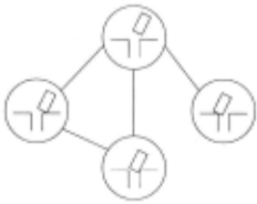
We consider contact tasks, such a.c:; assembly, to illus trate our approach to process monitoring. An example of modeling ari assembly task as a hybrid dynamic sys tem is presented in [McCarragher and Asada, September 1995]. These tasks can be characterized by the differ ent configurations of contact between the parts being assembled. The configurations are described geometri cally in terms of contact between the edges and surfaces of the objects involved and are called contact states. The contact states are organized into a graphical structure G = (r, E), called the contact state network, where r is the set of nodes representing the contact states 1 and E is the set of arcs connecting contact states and rep resenting the allowed changes in contact states [Asada and Hirai, 1989]. This is illustrated in Figure 1, which shows a part of the contact state network correspond ing to the planar peg-in-hole task. At the plant level, the contact states determine the geometrical constraints which, together with the equations of motion, determine the plant behavior in terms of state variables such as position, velocity, acceleration, and force.
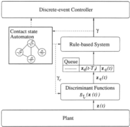
The contact monitor tracks the state of the continuous plant by monitoring variables of interest such as the po sition of the robot and the force acting on the robot. The organization of the contact monitor within the hybrid dynamic framework is shown in Figure 2. The system is modeled as a combination of a continuous-domain sys tem interacting with a discrete-event system through an interface. The interface acts as a mapping between the two sub-systems, transforming and inter-connecting the discrete and continuous inputs and outputs between the two sub-systems. Within this framework, the transfor mation between the discrete event system and the continuous system becomes a key issue, and the process monitor is represented as a part of the interface. The vector z(t) denotes the state of the plant as seen by the process monitor, and consists of variables that are of in terest to the process monitor. For example, in the planar case with force and changes in force being the variables of interest, z(t) = [fx(t) , fy(t), ix(t), jy(t)J\ where fx and f y denote the planar components of force.
The contact monitor works in two steps. In the first step, the process monitor samples the variable z and then quantizes or discretizes it into the variable Zq · For example, in an assembly task, Zq = [fxq, fyq, f~q, f~q]t. The discretization is performed using discriminant func tions g'Yc based on the current contact state 'Yc· The discriminant functions are also obtained from the data generated by human demonstration. The details of this step can be found in [Sikka and McCarragher, 1996].
The second step of the process monitor consists of us ing a rule-based system [Barr and Feigenbaum, 1981] to identify the process state 1 ba.c:;ed on a sequence of dis cretized variables. This process is described in detail in the next section.
3 Rule-based Contact Monitoring
Each contact state transition can be characterized by temporal patterns of force. These patterns can easily be encoded in the form of rules for identifying the cor responding contact state transitions. This observation is the basis for our approach to rule-based contact state and transition identification.
A rule is defined as a condition-action pair where the condition part specifies the conditions under which the rule can be applied and the action part specifies the ac tions that are taken when the rule is applied. For exam ple, in the context of contact monitoring, the following general rule can be used for recognizing a contact state transition:
IF
state = /l AND
Here, k refers to the current sampling period, d1 · · · d3 refer to the discrete values of the quantized variables and /1,/2 E r denote contact states. To simplify notation, the remainder of this paper uses the corresponding inte gers i to refer to the discrete values di.
The rule shown above checks for a sequence of dis cretized values of the rate of change of force to recognize a transition from contact state 11 to /2. In general, sev eral variables are monitored and the rule-based process monitor consists of sets of rules for each variable and for each contact transition. This leads to a very general system for monitoring contact.
There are several important issues for rule-based sys tems. The matching of rules to data is computationally expensive [Barr and Feigenbaum, 1981]. A large rule base coupled with a large database can make the system too inefficient to be of use. Another important issue for rule-based systems is the integrity of the rule-base. A rule-base with conflicting rules can lead to ambigu ous results, and hence the rule-base must be checked for conflicts. These problems are addressed in the paper by the choice of finite-sate machines as the representation for rules and by the organization of the rule-base using the contact state network.
3.1 Finite-state machines: a representation for rules
A finite-state machine (FSM) is defined as the structure M = { S, L: , j, so, F}, where S is the set of states, ~ is the set of input symbols, f : S x L: --+ S is the state transition function, so E S is the initi~l state, and F ~ S is the set of final, accepting states. A FSM operates as follows: The state of the machine is initialized to s0 . The input to the machine consists of a sequence IJ of symbols taken from the input alphabet L: of the FSM. The input string is processed sequentially. Thus, if IJ; is the next unprocessed symbol in the input, and s is the current state of the FSM, then the FSM changes its state to f(s , tJi) and IJi+1 becomes the next symbol to be processed. The FSM stops after processing the last symbol in the input string. Let St be the state of the FSM when it stops. If St E F, then the FSM is said to accept the string IJ.
A set of rules can be represented by a FSM under certain conditions. In particular, pattern classification rules can be easily implemented as a set of FSMs with one FSM for each set of patterns representing a class. The input alphabet of the FSM consists of the symbols used to express the patterns. A path from the initial state to a final state of the FSM corresponds to a pattern belonging to the corresponding class, and hence to a rule for that class.
The representation of a set of rules by a FSM signif icantly reduces the computational effort required to de termine the rules that apply to the current information in the database. For a given pattern in the database, the task of finding the matching rule is reduced to de termining if the FSM accepts the sequence representing the pattern.
3.2 The contact monitor
Let { Zq ( k)} denote a temporal sequence of the dis cretized plant state vector. When this sequence cor responds to a contact state transition, it can be used to characterize the particular transition. In general, a contact state transition can be characterized by a set of temporal sequences or patterns of the discretized plant state vector Zq. Thus, each component of Zq contributes an associated set of patterns for a given contact state transition. Each pattern becomes a rule for recogniz ing the corresponding contact state transition and these rules together are encoded as a FSM for recognizing the given transition.
The contact monitoring system is built around the contact state network G. Let e1 , · · · , ep represent the transitions allowed from a contact state 'Y· As be fore, let the discretized plant state vector be definedby: zq(k) = fq(k) = [fxq(k), /yq(k), f~q(k ), f;q(k)Ji. Then, for a transition e from '' a set of 4 FSMs are defined, one for each discretized variable: M 1 e , M 1 e , Me. and xq yq f x q Mfe .. yq The rule-based contact monitor works as follows: Let { .. ·,fq(j), .. ·,fq(k)} denote the sequence of values of the discretized plant state vector. Then, the input strings for the FSMs consist of the sequence { fq ( k - mD.), .. · ,fq(k- D.),fq(k)}, where D. is an integer rep resenting a system-dependent delay and m is an integer representing the the system-dependent sequence length. The sequence of each discretized variable is used as the input for the corresponding FSM. The transition for which all the FSMs accept the input sequence is taken as the transition occurring at instant k. The parame ters m and D. in the input sequence are chosen based on the considerations such as the computing power available and the sampling rate. For example, in the implemen tation described later in the paper, the sampling rate is 120 Hz and typically about 60 samples make up a tran sition. The computing resources limit m to 5. Hence, to represent the tran~itions, D. is chosen to be 12.
Organizing the FSMs according to the contact state network has the advantage of simplifying the problem of determining the consistency of rules. The rules corre sponding to transitions from a contact state can be ex amined independently of transitions from other contact states. Furthermore, for a given state, conflicts may ex ist among rules for a particular variable as long as there are no conflicts when the rules for all the variables are considered together.
4 Contact monitoring and human demonstration
This section addresses the problem of constructing a con tact monitor for a given task. This involves several steps. First, the contact state network must be constructed and the variables making up the plant state vector must be specified. Then, for each state, the discriminant func tions for quantizing the plant state variables need to be specified. Finally, the FSMs corresponding to the rules associated with each contact state transition must be constructed. In this section, we describe the use of task demonstration to construct the discriminant functions and the FSMs for the given task. The problem of con structing the contact state network for a given task is not addressed in this paper.
A person demonstrates the task several times. Vari ables constituting z(t), like position and force, are recorded during each demonstration of the task. Thus, human demonstration of the task yields a set of traces of the plant state z, denoted by {y1 , · · ·, Yp}, where Yi = {z(k)}. Each trace Yi is used to generate sub-traces Yij corresponding .to the individual contact state transi tions present in the trace. This must be done manually, although automatic change detection algorithms, for ex ample [Eberman and Salisbury, 1994], can be used to aid in this process. These sub-traces are then organized ac cording to contact states. Thus, the set X-y, contains all the subtraces corresponding to contact state transitions from the contact state It ·
The next step in setting up the contact monitor is to discretize the traces obtained from human demonstra tion. The discretized sequences are then used to obtain the discriminant functions as well as the rules for the contact monitor. For each state /i, the sub-traces in X-y; are combined into one large set of data points X. Using clustering techniques, the points in X are then grouped into a small number of classes for each component of the plant state vector z. These classes correspond to the discretized values for the variable. In this manner, the clusters are then used to learn the discriminant functions for each of the variables and for each contact state. This process is described in detail in [Sikka and McCarragher, 1996].
Finally, the rules for contact state and transition recognition must be obtained from the clustered data. First, for each state /i, the clustered data is regrouped into sub-traces corresponding to the sub-traces in the set X-y; to obtain the set of sub-traces Xq-y;. Then, for each variable in z, the sub-traces in Xq-y; are used to obtain examples of the corresponding contact state transition. This step is due to computational considerations and is required to reduce the length of long temporal sequences generated as a result of high sampling rate. Thus, we fi nally obtain the sets X~-y; corresponding to each contact state /i and containing examples of contact state tran sitions.
In the last step for setting up the contact monitor, the sets X~-r; are used to learn the FSMs for each variable in z. The FSM generated for each variable recognizes ex actly the set of examples used. The FSM is constructed using the algorithm described in [Biermann and Feld man, 1972]. This algorithm constructs an FSM given a set of examples in an iterative manner, with each con structed FSM closer to the given set. The algorithm is based on progressively identifying longer and longer prefixes that are present in the given set of examples.
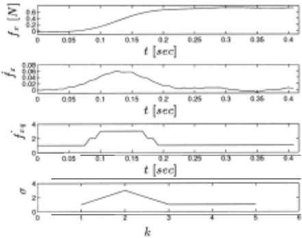
The approach is illustrated in Figures 3 and 4. Fig ure 3(a) shows the raw signal corresponding to a gain of contact. The first-difference for this signal, corre sponding to the time-derivative, is shown in Figure 3(b ). This signal is then clustered into 4 discrete values to ob tain the discretized first-difference signal shown in Fig ure 3( c). Finally, Figure 3( d) shows the input string of length 5 obtained by further sampling the discretized signal, 13111. Such input strings are obtained for each demonstration of the particular contact state transition to generate a set of input strings, for example, {13111,
]
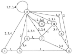
14111, 11311, 11411, 11131, 11141 }. Figure 4 shows the FSM obtained for this set using the algorithm described in [Biermann and Feldman, 1972]. The FSM consists of 9 states, with the state labeled 1 being the initial state s0 , and the state labeled 9 being the only accepting state, i.e., F = {s9}.
5 Experimental Results
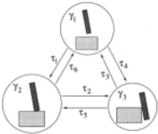
The rule-based process monitor was tested on a task con sisting of several contact states resulting from contact between a rectangular peg and a solid block. These con tact states are illustrated in Figure 5 and are denoted by 11, /2 and /3. Figure 5 also shows the contact state net work for the experimental setup, and the allowed transi tions 71 · · · 76 between the contact states. The task used to test the process monitor consists of the sequence of contact states /1 -+ /2 -+ /3 -+ /1 -+ /3 -+ /2 -+ /1·
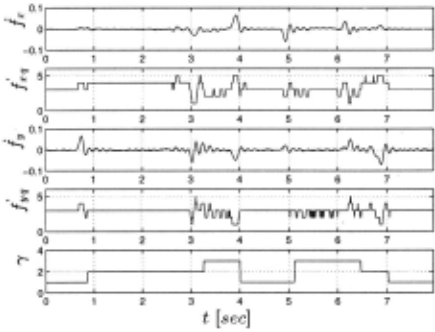
The task was demonstrated several times by a person and the data from three demonstrations was used to set up the rule-base of the process monitor as described in Section 4. Figure 6 shows the output of the two stages of the process monitor used during a task demonstration.
The topmost graph in Figure 6 shows ix, the derivative of the force acting tangential to the top surface of the solid block. The second graph shows the discretized vari able ixq produced by the process monitor. Similarly, the third and fourth graphs relate to the force in the normal direction. The graph at the bottom of Figure 6 shows the discrete events recognized by the rule-based process monitor.
The performance of the contact monitor was measured by using it to monitor 25 demonstrations of the task de scribed above. The percentage of transitions recognized correctly by the rule-based process monitor is summa rized in Table 1 which shows the overall recognition ac curacy for the task and the recognition accuracy for each individual transition. The first set of numbers in Table 1 show the performance after initially training the rule base using 3 demonstrations. However, note that the recognition accuracy of the process monitor for transi tion 72 from contact state 12 to 13 is very poor at 48 %.
Closer examination of the data revealed qualitative differences corresponding to this transi~ion. The con tact monitor was therefore changed by replacing one of the demonstrations in the training set and then obtain ing a new set of rules for the rule-base. The second set of numbers in Table 1 show the recognition accuracy of the process monitor based on the new rule-base. The Table shows that the recognition accuracy of the process monitor for transition 72 improved to 72 % and the over all recognition accuracy also improved to 84.5 %. This demonstrates that the process monitoring system is very flexible and changes can easily be made to improve per formance.
| I 71 | I 72 | I 7J | I 74 | I 7s | I 76 | I All |
|---|---|---|---|---|---|---|
| After initial training | ||||||
| I 100 | I 48 | I 75 | I 68 | I 93 | I 100 | I 79 |
| After retraining | ||||||
| I 100 | I n | I 61 | I 83 | I 93 | I 95 | I 84.5 |
6 Conclusion
We have presented a new rule-based method for process monitoring within the framework of hybrid dynamic sys tems, based on human demonstration. The experimental results indicate that this method is effective and captures the dynamic nature of the sensory data corresponding to gain and loss of contact. Thus, rule-based transition detection, together with pattern recognition based tech niques of discriminant functions and clustering methods, provide a flexible and robust method for robotic process monitoring.
@inproceedings{ijcai1997p76,
  title     = {Rule-based Contact Monitoring Using Examples Obtained by Task Demonstration},
  author    = {Sikka, Pavan and McCarragher, Brenan J.},
  booktitle = {Proceedings of the Fifteenth International Joint Conference on
               Artificial Intelligence, {IJCAI-97}},
  publisher = {International Joint Conferences on Artificial Intelligence},
  editor    = {Martha E. Pollack},
  pages     = {514--520},
  year      = {1997},
  note      = {Diagnosis and Qualitative Reasoning},
  url       = {https://ijcai.org/proceedings/1997/76},
}
TY - CPAPER TI - Rule-based Contact Monitoring Using Examples Obtained by Task Demonstration AU - Sikka, Pavan AU - McCarragher, Brenan J. T2 - Proceedings of the Fifteenth International Joint Conference on Artificial Intelligence, IJCAI-97 PB - International Joint Conferences on Artificial Intelligence PY - 1997 SP - 514 EP - 520 UR - https://ijcai.org/proceedings/1997/76 ER -Copied
Machine-readable versions of this paper, for tools and AI agents: