
A Pictorial Approach to Object Classification
Proceedings of the Twelfth International Joint Conference on Artificial Intelligence. Vision. Pages 1257-1262.
© 1991 International Joint Conferences on Artificial Intelligence
Abstract
This work uses an alignment approach for classifying objects according to their shape similarity. Previous alignment methods were mostly limited to the recognition of specific rigid objects, allowing only for rigid transformations between the model and the viewed object. The current work extends previous alignment schemes in two main directions: extending the set of allowed transformations between the model and the viewed object, and using structural aspects of the internal models, namely, their part decomposition. The compensating transformation is divided into two parts. The first, rough alignment, compensates (approximately) for changes in viewpoint and is derived by matching tangential points on the silhouette of the model and the viewed object. The second, the adjustment transformation, is derived by matching local features - discontinuities of the contour orientation and curvature. Principal aspects of the scheme suggested here are also relevant for the recognition of flexible objects.
- F. Attneave. Some informational as- pects of visual perception. Psychological Review, 61 : 183-193, 1954.
- Bajcsy and Solina 1987]
- R . Bajcsy and F. Solina. Three dimensional object representation revisited . Proc. ICCV'87, 231-240, 1987.
- Basri and Ullman 1988]
- R. Basri and S. Ullman. The alignment of objects with smooth surfaces. Proc . ICCV'88, 481-487, 1988.
- Besl and Jain 1985]
- P. J . Besl and J. C. J ain . Three- Dimensional Object Recognition. Computing Sur- veys, 17: 75-145, 1985.
- Biederman 1985]
- I. Biederman. Human image under- standing: Recent research and a theory. Comp. Vi- sion, Graphics and Image Process., 32: 29-73, 1985.
- Chin and Dyer 1986]
- R.T. Chin and C . R. Dyer . Model-Based Recognition in Robot Vision. Com- puting Surveys, 18: 67-108, 1986.
- Faugeras and Hebert 1986]
- D. Faugeras and M. Hebert . The representation, recognition, and loca- tion of 3-D objects. Int. J. Robotics Research, 5:(3), 27-52, 1986.
- Fischler and Bolles 1981]
- M. A. Fischler and R.C. Bolles. Random sample consensus: A paradigm for model fitting with application to image analysis and automated cartography. Comm. of the A CM, 24: 381-395, 1981.
- Hoffman and Richards 1984]
- D. D. Hoffman and W . A. Richards. Parts of recognition . Cognition, 18: 65- 96, 1984.
- Koenderingk and Van Doorn 1979]
- J. J . Koenderingk and A. J. Van Doorn. The internal representation of solid shape with respect to vision . Biological Cy- bernetics, 32: 211-216, 1979.
- N. K. and Zucker 1988] N. K. Link and S. W . Zucker . Corner detection in curvilinear dot group- ing. Biological Cybernetics, 59: 247-256, 1988.
- D. G . Lowe. Perceptual organization and object recognition . Boston: Klwer A cademic Pub- lishers.
- Marr and Nishihara 1978]
- D. Marr and K. Nishihara. Representation and recognition of the spatial orga- nization of three dimensional shapes . Proc. of the Royal Society -London B, 200: 269-294 , 1978.
- Newport and Bellugi 1978]
- E . L. Newport and U. Bellugi. Linguistic expression of category lev- els in a visual-gestural language. In: E. Rosch and B . B . Lloyd, Cognition and Categorization. Lawrence Erlbaum Assoc., Hillsdale, NJ , 1978.
- Palmer et.al. 1981]
- S. E . Palmer, E. Rosch, and P. Chase . Canonical perspective and the perception of objects. Attention and Performance IX (Long and Baddeley, Eds.). Erlbaum, Hilsdale, NJ, 1981.
- Rosch et.al. 1976]
- Rosch E . et.al . . Basic objects in nat- ural categories. Cog. Psych. , 8: 382-439, 1976.
- Shapira 1990
- Y. Shapira. A pictorial approach to ob- ject classification and recognition across shape changes. Weizmann Inst . of Science, Dept . of App. Math., Ph.D. Thesis , 1990.
- S. Ullman . Aligning pi ctorial descrip- tions: An approach to object recognition. Cogni- tion, 32(3): 193-254, 1989.
References were extracted automatically from the PDF and may contain errors.
Full text extracted automatically from the PDF; figures, tables and equations may differ. The PDF is the version of record.
1 Introduction
Object recognition is a process of establishing a corre spondence between a viewed object and an internal rep resentation of a previously known one. The recognition process can rely on different cues, and its results can be at different levels of specificity. The same object can be recognized, for instance, as a furniture, a chair, or the particular chair in my office. An adequate defini tion of the problem addressed by a recognition method must therefore include the cues the method relies on, and the specificity level at which the answer is expected. Re cent reviews of many of the methods proposed for object recognition can be found in [Besl and Jain 1985; Chin and Dyer 1986; Ullman 1989).
·The research described therein was preformed in The Weizmann Institute of Science, Rehovot, Israel.
t S. U. was supported in part by NSF grant IRI 8900267.
Shimon Ullman t
Dept. of Brain and Cognitive Science Massachusetts Institute of Technology Cambridge, MA 02139, USA;
Dept. of Applied Mathematics
Weizmann Inst . of Science, Rehovot, Israel
E-mail: shim@ai.mit.edu
In this paper we address several aspects of classifying objects at their so-called "basic object" level, relying on similarities of their visual shape. Basic object classifi cation is the name we normally use spontaneously to describe an object. A category at this level usually has a one word name with no one word subclasses, such as a "chair" as opposed to "furniture" and a "kitchen chair". Categorization at this level has been shown by several re searchers [Rosch et. a/. 1976; Newport and Bellugi 1978) to be achieved faster than at other classification levels. Furthermore, Rosch and her collaborators [Rosch et. a/. 1976) have also shown that shape similarity among class members is more significant at the basic object level than at other possible levels [Rosch et.al. 1976, pp. 398-405) , indicating that this level is a natural domain for classifi cation methods based on shape similarity. These findings also suggest that the procedures used for classification should be relatively fast and simple compared to those used for a more detailed level of recognition.
In the method proposed in this paper object classes are represented by single prototypes [Rosch et.al. 1976; Bajcsy and Solina 1987). The differences between class members are considered as deformations of the shape of the stored prototype. Therefore, the proposed classifi cation method applies in many respects also to objects that can actually undergo non-rigid deformations (e .g., animals, plants, etc.).
The classification method belongs to the family of alignment methods, as presented recently by a num ber ofresearchers [e.g., Fischler and Bolles 81; Lowe 85; Faugeras and Hebert 86; Ullman 1989]. Some of these methods employ pictorial models as the internal repre sentation of the objects that are to be recognized. The models can be, for instance, the edge map of an image of these objects, augmented with some depth informa tion [Basri and Ullman 1988]. The alignment method proceeds by compensating for the transformation sepa rating the viewed object and the stored model. A small number of special features ci:m be extracted from the im age and used to derive the transformation required for aligning the model with the image. Since the identity of the viewed object is not known at this stage, this align ment transformation is deduced for, and applied to, all the relevant stored models. After this alignment stage, the correct model is expected to be significantly more similar to the image object than any of the competing internal models. A simple comparison procedure in the subsequent stage, such as a simple correlation, will then be sufficient to indicate the correct model.
The pictorial nature of the representation used in the alignment approach (as opposed to more abstract at tributes) and the exact alignment transformations that are derived, make the approach suitable for recognizing specific rigid objects. Alignment methods have been ap plied to recognize both flat and solid objects, yielding encouraging results (e.g., Fischler and Bolles 81 ; Lowe 85; Faugeras and Hebert 86; Basri and Ullman 88].
1.1 An Extended Set of Compensating Transformations
Alignment methods for object recognition have been ap plied in the past to rigid or almost rigid objects. To cope with shape changes associated with different members of a given class, two major extensions have been intro duced to the basic alignment method. The first is using a broader set of transformations than the rigid motion and uniform scaling used for rigid object recognition. Such a set should compensate for two types of differences be tween the viewed object and its stored model : changes in viewpoint, and possible shape differences between the stored prototype and another member of its class.
The components of the compensating transforma tion associated with these two sources of variations are treated separately. A simplified procedure, called rough alignment, is used for compensating for viewpoint dif ferences between the internal models and the object in the image. The accuracy of this alignment is consider ably lower than the alignment used in recognizing rigid objects. This version is particularly adequate, however, when the alignment is followed by a second stage of com pensating transformation. Such a simple process of pre liminary alignment may also be useful for a variety of recognition schemes, other than the one presented be low.
The role of the second stage of the compensating trans formation is to account for actual shape differences be tween the viewed object and the (prototype) model. This part is denoted as adjustment. In principle, it might have been useful to associate with each of the internal proto types a minimal set of allowed transformations. Such a minimal set would account for all possible members of the modeled class and at the same time exclude all non-member objects. However, it is difficult to prede fine such a minimal set of transformations. Although the set of transformations relating one position of, e.g., scissors to another is feasible, what would be the trans formations that relate all possible positions of a shirt , or different types of chairs? This suggests a different approach: allowing liberal and flexible general deforma tions, and then assessing the distortion that was required in order to bring each of the models and the image into correspondence.
The general scheme for aligning a stored prototype with a viewed object is therefore the following. First, a rough alignment procedure is used to compensate ap proximately for changes in viewing position. In a second stage, more flexible and general distortions are used to bring each candidate model into correspondence with the image. The amount of distortion required at this stage will be used to asses the quality of match.
1.2 The Internal Representation of Object Classes
Alignment schemes for rigid object recognition usually employ pictorial, unarticulated internal models . The current classification scheme has been extended, to spec ify explicitly the principal parts of the model. The pur pose of adding the object's part decomposition to the pictorial representation is to obtain a convenient and natural control of the deformations that are allowed for these models. Many of the allowed deformations are eas ier to specify in terms of relatively simple changes that may be applied to parts of the objects. The model used for the "car" class of objects, as well as its part decom position, are shown in Figure 1.
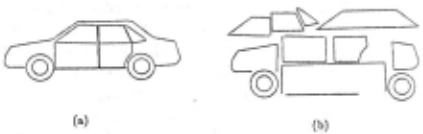
Relying on the part decomposition of objects for their recognition is usually associated with methods that em ploy a more structural approach to recognition (e. g., (Marr and Nishihara 1978; Biederman 1985; Bajcsy and Solina 1987]). There are two major differences between these methods and the one presented here. The first is that parts are defined here only in the internal model and are not extracted from the image. This is advantageous since bottom-up processes for extracting object parts are often difficult and unreliable. The second difference con cerns the expressive power of the internal representation being used. We only use parts as means of controlling and restricting the applied deformations. The eventual comparison between the models and the viewed object relies on complete pictorial descriptions that are not re stricted by the use of any predetermined set of generic shapes or geometrical relations .
Two dimensional models are used in our scheme to represent the object classes. Using a finite number of two dimensional models is not sufficient for representing all views of a general solid object (even when using an alignment transformation). Part of the inaccuracies re sulting from the "flatness" of the models are expected to be corrected by the second part of the compensating transformation, namely, the adjustment .
Finally, we point out that a parametric line represen tation is used in the implemented scheme for describing both the viewed images and the internal models . The representation, consisting of straight line segments and circular arcs, is not obtained in an all-automatic proce dure; it involves at present some user interaction.
The subsequent sections are organized as follows. Sec tion 2 describes the process of rough alignment. In Sec tions 3 and 4 we describe a method used for establishing correspondence between points of orientation disconti nuity in the model and the image, and. using this cor respondence for extracting the appropriate adjustment transformation. Finally, Section 5 discusses various pos sibilities for evaluating the overall degree of match be tween the models and the viewed object and examines one of them in detail.
2 Rough Alignment
2.1 Approximating 3-D by 2-D Transformations
The role of the rough alignment part of the compensat ing transformation is to account (approximately) for the viewpoint differences. Due to its simplicity and robust ness to partial occlusions, such a procedure is also ap propriate as a preliminary transformation stage for other recognition methods.
Rough alignment is different from what would be a perfect alignment of the internal representation with the viewed object in two ways. The first difference is that the procedure can only be applied for a restricted range of in-depth rotations (i.e., about an axis in the image plane) of the particular internal model. Typically, this range is ±30°. Limiting the value of the in-depth ro tation avoids the need to eliminate hidden lines. As discussed bellow, it also allows to approximate the ac tual (3-D) rigid object transformation by a simpler, 2-D one. Such viewer centered models have also been used for rigid object recognition [e.g., Koenderingk and Van Doorn 1979; Basri and Ullman 1987) and are supported by psychological evidence [e.g., Palmer et.a/. 1982).
The second difference is conceptual in nature. For rigid objects viewed from different positions, the notion of correct alignment is well defined. For objects that undergo shape changes as well as changes in viewpoint, the "correct" alignment transformation is more difficult to define uniquely. In this case, the best 3-D alignment can be defined as the one that minimizes some global difference measure between all matched point pairs in the image and the model. Such an alignment transfor mation is difficult to compute and, due to possible shape changes, it also leaves many model points far apart from their image counterparts, preventing the immediate ap plication of a simple comparison between the model and the image.
A different approach, using a simplified procedure for extracting and applying an approximate alignment to 2D object models, is therefore proposed. The main goal of this simplified procedure is to facilitate the second part of the compensating transformation, namely, the adjustment.
To account for different types of shape changes, the adjustment transformation must be determined by many parameters. Extracting these parameters requires that many features be matched in the model and the image. This matching can be facilitated if, following the rough alignment, the viewed object and the candidate models, as well as their corresponding parts, would substantially overlap in the image plane (obviously, the requirement for overlap of corresponding parts may be meaningless for wrong models). When such an overlap is accom plished, points in the transformed model are likely to be close to their counterpart in the image object.
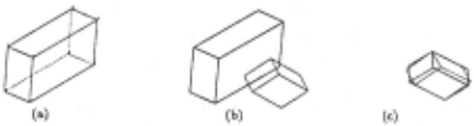
A two-dimensional "enhanced" similarity transforma tion is used for rough alignment. The transformation is determined by five parameters: two for translation, one for rotation, and two for scaling along two perpendicular axes- all within the image plane. The results of roughly aligning a box-shaped object using the enhanced 2-D similarity transformation are shown in Figure 2. Quali tatively, the situation following rough alignment seem to enable the use of a distance measure in matching model and image anchor features.
2.2 Anchor Features for Rough Alignment
The extraction of the rough alignment transformation can rely on partial information in the image using a small number of image features (called "anchors" for the transformation). Matching the center of mass and the two inertia moments of the model and the viewed ob ject, for instance, is sufficient for determining the five pa rameter of the enhanced similarity transformation. Al ternative anchors for this purpose are any combination of two matched points and a direction. We use local feature points labeled by global properties as the an chor features. Such a combination provides robustness against partial occlusions (unlike the case of relying just on global moments of the shape, for instance) without imposing an extensive search on matching the anchor features (as matching local features often does).
The global properties used to label the local anchor features are the bounding contour of the viewed object (also called the silhouette), and its prominent orienta tion. A simple algorithm is used to extract a rather primitive version of the silhouette. This version consists in associating a "silhouette" binary label to each image line which has no neighbors on one of its sides, along some portion of its length. The existence of neighbors is verified by examining possible intersections of rays ex tending from each image line, perpendicular to it, with other contours in the image. The silhouette found for an image of a car is shown in Figure 3{ a) .
There are a number of ways to define the prominent orientation in an image of an object . One possibility is to use the global inertia moments of the object's area. Similarly to other moments of the shape, however , such a definition is sensitive to partial occlusions. Other pos sible definitions may rely on common direction of texture elements, the direction of symmetry axes , or the common direction of long lines in the image.
Here we define the prominent orientation of the viewed object to be the most frequent orientation of the seg ments in its silhouette. Such a definition is both lo cal and, for many objects, it also agrees with the gen eral elongation direction. The prominent orientation ex tracted for a car image is shown in Figure 3{a) . This di rection corresponds to the highest peak in an histogram of the orientations of the segments in the object's silhou ette (where each contribution is weighted by the length of the segment).
Having a prominent orientation in the model and im age can be exploited by using orientation (relative to the prominent one) to label local features, such as end-points of long straight lines, orientation discontinuities, etc., and to facilitate their matching. We use the prominent orientation as reference for labeling tangential points on the silhouette according to their tangent orientation. To reduce the number of points that need be extracted in the image, they are marked on all of the internal models for a "standard" set of tangent orientations.
The tangential points extracted for four tangent orien tations (0°, 45°, 90°, and 135°) are marked in Figure 3{a) by small 'T'-s. They are extracted by sorting extremum contour points in the direction perpendicular to the set of tangent orientations. As demonstrated below, using the tangential points for extracting the rough alignment parameters can be made fairly robust against partial oc clusions. The implications of other possible sources of sensitivity, namely, in-depth rotations and shape changes are discussed elsewhere [Shapira 90).
2.3 Extracting the Rough Alignment Parameters
The difference between the prominent orientations of the viewed object and the internal model is used to deter mine the rotation parameter (within the image plane) . Then, a one-to-one correspondence is established be tween tangential points of the same orientation. The scaling factors along the prominent orientation of the model and along the direction perpendicular to it are de termined by comparing the respective components of the distance between pairs of (matching) tangential points . Having applied the appropriate rotation and scaling, the translation is determined by comparing the location of corresponding tangential points.
To avoid the effect of lateral displacement of the tan gential points (which may result from in-depth rotations, partial occlusions, and shape changes) both scaling and translation are determined only according to the per pendicular components of the tangential points. Pairs of tangential points contribute to a scaling factor only if the line joining them is roughly perpendicular to that of the tangent at both points. Similarly, each tangential point contributes only a translation component perpen dicular to its tangent orientation. The total translation vector is computed as the one that agrees best with all the perpendicular components that are contributed by the individual points.
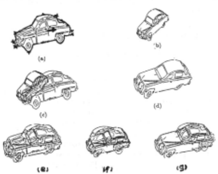
The result of applying the rough alignment algorithm to the different views of the same car is shown in Fig ure 3. One of the images 3{b) is taken as the internal model, while another image 3{a) is considered to be the viewed object . In the initial configuration the overlap between the image and model is small (3c). Following the rough alignment it increases significantly {3e), facil itating the subsequent adjustment stage. Figures 3{f,g) demonstrate the insensitivity to partial occlusions. A demonstration of what may be denoted as a "naive rough alignment" for an occluded version of the object in Fig ure 3(a), is shown in 3(f) . It relies on global moments such as the center of mass and the area. Comparing the latter figure with Figure 3{g) demonstrates that the results obtained by the rough alignment algorithm are significantly more robust to occlusions.
The procedure proposed here for rough alignment is thus simple and reliable. Applying it to the internal model yields an approximate, rather than a perfect align ment with the viewed object . This facilitates , however, the subsequent stage. In the next section we discuss the subsequent adjustment, assuming that the models are already roughly aligned with the viewed object .
3 Anchor Features for the Adjustment Transformation
3.1 Extracting Corners
The adjustment transformation (described in Section 4) is based on the extraction and matching of many fea tures (the anchors). In this section we describe briefly the extraction of one type of anchors, called "corners", which are points of discontinuity in orientation or curva ture. The significance of such points in image perception has been supported' by a number of studies (e.g., [At tneave 1954; Biederman 1985; Link and Zucker 1988]). Other types of anchor points, such as inflections and small blobs are also possible, but will not be discussed here.
Orientation and curvature discontinuities can be found by locating intersecting pairs of straight segments and circular arcs (by solving the appropriate equation sys tem). As lines in the parametric line representation often do not actually intersect, configurations in which lines "almost intersect" need also be considered. These in clude locations at which two co-terminating lines form a point of orientation discontinuity, as well as other con figurations such as points at which lines c~-terminate "almost" linearly, T-like junctions of contours, and con figurations in which a straight line is "almost" tangential to a circular arc.
The extent by which a given line segment may be extended to the intersection point is determined by a threshold that measures the quality of the resulting cor ner. This measure, V, was taken to be:
where /i is the length of the i-th line segment, and ci is the length by which it had to be continued to the intersection point (i = 1, 2). For "almost tangential" intersections, a third term, measuring the distance by which the straight line missed the circular arc, is added:
where r is the radius of the arc, and d the distance to the straight segment. Intersection points are accepted only for V values smaller than 0.5. Using this threshold for 'virtuality', about 200 corners were extracted from a typical object image (such as Figures 3(a) and 4(b)). Each corner is represented internally using its location, the angle it formed, its bisector, pointers to the image lines that generate it, and a silhouette label, reflecting the silhouette labels of its generating lines.
3.2 Matching Corners
The next stage in the adjustment process involves the matching of model and image corners. A subset of the model corners used in the adjustment phase is shown in Figure 4a. The corners matching proceeds in two stages. In the first, all the image corners compatible with each model corner are marked. The compatibility is determined by local parameters: distance between the corners, direction of bisectors, angle size, and silhouette labels.
In the second stage, the best matching image corner is selected from the set of compatible ones. This is ob tained by examining the degree of match between the generating lines of the model and each of the compatible image corners. For each image corner, the model corner is displaced and rotated in the image plane so that its location and bisector orientation would be identical to those of the image corner. Then, the mismatch between the generating lines of the model and image corner is evaluated, based on the fraction of matched portions of the lines and their residual misalignment (for the exact formula, see [Shapira 1990]).
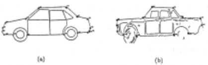
This procedure yields good matches for model and im age corners that lie on the silhouette of the object . The image counterparts found for the silhouette model cor ners in Figure 4(a) are shown in Figure 4(b). The results obtained for internal (non-silhouette) model corners are considerably inferior. The difference in performance for silhouette and internal corners is due to the nature of the silhouette label that cuts down significantly the number of compatible matches for silhouette, but not for inter nal, contours.
4 The Adjustment Transformation
Following the corner matching, an adjustment transfor mation is applied independently to each of the model parts. Each part is allowed to undergo an affine trans formation that will make it as similar as possible to a corresponding image part. The affine transformation is determined by six parameters, determining a displace ment and a linear transformation:
where ( x', y') are the coordinates of the transformed model point, originally located at (x, y), and (D,, Dy) is the translation vector . This transformation may be interpreted as the image plane projections of a planar object undergoing a general rigid motion in 3-D space. In general, the number of matched anchor points of each model part will be large enough to over-constrain the affine transformation parameters. In such a case, the affine transformation can be determined by computing the average displacements of the anchor points, and using pseudo inverse to determine the linear transforma tion.
The affine transformation is somewhat limited, and may not be sufficient to account well for the observed dis tortion. We have used instead a more flexible transfor mation, defined as follows. The part points that are close enough to a matched anchor point are translated in the image by the same displacement vector as the neighbor ing anchor. The remaining part points are transformed according to the affine transformation determined by all the matched anchors of that part. The resulting trans formation is more flexible, but its extent is still easy to evaluate by examining the parameters of the affine trans formation involved.
The result of applying this transformation to the model parts that lie on the silhouette is shown in Figures 5(a-c). It should be noted that using the line represen tation avoids the need to transform all the points that comprise the contours of a given model part, since it is straightforward to compute the effect of the affine trans formation on straight segments and circular arcs.
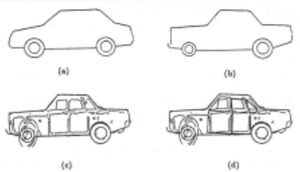
The above procedure applies only to points along the silhouette. The transformation must then be extended to internal contours as well. A possible means to this aim is to impose certain relations between the parts de fined in the model. Since deformation modes are usually not exclusive to specific objects or classes, a finite set of prototypical relations between parts may be relevant for many objects and classes. We used four generic types of such relations and associated with them respective ways for extending the transformation, known for the silhou ette, onto the internal parts. The relevant details are discussed elsewhere [Shapira 1990].
The result of transforming the internal parts of the car class models according to the known transformation of the silhouette parts is shown in Figure 5( d). Similar results were also obtained for different car objects. The results of the entire adjustment phase for both silhou ette and internal parts appear to be promissing. The transformed silhouette parts, however, appear to match the corresponding parts of the viewed object better than the internal ones. One possibility of improving the re sults for the entire model is to use a more efficient global label than the silhouette. A particular proposal as to such a global label, as well as a working matching algo rithm, are discussed elsewhere [Shapira 1990].
5 Evaluating the Distortions
The alignment and adjustment bring the model into close agreement with the viewed object. This process can be applied with considerable success (i.e., obtaining good match between the model and the image contours), also in the case of matching the wrong model for the viewed object. In such a case, however, the distortion required in the process is expected to be large and unnatural. This is illustrated in Figure 6 where the class model for cars has been matched to an image of a telephone. The final stage evaluates the amount of distortion that was required in the process. The final classification is ob tained by selecting the prototype that requires the small est, most natural, distortion. There are two possible strategies for evaluating the applied deformations: us ing general criteria that apply to many object classes, or using model-specific criteria for distinguishing between allowed and unreasonable distortions. Here we exam ine only a very simple scheme of the general type. The method is probably insufficient, but it does suggest that the model-invariant strategy merits further considera tion.
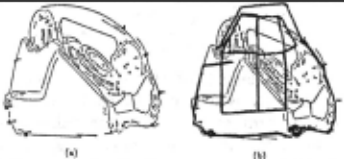
To evaluate the induced distortions, we compare the parameters of the adjustment transformations applied to the different model parts. The distortion is considered larger as the parameters of the transformation applied to its parts become more different.
A simple statistical analysis was applied to the param eters of the affine transformation extracted for the parts of the car class model. The scalar mean and the stan dard deviation of each of five parameters are computed for 11 parts (the linear coefficients of the affine transfr mation are replaced here by the more intuitive rotation and scalings). We compare the results obtained for two cases: the 'correct' case of fitting the car model to an actual car image, and fitting it to a telephone. The re sults are summarized in Table 1. An examination of the data reveals that a marked difference exists between the standard deviations in the two cases. The criterion used can be extended in several ways. For example, one may use the spatial variance of these parameters, i.e., giving a larger weight to the difference between the parameters oft wo parts if they are closer together. Nevertheless, the results seem promising, considering the simplicity of the computation that is performed.
| para- | car-car | car-telephone | ||
|---|---|---|---|---|
| meters | mean | std. dev. | mean | std. dev. |
| x-transl. | -10.51 | 12.36 | -6.10 | 54.20 |
| y-transl. | 7.36 | 3.15 | -40.12 | 20.64 |
| rotat10n | 0.04 | 0.11 | 0.12 | 0.25 |
| len.-scale | 0.91 | 0.21 | 1.17 | 0.53 |
| wid.-scale | 0.96 | 0.20 | 1.05 | 0.32 |
6 Summary
In this work we use the alignment approach to devise a scheme for classifying objects according to shape sim ilarity. While the complex classes such as "furniture" require more abstract, symbolic, information, it appears that basic level classification is often based on shape sim ilarity of the type used in this work.
The central theme of the method is that objects can be classified by applying compensating transformations to simple pictorial descriptions (essentially two dimen sional), used as the internal models. The classification scheme proceeds through the following three steps. First, a rough alignment process compensates for overall shift, scaling, and rotation. An important aspect of this stage is that it does not rely on global parameters that are sen sitive to occlusion. Second, an adjustment transforma tion is applied by matching features (corners) . Different parts (defined in the model only) may undergo differ ent transformations. Third, the quality of the match is evaluated based on the variability of the transformations applied to different parts. Despite the simplicity of the implemented procedures, results of applying this scheme support the notion that applying compensating trans formations to pictorial models can play a useful role in detecting shape similarities among object, and in object classification.
@inproceedings{ijcai1991p185,
  title     = {A Pictorial Approach to Object Classification},
  author    = {Shapira, Yerucham and Ullman, Shimon},
  booktitle = {Proceedings of the Twelfth International Joint Conference on
               Artificial Intelligence, {IJCAI-91}},
  publisher = {International Joint Conferences on Artificial Intelligence},
  editor    = {John Mylopoulos and Ray Reiter},
  pages     = {1257--1262},
  year      = {1991},
  month     = {8},
  note      = {Vision},
  url       = {https://ijcai.org/proceedings/1991/185},
}
TY - CPAPER TI - A Pictorial Approach to Object Classification AU - Shapira, Yerucham AU - Ullman, Shimon T2 - Proceedings of the Twelfth International Joint Conference on Artificial Intelligence, IJCAI-91 PB - International Joint Conferences on Artificial Intelligence PY - 1991 SP - 1257 EP - 1262 UR - https://ijcai.org/proceedings/1991/185 ER -Copied
Machine-readable versions of this paper, for tools and AI agents:





