
The Implementation of Expert, Knowledge-Based Systems
Proceedings of the Eleventh International Joint Conference on Artificial Intelligence. Real-time and High Performance. Pages 221-225.
© 1989 International Joint Conferences on Artificial Intelligence
Abstract
We discuss the problem of implementing an expert, knowledge-based system. In particular, we consider which predicates in an expert, knowledge-based system should be actually stored and which should be derived on demand. We present two solutions for unconstrained applications. When realistic ~onstraints are present it is shown that the problem IS r:w-complete. A sub-optimal algorithm is given whtch operates in polynomial time when the application is not heavily constrained.
- T.R. Addis "Designing Knowledge-Based Systems", Kogan-Page, 1985.
- [Debenham, 1985a] J.K. Debenham "Knowledge Base Design", Australian Computer Journal, 1985, Vol 17, No 1, pp 187-196.
- [Debenham, 1985b] J.K. Debenham "Knowledge Base Engineering", in proceedings of the Eighth Australian Computer Science Conference, Melbourne, 1985.
- [Debenham, 1987] J.K. Debenham "Expert Systems: an Information Processing Perspective", in "Applications of Expert Systems" (J.R. Quinlan, Ed), Addison-Wesley, 1987, pp 200-216.
- [Debenham, 1989] J.K. Debenham "Knowledge Systems Design", Prentice Hall, 1989.
- [Debenham and McGrath, 1982] J.K. Debenham and G.M. McGrath "The Description in Logic of Large Commercial Data Bases: A Methodology put to the test", in Proceedings of the Fifth Australian Computer Science Conference, pp. 12-21.
- [Even, 1979] S. Even "Graph Algorithms", Computer Science Press, 1979.
- [Gaines, 1987] B.R. Gaines "Foundations of knowledge engineering", in (M.A. Bramer, Ed.) "Research and Development in Expert Systems III", Cambridge University Press, 1987.
- [Garey et al., 1976] M.R. Garey, D.S. Johnson and L. Stockmeyer "Some simplified NP-complete graph problems.", Theoretical Computer Science, Vol 1, No 3, pp 237-267.
- [Martin, 1988] N. Martin "Software Engineering of Expert Systems", Addison Wesley, 1988.
- [Steels, 1987] L. Steels "Second Generation Expert Systems", in (M.A. Bramer, Ed.) "Research and Development in Expert Systems III", Cambridge University Press, 1987.
References were extracted automatically from the PDF and may contain errors.
Full text extracted automatically from the PDF; figures, tables and equations may differ. The PDF is the version of record.
1. Introduction
Many early expert systems have proved to be difficult to ?laintai~ [S~eels, 1987], as a result there is a growing mterest m ngorous design techniques for expert systems [Addis, 1985], [Martin, 1988], [Debenham, 1989]. The use of rigorous design techniques should mean that large expert ~ystems ~n be constructed and maintained effectively. Our mterest m the design of large, expert, knowledge-based systems was first reported in [Debenham and McGrath 1982]; ~ substantial development of that early work i~ reported m [Debenham, 1985a]. The effective construction and maintenance of large expert systems entails the solution to_ design problems which are not significant when dealing wtth smaller systems. One such design problem is considered here.
For the purpose of this discussion, we think of the kno~l~dge in an expert, knowledge-based system as conststmg of a collection of "rules", where a rule states how to deduc~ all that_ the!e is to know about one "predicate" from the mformallon m other predicates. For example, the rule "customers with steady income and regular expenditure are good credit risks otherwise they are poor credit risks" could be represented as a group of Hom clauses [Hogger 1984]: '
customer/risk( x, 'good') +
customer/income( x, 'steady'),
customer/expenditure( x, 'regular' )
customer/risk( x, 'poor' ) +
customer/income( x, 'variable' )
customer/risk( x, 'poor' ) +
customer/expenditure( x, 'erratic')
If these three clauses enable all the information in the predicate customer/risk to be deduced then they constitute a rul~. A rule can be represented by a "dependency diagram", whtch for the above example is shown in Figure 1.
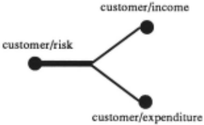
Figure 1
A dependency diagram for a rule shows that all the information in one predicate can be derived, using the rule, f~om the information in other predicates. The dependency d1agram shown in Figure 1 is for a rule expressed in Hom clauses. It should be clear that a dependency diagram can be constructed for rules expressed in any "if...then" formalism; thus the relevance of what follows is not restricted to systems expressed in logic. Note that a dependency diagram consists of one "thick arc" and one or more "thin arcs". The "thick ru:c" is connected to the head node which represents the predicate for which the information may be derived by the. rule. The "thin arcs" are connected to the body nodes which represent the remaining predicates in the rule.
An expert, knowledge-based system will contain a collection of rules which enables the information in the "query predicates" to be deduced from the information in the "update predicates"; where the update predicates are the predicat~s which are directly associated with the "input" mformatiOn, and the query predicates are the predicates which are directly associated with the identified query types of the expert system.
We assume that the collection of rules in an expert system is minimal in the sense that none of the rules can be disposed of. See [Debenham, 1985b] for a discussion on the selection of an optimal, minimal set of rules. Thus the rules in an expert system can be represented using a combined diagram which shows, on one diagram, the d~pendency diagrams for all of the rules. For example, FI_gure. 2. shows a combined diagram for an expert system wtth etght rules, three query predicates which are shown on the left, and four update predicates which are shown on the right.
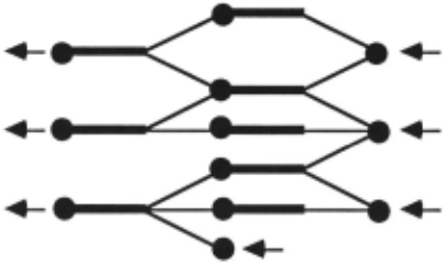
2. The Expert Systems Implementation Problem
The expert systems implementation problem may be defined informally as:
- to decide which of the predicates shown on the combined diagram should actually be stored so that
- the overall "system performance" is optimal.
We define the system performance of a storage allocation to be:
where Q is the set of query types and U is the set of update types. Tis a "cost function"; for example, T(q) is the "cost to service the query q"; and f is the "expected frequency function"; for example, f(q) is the "expected frequency of presentation of the query q".
For each query type q and update type u, let T(q) and T(u) respectively denote the maximum permissible cost of response. For each predicate r, let -r(r) denote the cost of storing r, and let C denote the total cost of the available storage. We are now in a position to give a formal statement of the expert systems implementation problem.
The Expert Systems Implementation Problem.
Given a combined diagram, given T(q) and T{u) for each qEQ and uEU , and given C, to choose a set of predicates R to be actually stored such that:
are satisfied and
is minimized.
In this discussion, it is necessary for us to restrict the form of recursion used in the rules. We will restrict ourselves here to "primary recursion" only. Denoting predicates by letters from the set {A,B,C,D,E}, a rule of the form:-
i.e. where a predicate name appears both as the head of the rule and within the body of the rule is called primary recursive. However this restriction does mean that exotic forms of recursion such as:
where the group of clauses with head A has C in its body and vice versa, would be excluded. In our experience, this does not impose a significant restriction in practical applications.
3. The Calculation of Minimal Storage
In this section we consider the calculation of storage allocations of least cost. We are interested in two particular forms of storage allocations, these are "irredundant storage allocations" and "divisions".
First we define what it means to say that one node in a combined diagram "depends" on another. Consider the three groups of Horn clauses:
the combined diagram for these three rules is shown in Figure 3.
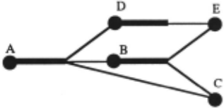
In a combined diagram, node X is said to depend on node Y if there is a path from Y to X in that diagram; where the direction of flow is that of logical · implication, i.e.from the body nodes to the head nodes. In the example shown in Figure 3, D depends onE, B depends onE and C, and A depends on all the other nodes in the diagram.
It is important to appreciate that the update predicates need not necessarily be stored in the high speed memory. The values of updates may be retained in auxiliary storage; these values may be required during subsequent update operations and may be required to regenerate the system in the event of a disaster. All that matters is:
- that all the values in all the stored predicates can be deduced from the values in the update predicates, and
- that all the values in all the query predicates can be deduced from the values in the stored predicates.
Thus we see that the set of stored predicates will, in a sense, divide the combined diagram into two portions. Thus, informally, we may think of a storage allocation as a subset of the set of nodes such that if the storage allocation were removed from the diagram then the resulting diagram would consist of two connected, possibly empty, components with one component containing no query nodes and the other component containing no update nodes. The idea is that the storage allocation represents those predicates which are actually stored; in other words, those nodes which are not in the storage allocation represent predicates which will be calculated when required. In the example shown in Figure 3, four different storage allocations show that the query predicate A may be deduced from any of the sets (B, C, D}, (D, E, C), (E, B, C) and (C, E}.
An irredundant storage allocation is a storage allocation with the property that if a node is removed from the storage allocation then the resulting set ceases to be a storage allocation. An irredundant storage allocation can be visualized as a minimal set of nodes which divides the graph into two portions. If a storage allocation is not irredundant, it is called a redundant storage allocation. In the example shown in Figure 3, two of the storage allocations quoted above are irredundant storage allocations; they are (B, C, D} and (C, E}. Note that for the storage allocation (B, C, D} the values of the update relation E cannot be recovered from (B, C, D} unless suitable, additional rules are available. In this case, if the values of E might be subsequently required then they would have to be retained in auxiliary storage.
A storage allocation is a division if it contains no two nodes which depend on each other. As we assume that the collection of rules in an expert system is minimal, if a selection of nodes from a combined diagram is a "division" then that selection will cease to be a storage allocation if any node is removed from the storage allocation; in other words, all divisions are irredundant storage allocations.
It is important to understand the difference between an irredundant storage allocation and a division. In the combined diagram shown in Figure 4 the storage allocation ( C, D, F } is an irredundant storage allocation because if any one of these three nodes were removed it would cease to be a storage allocation; but, ( C, D, F } is not a division because D depends on C. On the other hand, the storage allocation ( B, D, F } is a division.
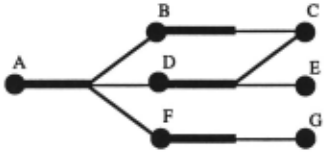
Flgure4
Non-division storage allocations are often desirable. However, divisions are of great practical significance because if a storage allocation contains one node that depends on another then the updates to the second node will also have to be reflected in the first
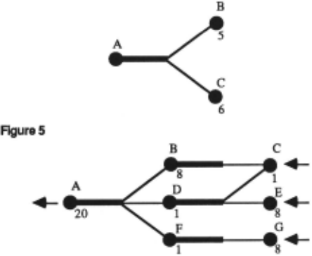
We now mark costs on the combined diagram. · These costs are intended to represent the cost of storing each predicate, and are written beside the node which represents the predicate to which the costs apply. For example, if the cost of storing predicate B was 5 and the cost of storing predicate C was 6, and B and C were in a dependency diagram with head predicate A then this would be denoted as shown on the diagram in Figure 5.
A storage ·allocation is called a minimal storage allocation if its cost is no greater than any other storage allocation. It is easy to show that minimal storage allocations are irredundant storage allocations but are not necessarily divisions. For example, consider the combined diagram as shown in Figure 6, the minimal storage allocation is the set ( C, D, F } which is irredundant but is not a division. We will now consider the calculation of both the division with least cost and the minimal storage allocation.
Problem 1.
To calculate the division with least cost
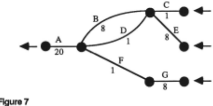
This problem can be solved by applying the (polynomial time) minimum cut algorithm to a modified version of the combined diagram. This modification is performed in two steps. First, all of the "thick" arcs in the combined diagram are "collapsed" to a point. Second, replace each node with a "pseudo-arc" marked with the node cost, and replace each "thin" arc with a "pseudo-node". The resulting diagram is called the division-dual diagram. The solution to Problem 1 may be found by applying the minimum cut algorithm to the division dual diagram. When the minimum cut has been calculated, the pseudo-arcs which lie on the minimum cut will correspond to the nodes in the division with least cost. See [Even, 1979], or any good book on algorithmic graph theory, for a description of the minimum cut algorithm.
For example consider the combined diagram shown in Figure 6; its division-dual diagram is as shown in Figure 7. From which we readily see that the division of least cost is ( C, E, F} or ( B, D, F } with a total cost of 10. Note that an arc in the division-dual diagram corresponds to a node in the original diagram, and vice versa.
We now consider the calculation of the minimal storage allocation.
Problem2.
To calculate the irredundant storage allocation with least cost; this is the minimal storage allocation.
This problem can be solved by applying the (polynomial time) minimum cut algorithm to a modified version of the combined diagram which is similar to that considered in the solution to Problem 1. This modification is performed in two steps. First, all of the "thick" arcs in the combined diagram are "collapsed" to a point. Second, replace each remaining "thin" arc with a "pseudo-node" and replace each node with a "pseudo-polygon" as follows:
- a node which is directly connected to one or two other nodes is represented by a pseudo-arc as in the solution to problem 1. This pseudo-arc is marked with the node cost
- a node which is directly connected to n other nodes, where n > 2 , is represented by an n-sided pseudo polygon with one comer of the polygon connected to the arc which is connected to each of the n nodes; the sides of the polygon are marked with the original node cost divided by two.
The resulting diagram is called the dual diagram. The solution to Problem 2 may be found by applying the minimum cut algorithm to this dual diagram. When the minimum cut has been calculated, the pseudo-polygons which lie on the cut will correspond to the nodes in the minimal storage allocation.
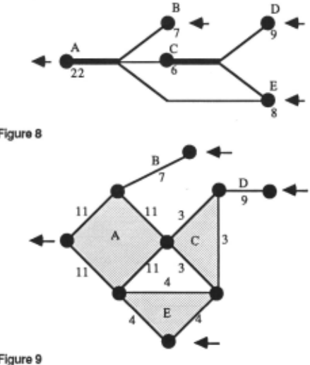
For example, the combined diagram shown in Figure 8 will generate the dual diagram shown in Figure 9. From which we see that the minimal storage allocation is { B, C, E ) with a cost of 21.
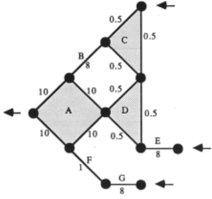
Also for example, consider the combined diagram shown in Figure 6; its dual diagram is as shown in Figure 10. From which we readily see that the minimum cut is { C, D, F ) with a total cost of 3.
4. Complexity of the Expert Systems Implementation Problem
The operational constraints and optimality criterion noted in the definition of the expert systems implementation problem together comprise a complex set of conflicting constraints.
THEOREM.
The expert systems implementation problem is NP complete.
Proof.
We will restrict and transform the expert systems implementation problem, and will show that this restriction and transformation is equivalent to the "Minimum Cut Into Bounded Sets" problem which is known to be NP-complete [Garey et al., 1976].
First assume that there is only one query type, q, and one update type, u. Then the expert systems implementation problem now reads:- Given a combined diagram, given constants T(q), T(u) and C, to choose a set of predicates R to be the storage allocation such that:
Second, adopt the following trivial measure for T, this measure defines T(q) to be the number of rules involved in servicing the query type q, and T(u) is just the number of rules involved in servicing the update type u. In other words, T(q) is the number of rules required to deduce the values of q from the values stored in R, T(u) is the number of rules required to deduce the values in R from the values in u. In addition we further restrict the problem to the special case when T(q) = T(u) = T. Then the expert systems implementation problem may be stated as:- Given a combined diagram, given constants T and C, to choose a set of predicates R to be the storage allocation such thatthe number of rules needed to deduce the values of q from the values in R is less than or equal to T
the number of rules needed to deduce the values of R from the values in u is less than or equal to T
are satisfied, and
We now transform the representation of this restriction of the expert systems implementation problem into the division dual diagram representation as discussed in the previous section. We will ignore the expression to be minimized, that is, we will just state the operational constraints. Recall that on the division dual diagram, predicates are denoted by arcs and rules are denoted by nodes. The expert systems implementation problem as restricted so far now reads:- Given a division dual diagram, constants T and C, to choose a partition of the set of nodes in the diagram, V, into two disjoint sets V 1 and V 2 such that the single query type q is directly connected to a node in V 1 and the single update type u is directly connected to a node in V 2 such that:
where lVI means "the number of elements in the set V", and R is the set of arcs with one node in V 1 and the other in V 2 ·
This final restriction and transformation of the expert systems implementation problem is precisely the "Minimum Cut into Bounded Sets" problem. This completes the proof.
We note from the proof of the theorem that what has actually been demonstrated is that the problem of finding .a solution to the expert systems implementation problem is NP-complete, never mind the problem of fmding an optimal solution. Thus we have:
Corollary.
Given a combined diagram, the problem of finding a solution which satisfies the operational constraints, but which is not necessarily optimal, to the expert systems implementation problem is NP-complete.
The "Minimum Cut into Bounded Sets" problem remains NP-complete even if l(r) = 1 (VrER) , and if T = lVI + 2 . Thus we note that the following restriction of the expert systems implementation problem is also NP complete. Given a dual diagram and constant C, to choose a partition of the nodes of the diagram into two disjoint sets V 1 and V 2 such that the single query node q is connected to a node in V 1 and the single update node u is connected to a node in V 2 such that:
In the special case when T = lVI it is clear that the problem of finding an admissible, but not necessarily optimal, solution to the expert systems implementation problem reduces to satisfying the single constraint
which can be solved in polynomial time by the minimum cut algorithm.
5. Sub-Optimal Storage Allocation
In the previous section we have seen that the expert systems implementation problem is NP-complete. However this does not imply that identifiable classes of sub-problems encountered in practice need.-necessarily be NP-complete. For example, the costs on the arcs in the combined diagram are often related to each other. Perhaps investigation of this observation, and others like it, might lead to some simplification.
We conclude our aiscussion with a sub-optimal algorithm for calculating the (hopefully) minimal storage allocation which satisfies query and update response constraints. This algorithm yields acceptable results in practice when the application is not heavily constrained. If the application has heavy query and update constraints then the algorithm may not find a solution.
The algorithm begins with the unconstrained minimal storage allocation as calculated in Problem 2. This minimal storage allocation is then "modified" to form other storage allocations which are all constrained to be irredundant.
In the statement of the following algorithm we will use the following notation. If, in a combined diagram, S is an irredundant storage allocation and n is a node not inS, then S t ( n) denotes the set of nodes obtained by adding n to S and removing from S any other nodes which, as a result of n being added, prevent S u ( n) from being irredundant.
Algorithm.
Find the minimal storage allocation. This may be done by employing our method given in Problem 2 on the dual diagram. If there is more than one such storage allocation then choose the storage allocation which violates fewest operational (i.e. query or update) constraints. (Recall that a storage allocation consists of a set of predicates; on the dual diagram this set will be represented by a set of polygons.) Represent this minimal storage allocation as a "cut" on the combined diagram. Then :-
begin( constraints)
let the storage allocation S be the minimal storage
allocation as described above while there are query nodes with unsatisfied operational constraints do let pQ be the nodes in S on which query nodes with unsatisfied operational constraints depend let pGB be the set of rules with at least one body node in pQ let pH be { n : n ~ S and n is the head node of a rule in pGB} if there is a node n in pH such that S t { n} satisfies a presently unsatisfied query constraint then let N be n else let N be the node with the property that the storage allocation S t {N} has the lowest query cost of all the storage allocations { S t {n} : n E pH } let S be S t {N} endwhile [By this stage S will be an irredundant storage allocation which satisfies all the query operational constraints.] while there are update nodes with unsatisfied o~rational constraints do let P be the nodes in S which depend on one or more update nodes with unsatisfied operational constraints let pGH be the set of rules with head node in pU let pB be { n: n ~ S, n is a body node of a rule in pG H and S t { n} violates no query constraints} if pB = ¢ then halt("unsuccessful") else if there is a node n in P 8 such that S t ( n} satisfies a presently unsatisfied update constraint then let N be n else let N be the node with the property that the storage allocation S t (N} has the lowest update cost of all the storage allocations { S t ( n} : n E P 8 } let S be S t (N} endwhile end [By this stage S will be an irredundant storage allocation which satisfies all the query and update operational constraints but may not give rise to optimal system performance.] begin( optimize) let pGH be the set of rules with head node in S let pB be { n: n ~ S, n is a body node of a rule in pGH and S t (n} violates no query and update constraints } let pGB be the set of rules with .at least one body node inS let pH be ( n : n ~ S, n is the head node of a rule in P 08 and S t ( n} violates no query or update constraints } if pB u pH = ¢ then balt("successful") else let P 0 be ( n: n E P 8 u pH such that the system performance of S t {n} is lower than the system performance of S }
tDI
It can be shown that if the algorithm halts signalling "successful" then it will halt in polynomial time.
6. Summary
We have discussed several factors which will influence the choice of a storage allocation for an expert system. Two solutions have been proposed for un-constrained applications. It has been argued that when realistic constraints are present, the determination of the optimal storage allocation is NP-complete. A sub-optimal algorithm has been given which operates in polynomial time when the application is not heavily constrained.
@inproceedings{ijcai1989p35,
  title     = {The Implementation of Expert, Knowledge-Based Systems},
  author    = {Debenham, John K.},
  booktitle = {Proceedings of the Eleventh International Joint Conference on
               Artificial Intelligence, {IJCAI-89}},
  publisher = {International Joint Conferences on Artificial Intelligence},
  editor    = {N. S. Sridharan},
  pages     = {221--225},
  year      = {1989},
  month     = {8},
  note      = {Real-time and High Performance},
  url       = {https://ijcai.org/proceedings/1989/35},
}
TY - CPAPER TI - The Implementation of Expert, Knowledge-Based Systems AU - Debenham, John K. T2 - Proceedings of the Eleventh International Joint Conference on Artificial Intelligence, IJCAI-89 PB - International Joint Conferences on Artificial Intelligence PY - 1989 SP - 221 EP - 225 UR - https://ijcai.org/proceedings/1989/35 ER -Copied
Machine-readable versions of this paper, for tools and AI agents:





