
Creature Design with the Subsumption Architecture
Proceedings of the Tenth International Joint Conference on Artificial Intelligence. Robotics. Pages 1124-1125.
© 1987 International Joint Conferences on Artificial Intelligence
Abstract
The mobile robot group at MIT has been building robots using the subsumption architecture. This methodology decomposes a control system into a set of loosely coupled task achieving behaviors. In this paper we show how the constraints inherent in this approach naturally lead to a very simple computational design. To demonstrate its effectiveness we have built a new, small, fast robot based on these ideas. In this paper we discuss the performance of this robot and the theory behind its construction.
- Ronald C. Arkin: "Motor Schema Based Nav- igation for a Mobile Robot"; submitted to the IEEE Conference on Robotics and Automation, 1987.
- Rodney A. Brooks: "A Robust Layered Control System for a Mobile Robot" ; IEEE Journal of Robotics and Automation, RA-2, No 1. , April1986 .
- and Connell86] Rodney A. Brooks and Jonathan H. Connell: "Asynchronous Distributed Control System for a Mobile Robot"; SPIE Proceedings, Vol. 727, Oc- tober 1986, 77-84.
- Brooks, Connell, and Flynn 86]
- Rodney A. Brooks, Jonathan H. Connell, and Anita M. Flynn: "A Mo- bile Robot with Onboard Parallel Processor and Large Workspace Arm"; Proceedings of AAA/-86, 1096-1110.
- Kenneth Dale Forbus: "Qualitative Process Theory''; MIT AI Lab Technical Report 789, June 1984.
- Kaebling Leslie Pack Kaebling: "An Architecture for Intelligent Reactive Systems" ; SRI International and Stanford University, April 1986.
- Minsky Marvin Minsky: The Society of Mind; Simon and Schuster, New York, 1987.
- David W. Payton: "An Architecture for Reflex- ive Autonomous Vehicle Control"; IEEE Robotics and Automation Conference, San Francisco, April 1986.
References were extracted automatically from the PDF and may contain errors.
Full text extracted automatically from the PDF; figures, tables and equations may differ. The PDF is the version of record.
1. Introduction
The mobile robot group at MIT has been investigating Brooks's 5Ub5umption architecture [Brooks 86). This archi tecture advocates decomposing control systems into "task achieving behaviors" where each behavior is a complete con trol system going from sensory inputs to motor outputs. Several other researchers [Kaebling 86, Payton 86, Arkin 86, Minsky 87) have proposed similar systems. The unique aspect of the subsumption architecture is that it allows a control system to evolve by accretion of new "levels" . Once a behavior is debugged it is never changed; more sophisti cated control systems are built around it. This is possible because of a simple, extensible arbitration scheme.
The control system for the new robot described here is cast in the subsumption architecture framework and closely resembles that of our earlier robots [Brooks and Connell 86). The difference is that, instead of running on a lisp machine or a special parallel processor, it has been hand compiled down to a couple hundred gates. We were able to accomplish this because, rather than trying to model an ever-changing world and then using this model to plan a course of action, each be havior simply tells what action to take in a specific situation. The subconscious reflex-like nature of this process allows us to eliminate complex intermediate representations and thus vastly simplifies the internal data-paths of a behavior.
Furthermore, not only do we use the world as its own model, we also use it as a communication medium between behaviors. Indexing off the state of the real world is more reliable than predicting what will happen as the result of a particular action. It also allows us to coordinate many behaviors without incurring the high cost of tight internal along the resultant vector. This behavior has no notion of what an obstacle is, it simply knows how to drive the car given certain sensor patterns.
Support for this work was provided by the Advanced Research Projects Agency under Office of Naval Research contracts N00014-80-C-0505 and N00014-82-K-0334.
A second behavior pays special attention to the front depth-finders to make sure the robot is not chased into a wall: when something gets too close, this behavior halts all forward motion. Note that we didn't try to build a unitary collison avoidance mechanism, instead we built a fairly reli able behavior and then patched it up in certain cases. Note, also, that there is no communication between the two behav iors: the collide behavior only knows the runaway behavior is failing when it detects a certain configuration in the world.
4. Exploring the Environment
The simplest way to make Tom explore is to give him an urge to go forward. We do this by adding another forward pointing vector to the result of the potential field calculation. By adding a constant force we make the robot go straight forward in an open space but veer away when it detects an obstacle. Like Simon's ant, we trust the complexity of the environment to yield an interesting path.
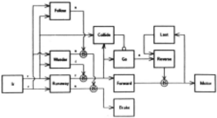
Figure 2 shows the complete control system for Tom. Here, the exploratory behavior is wired up somewhat dif ferently than in the control systems we have used in the past. With previous robots we broke the level zero runaway behavior into a potential summing module and a separate thresholding module. This allowed us to use the result of the force computation at higher levels. Unfortunately, with one bit data paths, Tom boils the potential field calculation down to plus, minus, and zero. Since we only know the sign, not the magnitude, the Wander module must recompute the force from the IRs rather than just adding its vector to the previous result.
5. The Social Robot
Tom's most sophisticated behavior is seeking a specific target . In the past we have had our robots find such things as corridors and doorways. However, due to the crude sensors on Tom, he is incapable of either of these behaviors. Instead, we have built a second robot, Jerry, indentical to Tom. To encourage interaction, Tom's seeking behavior is to find and follow Jerry.
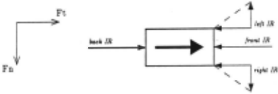
There were two observations that guided our choice of a following algorithm. The first was that the target being pur sued moved very rapidly. Thus, if the sensors don't see the target , the pursuer should continue to go straight forward in an attempt to catch up. The other observation was that the target usually moved forward only, it seldom reversed. This means the pursuer should never back up - given the speed of the target, by the time the it actually started to go forward again the target would be hopelessly far ahead.
The algorithm Tom uses is shown in Figure 3. We keep the strong forward vector from level one, represented by the large arrow in the middle, but we now make the side IRs attractive normal to the direction of travel (they remain repulsive in the tangential direction). This is sufficient to cause the car to turn toward obstacles rather than away from them. It does this, however, without having any idea that there is a "thing" that it is chasing. Note, also, that because the Collide behavior is still operative, the car will stop before actually hitting the object it is following.
An important part of multi-level systems like this one is determining when to switch from one behavior to another . In this case, the transition from the level one exploratory behavior to this level two seeking behavior is keyed to the activity of the side two IRs. When the robot is in a com plex portion of the environment, constantly veering around obstacles, the side IRs are active a large portion of the time. Conversely, when these sensors become inactive it usually means the robot is in a large open space. In such a case the vehicle switches into follow mode, actively seeking ob stacles. Note, however, that if the object being followed ever stops, the side IRs come on and stay on causing the robot to eventually revert to the wander mode.
6. Implementation
The interesting part is how a PAL can be made to per form complex calculations such as the polar coordinate vec tor summation required by the potential field algorithm. Let I, , lb. I, , and Ir be the forward, backward , left, and right proximity sensors respectively. These variables take a value of one or zero depending on whether the associated sensor sees an obstacle or not. We can now write an expression for the forward-backward force, F1:
To put this on the PAL we break it down into cases, much like is done in Qualitive Process theory (Forbus 84]. The robot should go forward when F1 > 0, backwards when F1 < 0, and stay still when F1 = 0. We can see that the only case in which F1 is postive is when the back IR senses an obstacle and, at most, one of the side IRs is active. We can encode this as a boolean expression for when to go forward. Using similar arguments for the other two cases we come up with the following expressions:
a 1 is true when the robot should be going forward and a6 is true when the robot should retreat. Notice that these expressions are in exactly the right form for the PAL: an OR of ANDs.
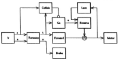
The runaway behavior described by these expressions works fairly well except that the robot can't stop quickly. One way to decrease the stopping distance is to run the motor in reverse for a little while. As can be seen in figure 4, this active braking scheme is built on top of the existing control system. The Go module determines when the robot should be moving and reports this on its output, A:
When the Reverse module sees the A line go low it knows that the robot is supposed to stop. It uses the output of the Last module to determine which direction to run the motor. D 1 means the car was advancing and so the motor should be run in reverse, while Db means the car was going backward so the motor should be run forward to slow it down. The command from the Reverse module suppruses the output of the. Forward module. The suppresion is implemented by using the allowed motion signal, A, to select which module gets control:
We now have a control system that causes the robot to run away from attackers. Unfortunately, it occasionally causes collisions which could have been avoided. Consider the case where all the proximity sensors detect obstacles. According to the expression for a. , the robot should go backwards even though it knows there is something in the way. We remedy this by adding a special collision avoidance behavior. As shown in Figure 4, we do this by adding a new module, Collide, which inhibits the output of the Go mod ule. The Collide module looks at the commanded direction and the central IRs to decide whether it is safe for the robot to move. The actual inhibition is performed by ANDing the allowed motion signal, A, with the invert of the halt case.
The next two layers of the control system are imple mented in a similar fashion on the same PAL.
7. Conclusions
In this paper we have described Tom, a working robot based on the subsumption architecture, and shown how it operates with a minimal amount of computing power. The simplicity of this design has allowed us to create several iden tical vehicles and let us start to explore the ways in which communities of creatures interact.
Acknowledgements
Thanks to Rod Brooks and the people in the mobile robot group, especially Wendy Wang and Peter Ning.
@inproceedings{ijcai1987p227,
  title     = {Creature Design with the Subsumption Architecture},
  author    = {Connell, Jonathan},
  booktitle = {Proceedings of the Tenth International Joint Conference on
               Artificial Intelligence, {IJCAI-87}},
  publisher = {International Joint Conferences on Artificial Intelligence},
  editor    = {John McDermott},
  pages     = {1124--1125},
  year      = {1987},
  note      = {Robotics},
  url       = {https://ijcai.org/proceedings/1987/227},
}
TY - CPAPER TI - Creature Design with the Subsumption Architecture AU - Connell, Jonathan T2 - Proceedings of the Tenth International Joint Conference on Artificial Intelligence, IJCAI-87 PB - International Joint Conferences on Artificial Intelligence PY - 1987 SP - 1124 EP - 1125 UR - https://ijcai.org/proceedings/1987/227 ER -Copied
Machine-readable versions of this paper, for tools and AI agents:





