
Graphical Deep Knowledge for Intelligent Machine Drafting
Proceedings of the Tenth International Joint Conference on Artificial Intelligence. Knowledge Representation. Pages 545-550.
© 1987 International Joint Conferences on Artificial Intelligence
Abstract
T he problem of Intelligent Machine Drafting is presented, a nd a de sc ription of an ex is ting implementation as part of a graphical generator functi on is given. The concept of Graphical Deep Knowledge is defined as a representational basis for Intelligent Machine Drafting problems as well as for physical object displays. A (partial) task domain analysis for Graphical Deep Knowledge is presented. Primitives that are necessary to deal with a world of 2-D forms and colors are introduced. Among them a re primitives for describing forms, positions, parts, attributes, sub-assemblies, and an abstraction hierarchy. The use of the "linearity principle" for knowledge structure derivation fr om natural language utterances is shown.
- D. C. Brown and B. Chandrasekaran, "Design Consideration for Picture Production in a Natural Language Graphics Sys- tem," Computer Graphics 1S(2) pp. 174-207 (July 1981).
- Stuart C. Shapiro, Sargur N. Srihari, Ming-Ruey Taie, and James Geller, "VMES: A Network Based Versatile Mainte- nance Expert System," Proc. of 1st Interrultional Confer- ence on Applications of AI to Engineering Problems, pp. 925-936 Springer Verlag, (April 1986).
- Stuart C. Shapiro, 'The SNePS Semantic Network Processing System," pp. 179-203 in Associative Networks: The Representation and use of Knowledge by Computers, ed.
- Nicholas V. Findler,Academic Press, New York (1979).
- Stuart C. Shapiro, "Using Non-Standard Connectives and Quantifiers for Representing Deduction Rules in a Semantic Network," Presented in Tokyo at: Current Aspects of AI Research, (Aug. 27-28, 1979).
- Stuart C. Shapiro and James Geller, "Artificial Intelligence and Automated Design," 1986 SUNY Buffalo Symposium on CAD: The ComputabiUty of Design, SUNY at Buffalo, (Dec 6-7, 1986).
- Stuart C. Shapiro and William J. Rapaport, "SNePS Con- sidered as a Fully Intensional Propositional Semantic Net- work," Proceedings of the Fifth National Conference on Artificial InteUigence, pp. 278-283 (1986).
- Hajimu Mori, Fujita Tomoyuk.i, Masahiro Annaka, Satoshi Goto, and Tatsuo Ohtsuk.i, "Advanced Interactive Layout Design System for Printed Wiring Boards," pp. 495-523 in Hardware and Software Concepts in V LSI, ed. Guy Rabat,Van Nostrand Reinhold, New York (1983).
- !sao Shirakawa, "Routing High Density Printed Wiring Boards," pp. 452-479 in Hardware and Software C('rtcepts in V LSI, ed. Guy Rabat, Van Nostrand Reinhold , i'.e\\ York ( 1983).
- Helmut Jansen, Erhard Nullmeier, and Karl-Heinz Roediger, "Handsketching as a Human Factor Aspect in Graphical Interaction," Computers and Graphics 9(3) pp. 195-210 (1985).
- M. C. Maguire, "A Review of Human Factors Guidelines and Techniques for the Design of Graphical Human-Computer Interfaces," Computas and Graphics 9(3)pp. 221 -235 (1985).
- Michael Hussman and Peter Schefe, "The Design of SWYSS, a Dialgue System for Scene Anal ysis," pp. 143-201 in Natural Language Communication with Pictorial Informa- tion Systems, ed. Leonard Bole, (1984).
- Frank Zydbel, Noton R. Greenfeld, Martin D. Yonke, and Jeff Gibbons, "An Information Representation System," Proceedings of the Seventh International Joint Confer- ence on Artificial Intelligence, pp. 978-984 (1981).
- Mark Friedell, "Automatic Synthesis of Graphical Object Descriptions," Computer Graphics 18(3) pp. 53-62 (1984).
- Stephen M. Kosslyn and Steven P. Shwartz, "A Simulation of Visual Imagery," Cognitive Science 1 pp. 265-295 ( 1977).
- Stephen Michael Kosslyn, Image and Mind, Harvard University Press, Cambridge MA (1980).
- Zenon W. Pylyshyn, ''The Imagery Debate: Analogue Media versus Tacit Knowledge," Psychological Review 88( I) pp. 16-45 ( 1980.
- Zenon W . Pyl ysh yn, Computation and Cognition , \1IT Press, Cambridge MA (1984).
- Lofti A. Zadeh, "Commonsense Knowledge representation Based on Fuzzy Logic," Computer, pp. 61 -65 (Oct. 83).
- Stuart C. Shapiro and The SNePS Implementation Group, "SNePS User's Manual," SNeRG Bibliography #31, SU NY at Buffalo (Sept. 1983).
- Mary Angela Papalaskaris and Lenhart Schubert, "Parts Inference: Closed and Semi-Closed Partitioning Graphs," Proceedings of the Seventh lnterrultional Joint Confer- ence on Artificial Intelligence, pp. 304-309 (1981). IJCAI
- Fanya S. Montalvo, "Diagram Understanding: The Intersec- tion of Computer Vision and Graphics," AI Memo 873, MIT (Nov. 1985).
References were extracted automatically from the PDF and may contain errors.
Full text extracted automatically from the PDF; figures, tables and equations may differ. The PDF is the version of record.
1. Concrete and Fuzzy Absolute P01itions
m5( object dl abspos m6( x 100 y 200) modality function) (5)
(5) describes an absolute position of d I. The position is given by the substructure m6 which contains actual coordinate values.
The pseudo predicate m6 has to be read as a structured indivi dual, not as a proposition [6]. The implicit assumption of this representation is that coordinates are given in pixels of a graphics display device and are "relative to the screen", and therefore called absolute.
When people give a description of a picture, they typically do not use coordinate values but rather talk about objects in the center, at the top, or at the left of the screen. According to the linearity principle it is therefore necessary to represent these "fuzzy" absolute positions. (6) shows an example of a fuzzy absolute position.
Currently the exact meaning of the fuzzy terms is still under investigation. We have done a psychological pilot study with 20 subjects to find out what people think "leftness" means, which has not yet been totally evaluated. Fuzzy absolute positions used in this experiment are top, bottom, left, right, center, upper left corner, upper right corner, lower left corner, and lower right corner. The term "fuzzy" is not related to Zadeh's fuzzy logic [18).
2. Relative Positions
Propositions about relative positions can be divided into different groups, according to a number of criteria. The first dis tinction is between numeric positions (what we refer to as "con crete" positions) and fuzzy positions. For numeric positions there are at least three different ways to interpret coordinate values. Values can be given in pixels, or they can be multiples of the sizes of either the object or the reference object involved.
The reference object might be given explicitly or implicitly. In the second case there must be a "super-part" of the object which will be used as the reference object. Finally it might be the case that a relative position is inherited from a class of objects. Many of the given representational possibilities can be combined with each other.
- Fuzzy Relative Positions--As for fuzzy absolute positions the analysis of the semantics of fuzzy relative positions is still under way and based on experimental data.
(7) describes the proposition that d3 is left of dl.
Unfortunately there are a number of fuzzy relative posi tion descriptions which do not rely on binary relations. A representation for "between", which has two reference objects is shown in (8). More difficult are "on-one-line", "together", and "farming-a -circle".
- Concrete Relative Positions--We will begin this section with an example for a relative position measured in pixel coordinates. Fig. 3 shows as example a multiplier. The little black boxes in the picture are ports (sic!) of the multiplier and have their own forms.
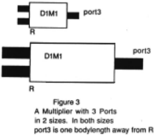
- describes the relative position of port3 as being 24 to the right of DtMt, and 4 above it. Distances refer to the reference point R. If the relative position of a part of an object is given in pixel coordinates then a problem with scaling results: not only objects have to be scaled, but also relative positions. This is unsatifying because it does not express the fundamental invariance of the position of the sub-part to its super-part. Fortunately it is possi ble to represent the relation between an object and its sub-parts preserving the conceptual positional invariance by using "body coordinates". These coordinates represent a relative position as multiples of the size of the relevant object.
(10) shows the same relative position as (9), however assuming that object port3 has a length of 8 pixels and a width of 4 pixels. The relative position "3", is a multiple of the size of port3. The length and width of an object are the length and width of the smallest surrounding rectangle of it which has lines parallel to the coordinate axes ("extent" ).
Intuitively, the representation expresses the fact that a big man has his arms far away from his neck, and a small child has its arms near to the neck, but the ratio of the distance and the size of the person should be approximately a constant.
Usually there will be a number of objects given with rela tive positions to the same reference object. This makes it desir able to specify relative positions in body coordinates of the refer ence object, shortly called reference object coordinates (denoted by the arcs brx and bry ).
- (It) can be interpreted in the same way as (tO), except that this time the factors (after "brx", "bry") apply to the size of the refer ence object, which is assumed to be 24 pixels long and 12 pixels high.
- Explicit versus Implicit Reference Objects-- In all cases so far the reference object of a relative position state ment was given with a rei-to arc. In the circuit board mainte nance domain a flat part hierarchy is used. There is one major object, the board, which has many different parts which should reasonably be placed relative to this main object. It would be redundant to assert the reference object for all the parts, and therefore a default assumption is practical.
m16(object d5 relpos m17(x 100 y-20)
modality function)
m18( object d6 sub-parts d5 modality function)
(12)
(13)
(13) shows a part assertion, a descriptive tool that will be reviewed later on. Because of ( 13) the relative position asserted by (12) will be interpreted as being relative to d6.
Combinations of the representational constructs introduced are in general possible. For instance an implicit reference object may be used with all types of relative coordinates, including fuzzy ones (14, 15).
m20( object d8 sub-parts d7 modality function) (15)
d. Inherited Relative Positions--If one adder has its first port at half a body length from its reference point, then this will presumably hold true for all the adders in the system, and one would not want to assert this over and over again. A solu tion to this problem is to make the relative position itself inherit able. This option is exemplified by the following set of proposi tions. The relative position is given in reference object coordi nates and inherited through an intermediate class "half-adder".
| m21( object d9 type half-adder modality function) | (16) |
| m22( object d10 sub-parts d9 modality function) | (17) |
| m23( sub-class half-adder class adder modality function) | (18) |
| m24( object d10 form xadd modality function) | (19) |
| m25( class adder relpos m26( brx 2 bry .5) modality function) | (20) |
(16), (18), and (20) specify the relative position of d9 which is inherited from the class "adder"; ( 17) specifies the refer ence object d10 by force of its super-part relationship to d9. (19) is necessary to permit the derivation of the size of d 10 which in turn is necessary for the computation of reference object coordi nates.
3. Logical Reasoning with Fuzzy Positions
The following structure is a SNePS rule that expresses the fact that "if one object is left of another object, then the other object must be right of the first object and vice versa". For a detailed explanation of the structure of SNePS rules, see [19]
If the knowledge base contains the absolute position of B and the fuzzy position of B relative to A but no positional information about A itself, then A's fuzzy position can be derived with rule (21) or a variation of it.
D. Parts. Cluaten. and Aaemblies
Part hierarchies are a commonly used construct in AI [20! Our research has indicated that a part hierarchy alone is not sufficient for g,-aphical deep knowledge representations. We have added two other types of part-like hierarchies, called assemblies and clusters.
The display of a complicated object with several levels of parts might be impossible on a limited resolution display device. A natural way to limit the complexity of such a display task is to limit the number of levels of the hierarchy that are actually displayed. This is a very elegant solution because it does not require the introduction of any new representational construct.
(17) showed our representation of a simple part relation. An object can of course have more than one part. The ubiquitous modality attains a special importance for part hierarchies. Cir cuits like AND gates, OR gates etc. are displayed as single objects in a logical diagram. In real hardware there are usually four binary AND gates in a single chip. These four gates might be parts of different logical units. However, in a physical represen tation all four of them must be parts of the same integrated cir cuit.
1. A11emblies
Work. on the maintenance part of the VMES project has led to the realization that certain objects should never be displayed without their parts. For instance, a port is a part of a multiplier, but a multiplier should never be displayed without its ports. Sub-assemblies are therefore objects that have a real part-whole relation to a specific object and which are supposed to be displayed whenever the object they are part of is displayed.
The representation of sub-assemblies is similar to part whole relations, except that the arc "sub-assems" is used instead of "sub-parts".
m30( object dto sub-assems d9 modality fUnction)
(22)
2. Clusters
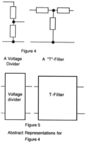
Printed circuit boards sometimes show groups of objects that stand in a logical relation to each other, comparable to a part-whole relation. Nevertheless they are neither sub-parts nor sub-assemblies. Sub-parts and sub-assemblies have a main object that is itself displayable, i.e. that has a form. However, a group ing of components might consist of objects of the same size and importance, none of which deserves the status of main object. Fig. 4 shows a voltage divider and a T filter which are typical examples of such circuits.
A grouping which exists only as an abstraction is called a cluster. If one combines the concept of cluster with the concept of level a dilemma emerges. Either the abstract object is left out of the hierarchy (which is undesirable, because anything that seems natural to a person should be directly representable in the network (LP!)), or the abstract object is put in the hierarchy and the objects of the cluster are made its parts. But now the idea of creating simplified displays by limiting the number of levels displayed does not work any more, because the abstract object is not displayable in the same sense as real objects are. Moreover if one is willing to give an abstract object a symbolic form, then both the symbolic form as well as the cluster elements would be displayed if one wants to see all the levels of the part hierarchy. This would complicate the display unnecessary.
Our answer to this problem is to create an additional hierar chy which stands somewhere in between a part hierarchy and an abstraction hierarchy. If A is an object (without form) which has sub-clusters n, C, and D then A will be displayed only by displaying D, C, and D. However if a partial display is enforced in a way that would exclude the level of B, C, and D from showing, A will be displayed symbolically by a box, akin to the display format in block diagrams. Fig. 5 shows the new display format for Fig. 4. The network representation of a sub-duster is shown by (23).
m31( 0bject d10 sub-clusters d9 modality function)
(23)
E. Attributes and Attribute Mappine-s
One important factor in designing a system based on graphi cal deep knowledge is a clear separation between icons and the objects that are represented by these icons, an observation that has been made by others also [21L This separation forces one to distinguish between attributes of objects and attributes of pic tures. A typical example of an attribute of a picture is bUnking. On the other hand, faultiness is an attribute of a component, not of the picture of a component. Attributes like faultiness cannot be displayed directly and therefore have to be symbolized with pictorial attributes.
Attributes are represented by the name of an attribute-class with 0 to 3 positions for attribute values. The following exam ples show an attribute with no attribute-value (24), an attribute with one position containing the value "faulty" (25), and an attribute with two positions containing the values "left" and "90" (26). No need for any attributes with more than three posi tions for attribute-values has arisen yet.
| m32( object d 1 attr m33( atrb-cls new modality function)) | (24) |
| m34( object d 1 attr m35( atrb-cls state | (25) |
| atrb faulty modality function) m36( object d2 attr m37( atrb-cls rotated | (26) |
| atrbl left atrb2 90 modality function) |
The attribute statements (24) - (26) apply to objects as opposed to pictures.
Attribute classes are linked to functionals that can be applied to form functions. Such a functional is called a modi.fter function. (26) asserts that d2 has the attribute-class "rotated" with two values "left" and "90" (degrees), which requires a change to its form before it can be displayed correctly. Therefore a modifier function that rotates forms is bound to this attribute class and the form of d2 is passed to it as first argument. The attribute values (marked by the arcs atrb, atrbl, atrb2 and possi bly atrb3) are passed in correct order as additional arguments to the modifier function.
The binding of an attribute-class to a modifier function is as.~erted in the knowledge hase. This makes it amenable to easy change hy the user. Utterances like have led to this representational decision (linearity principle!). In (27b) the complete mapping necessary for (27a) is given.
m38( attr state mod-func color modality function vall m39( expressed faulty expressed-by red) vall m40( expressed good expressed-by blue)) (27b)It binds the attribute-class "state" to the modifier-function "color". The two sub-structures at the end of the vall arcs show value mappings between object attributes and picture attributes. The object attribute of faulty state is represented by the picture attri bute of red color. vall corresponds to atrbl and specifies value mappings that apply to the first attribute position.
Sometimes one encounters numerical attribute values as in (26). Representing a mapping between two large lists of numbers would be unwieldy to impossible. Luckily in many practical cases the relation between the attribute value of a picture and the attribute value of the corresponding object is an identity function. This case is taken care of by using the attribute value of the object if there is no explicit mapping from object value to picture value. This also can take care of a mapping that is the identity function except for a few singularities.
If a more complicated function is necessary to transform from object attribute-value to picture attribute-value then the mapping function has to be integrated in the attribute functional itself.
The method used to associate an actual function with an attribute-class is identical to the method used for form functions. The node specifying a modifier-function is at the same time the name of a LISP function.
An important finding of our work has been that there is inheritance along part hierarchies, something we have not yet seen in the literature. For instance, if an object is represented with an attribute like "scaled", then one would want all its parts to inherit this attribute. Even more interesting is the fact that this inheritance does not apply to all attributes and depends on the attribute-class itself. If one asserts, for instance, the faulti ness of an object then it would defeat the whole purpose of a maintenance system to have all its parts inherit faultiness.
Given that one can easily express a fact like "scaling is inheritable", one should also (linearity principle!) have a correspondingly simple representation in the network which is exactly what has been implemented.
m41( inheritable size)
If (28) is part of the current knowledge base then the attribute class "size" will apply to the parts of all objects for which the size attribute has been asserted.
IV IMPLEMENTA TIONAL STATE
TINA is going through its fourth cycle of implementation which is done in Franz I.ISP on top of SNePS. All of tl;le shown knowledge structures (and more) are representable and retriev able from the network knowledge base, and most of them are interpreted in a way consistent with the descriptive semantics given in this paper. An older version of "TINA" has been applied to a real circuit board used for telecommunication purposes (PCM board). The IMD system described has been used for the Adder Multiplier only.
V CONCLUSIONS
The problem of Intelligent Machine Drafting has been intro duced, and it was argued that it is a theoretically interesting AI problem which is sufficiently different from other CAD tech niques to deserve separate investigation. The class A *M* has been defined informally, and a few additional restrictions of the current IMD implementation for objects of this class have been given. The definition of Graphical Deep Knowledge and a (par tial) task domain analysis of this area have been presented. A number of representational primitives have been introduced by way of example. These primitives comprise structures for representing knowledge about forms, concrete and fuzzy posi tions, and attributes. Positions have been differentiated into abso lute and relative positions with explicit and implicit reference objects. Pixel based coordinates, body coordinates and reference object coordinates have been introduced. Part hierarchies have been discriminated into real part hierarchies, sub-assemblies, and abstraction-hierarchy like clusters of objects. The derivation of some of these structures based on the "linearity principle" has been demonstrated, by presenting examples for motivating natural language utterances. A generator function which creates
graphical representations from a knowledge base containing the indicated structures has been implemented. ·
@inproceedings{ijcai1987p109,
  title     = {Graphical Deep Knowledge for Intelligent Machine Drafting},
  author    = {Geller, James and Shapiro, Stuart C.},
  booktitle = {Proceedings of the Tenth International Joint Conference on
               Artificial Intelligence, {IJCAI-87}},
  publisher = {International Joint Conferences on Artificial Intelligence},
  editor    = {John McDermott},
  pages     = {545--550},
  year      = {1987},
  note      = {Knowledge Representation},
  url       = {https://ijcai.org/proceedings/1987/109},
}
TY - CPAPER TI - Graphical Deep Knowledge for Intelligent Machine Drafting AU - Geller, James AU - Shapiro, Stuart C. T2 - Proceedings of the Tenth International Joint Conference on Artificial Intelligence, IJCAI-87 PB - International Joint Conferences on Artificial Intelligence PY - 1987 SP - 545 EP - 550 UR - https://ijcai.org/proceedings/1987/109 ER -Copied
Machine-readable versions of this paper, for tools and AI agents:





