
Compiling Design Plans from Descriptions of Artifacts and Problem Solving Heuristics
Proceedings of the Tenth International Joint Conference on Artificial Intelligence. Knowledge Representation. Pages 552-557.
© 1987 International Joint Conferences on Artificial Intelligence
Abstract
An analysis of the design plans in the Pride expert system shows that they integrate knowledge about structure and functionality of artifacts as well as problem-solving heuristics. A method is presented by which such plans can be automatically generated by compiling knowledge about artifacts, problem solving heuristics, and characteristics of specific problems. Knowledge compilation allows the creation of plans tailored to particular problems and offers potential benefits in maintaining a knowledge base, in reusing the same knowledge for different purposes, and in providing a framework for more systematic knowledge acquisition.
- Brown, D. C. and B. Chandrasekaran "Knowledge and Control for a Mechanical Design Expert System ." Computer, July 1986.
- Chandrasekaran, B. and S. Mittal "Deep versus compiled knowledge structures for diagnostic problem solving." In Proc. AAAI-82, August, 1982.
- deKieer, J. and J.S.Brown "A Qualitative Physics Based on Confluences." In Qualitative Reasoning about Physical Systems.
- Forbus,K. "Qualitative Process Theory." In Qualitative Reasoning about Physical Systems, D.Bobrow (Ed), MIT Press, 1985.
- Kahn, K. M. "Partial Evaluation, Programming Methodology, and Artificial Intelligence." AI Magazine, Spring 1984.
- Mittal, S., C.l.Dym, and M.Morjaria "PRIDE : An Expert System for the Design of Paper Handling Systems." Computer, July 1986.
- Mittal, S. and A.Araya "A Knowledge-Based Framework for Design." In Procs. AAAI-86, August 1986.
- Sterling, l. and R. D. Beer "Incremental Flavor-Mixing of Meta-Interpreters for Expert System Construction." In Procs. 3rd Symp. on logic Programming, Salt lake City, 1986.
- Swartout,W.R. "XPLAIN: A System for Creating and Explaining Expert Consulting Programs. "Artificial Intelligence, Vol 21, 1983.
References were extracted automatically from the PDF and may contain errors.
Full text extracted automatically from the PDF; figures, tables and equations may differ. The PDF is the version of record.
I Introduction
The process of designing many kinds of complex systems, in particular mechanical systems, can be viewed as a knowledge-guided constraint-satisfaction problem. In this view, the process of designing an artifact that can achieve a desired functionality is mapped into a problem of assigning values to variables which are constrained by the desired structural and functional relationships of the artifact. Typically, such problems are under-constrained and require much domain-dependent knowledge for guiding the constraint-satisfaction process. In a previous paper [Mittal and Araya 1986). we have argued that a useful way to structure design knowledge is in the form of design plans. Expert systems such as AIR-CYL [Brown and Chandrasekaran 1986) and Pride [Mittal et al. 1986) have been successfully built using this approach.
A design plan serves two important purposes in the Pride system. First, a plan implicitly describes the space of possible artifacts by representing parameters of the artifact as the dimensions of a search space. Second, a plan embeds knowledge, including heuristics derived from the experience of human designers, for guiding the search for solutions given requirements for specific artifacts. An analysis of these plans shows that they integrate knowledge of different kinds into a knowledge structure which can be used by a problem solver to produce multiple ~olutions to the original design problem. We have identified at least three kinds of knowledge embedded in design plans. First, a plan implicitly uses knowledge about the structure of artifacts that are known to SC!tisfy the desired functionality. The structure consists of the recursive composition of the parts that make the artifact and their properties. Second, plans impl icitly contain knowledge about the functional relations that must exist between the properties ofthe components so that their stipulated behavior is achieved. Finally, plans contain problem-solving heuristics whose purpose is to make the constraint-satisfaction process more efficient. It is the kind of knowledge that expert designers acquire through a long practice of designing similar kinds of artifacts.
The plans that have been used in the Pride system to support the design of paper t ransport systems have been hand-coded from an analysis of design processes carried out by expert engineers. In this paper we examine the problem of automating the generation of such plans from more explicitly represented knowledge. We will show that it is possible to generate design plans using the following kinds of knowledge: i) knowledge about structure and functionality of classes of artifacts, ii) problem-solving heuristics, and iii) characteristics of the given design problem. We view the process of generating such plans as a form of knowledge compilation in direct analogy with the standard notions of language compilation in computer science. As we shall show later on in the paper, the analogy with compilation is justified because domain-dependent knowledge expressed in one form is transformed into a different form, which is executable by a problem solver. Furthermore, the transformation also takes into account efficiency considerations.
The ability to compile plans is desirable for several reasons such as maintainability, tailorability, and reusability of the same basic knowledge. It can be argued that for certain problem domains a large number of plans may be necessary to adequately cover the range of problems in those domains. It is likely that there will be a high degree of redundancy among plans, so that a more economical representation would be desirable, especially from the point of view of maintaining the knowledge base. Also, the possibility of creating plans taking into account the specific characteristics of a given design problem makes it possible to generate plans that are better suited to the problem at hand. Finally, an explicit representation of the different kinds of knowledge opens up other possibilities that are important for reusability of knowledge. For example, the same basic knowledge can be used for other purposes such as diagnosis. Another possibility is compilation into a different problem solving target architecture, i.e., other than plans, which might be more suitable for some problems.
Being able to take knowledge of different kinds expressed in some form and compiling into a representation that is optimized for a particular problem solving model, has the potential of resolving a major dilemma in the development of large knowledge-based systems, which can be stated as follows. On the one hand, there is clearly a need to represent domain knowledge at some "deep" level without regard to how it is eventually used for any of different purposes. This is crucial in developing large knowledge bases that can be shared across many different applications, otherwise one would continue to pay the large cost of acquiring such knowledge on an application by application basis. On the other hand, experience with expert systems shows that methods that operate on "deep" representations tend to be inefficient and the power of current systems derives from structuring knowledge in a form that is most suitable for a particular task. Knowledge compilation seems to offer an attractive bridge between these two competing requirements.
The ideas we present here should be taken as a small step towards the larger view presented above. In the same vein, our work connects to a scattering of other work that is confronting similar issues. In an earlier paper [Chandrasekaran and Mittal 1982), it was shown that it is possible and desirable to compile diagnostic knowledge structures from the underlying body of domain knowledge. The work on the automatic derivation of explanations [Swartout 1983) can also be viewed as a kind of compilation. Our work begins to connect to work on qualitative reasoning [deKieer and Brown 1985, Forbus 1985). ins~ far as they provide ideas for representing deeper models. Finally, there is some overlap in concerns with the work on partial evaluation [Kahn 1984) and meta-interpreters [Sterling and Beer 1986). In particular, the processing inside a knowledge compiler can be viewed as a partial evaluation of the original knowledge structure. Furthermore, the knowledge compiler can be viewed as a meta-interpreter that operates on the original knowledge base to produce a new interpreter, i.e., a plan in our case. This plan operates on artifact descriptions.
The ideas reported in this paper are being tested in two domains: paper transport systems of copier machines and transducers. We have developed a representation for describing different kinds of transducers in terms of their structural composition and functional relations. A relatively simple compiler has also been implemented and tested for certain kinds of force transducers. This paper is organized as follows. In the second section we make an analysis of the notion of plans in the Pride system. The third section describes by way of examples from the transducer domain how such plans can be automatically generated. The last section closes with a general discussion of the implications of being able to compile design plans.
II Plans for guiding constraint satisfaction
For many kinds of design problems, we find that the following 2-stage approach can be gainfully used. In the first stage, the specifications of a particular design problem are used to define the parameters of a search space along with constraints derived from the structural, functional, and performance requirements. The first stage thus defines a constraint satisfaction problem that can be solved in the second stage by some suitable problem solver. This division of labor is motivated by the different kinds of reasoning that must be performed in each of the two stages of problem definition and problem solution. In this section, we briefly describe the notion of design plans in the Pride system as a representation for a stage two constraint-satisfaction problem solver. A more detailed account can be found in [Mittal and Araya 1986).
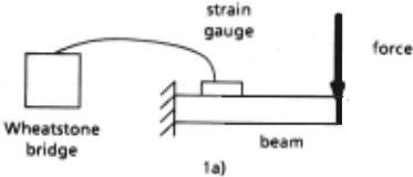
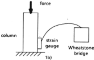
Design plans define a search space as well as ways of efficiently searching in that space. The dimensions of the search space are represented by variables that correspond to the parameters of the artifact to be designed. For example, in the domain of transducers variables are used to represent different properties of components such as the length and material of the beam, and the strain on the strain gauge (see fig. 1 for a diagram of a transducer whose characteristics will be presented in detail in the next section). Pieces of knowledge that are used to assign values to variables are represented by methods. Some of the methods calculate the values of a variable in terms of values of other variables. Other methods, generators, assign values from a set of possible choices (e.g., the material can take values mat1 to matn). Methods may also include heuristics for making plausible choices or taking optimality considerations into account. For example, the method for deciding the material might specify that mat1 is a good initial choice based on experience. Plans also contain constraint expressions that express relations between variables that must be maintained during the design process, e.g., the expression "strain<maxstrain" indicates that the strain in the strain gauge should be maintained below certain threshold. Finally, advice expressions are used to represent possible ways of repairing a partial design when there is a constraint failure.
The different elements of a plan as described above are structured around goals, which serve several purposes in the plan . representation. First, goals are used to index all the knowledge relevant to making a decision about a design variable. This is made possible by creating a goal for each design variable, ideally as a one-one mapping, i.e., a unique goal for each variable and only one variable per goal. Attached to a goal are all the methods for making a decision about that variable, as well as constraints which are applicable. This indexing allows the plan interpreter to select the most suitable method for making the decision. It also allows the applicable constraints to be checked as early as possible. The same indexing feature also allows advice for revising a variable to be sent to the unique goal responsible for making a decision about that variable.
The goals are also used to represent the ordering heuristics which are helpful in selecting the order in which the variables are decided. A partial order might be directly represented at a goal in terms of dependencies on other design variables or computed from the particular method which is run. Order information helps improve the efficiency of the constraint satisfaction process by allowing more constrained variables to be decided before less constrained ones. Ordering knowledge may come both from experience as well as from an analysis of the constrained-ness of the variables.
Finally, goals can be used to remove an important cause of inefficieny in constraint satisfaction. This is the case of n tightly-coupled variables in which the variables are so constrained that an attem'pt to find consistent solutions, which starts with a subset of these variables and then propagates the partial solution over the rest, will lead to much backtracking. We allow a single goal to be used to represent a tightly-coupled set of variables. This allows the constraints to be simultaneously resolved if suitable methods exist. It also creates a single decision point where all revision advice is posted.
Ill Generating a plan: An example
We will examine in detail, using examples from the domain of transducers, how a design plan can be generated. A force transducer is a mechanical device that is used to measure forces. Figure 1 shows two kinds of transducers consisting of a cantilever bending beam (column), a strain gauge and a Wheatstone bridge. The first kind of transducer behaves as follows: when the force to be measured is applied to the beam it produces a strain on it (a local deformation). This strain generates a strain on the gauge attached to it, which alters its electrical resistance. The change of electrical resistance, in turn, generates a change of voltage in the Wheatstone bridge, which can then be translated into numbers on a display, representing the magnitude of the force. The transducer has to be designed in such a way that for forces with magnitude on a certain range the relations between the magnitude of the force, strain, change of electrical resistance, and so on, are linear, so that the change of voltage in the Wheatstone bridge is linear with the magnitude of the force. This allows us to measure the magnitude of the force in terms of a change of voltage.
The specifications for a transducer to be designed indicate the range of the magnitude of the forces to be measured. Other specifications vary with the problem. There might be specifications about the desired. precision of the transducer, desired sensitivity, restrictions on the weight, restrictions on the size, range of temperatures for which the transducer must be operational, etc. Optionally, the top level configuration of the transducer might be given, i.e., the higher level components of the transducer. For instance, one could specify that a transducer should consist of a cantilever bending beam, a strain gauge and a Wheatstone bridge, which corresponds to the case of figure Ia. Specifications for an example transducer are given in figure 2.
F: maximum force to be measured, in pounds
MWT : max weight, in pounds (WT < MWT)
MLD: max lateral displacement of the beam, in inches, (LD < MLD)
ML: max length, in inches
OSC : output of supporting circuit, in voltsllb
P: precision, in pounds
Fig. 2 : Some of the variables that are specified in a typical force-transducer problem
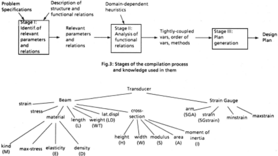
The process of generating a design plan can be decomposed into three stages, as shown in figure 3. The first stage takes into consideration the problem specifications and descriptions of classes of artifacts, and determines the parameters and functional relations that are relevant for a particular problem The second stage performs an analysis of the functional relations and uses domain-dependent heuristics to determine an ordering on the assignment of values to parameters, selects methods for assigning the values, and detects certain kinds of tight coupling between variables. The last stage maps the different elements produced by the previous stages into a design plan.
A. Stage 1: Determining relevant parameters and functional relations
In designing an artifact it is necessary to determine the parameters and functional relations relevant to the problem, i.e., the parameters that must be designed and the relations that must be taken into account during design. This can be accomplished in two steps. First, all the parameters and functional relations that need to be considered in a design situation are obtained . S~cond, the problem specifications are utilized to determine whether they affect the relevance of some of the parameters and relations obtained in the first step.
Identifying always-relevant parameters and relations
Let us assume that we have available descriptions of artifacts consisting of the structural decomposition of the artifact and a set of functional relations. Further, assume that the top level configuration of the desired transducer is given (e.g., the configuration depicted in figure 1a). Either this configuration is included in the specifications or has been generated by an earlier stage of the design process, during conceptual design. The given configuration. is used to determine the structural decomposition for that kind of transducer (see figure 4) . The structure of the artifact can then be used to derive an initial set of parameters and access a set of functional relations associated to them (see figure 5). This is accomplished by having the functional relations indexed by all the parameters (properties of the components of the artifact) occurring in the relations.
stress '" F*SGAJS (stress on the beam at the position where the gauge is attached)
strain · stress/E (the strain of the beam is a function
of the stress and the elasticity of the material)
SGstrain · strain (the strain on the gauge is equal to
the strain on the beam)
minstrain < SGstrain < maxstrain (the strain on the
gauge must be within certain range)
E · f3(M)
(elasticity of a material)
D · f4(M) (density of a material)
S · f1(W,H) (expression for the modulus of cross-section)
WT · L *A *D (weight of beam)
Fig. 5.: Some of the functional relations for beam transducers. Refer to fig.4 for relating the variables to the structure of the transducer
The parameters and relations obtained in this way are of two types. The "always-relevant" parameters and relations are those that capture important aspects of the functionality of the transducer and are always relevant to problems of these kind. Examples of these are the relations between the applied force and the stress on the beam, and between the strain in the gauge and its change of electrical resistance. These are the relations that determine that the transducer can be used to measure forces in terms of changes of electrical resistance. The "possibly-relevant" parameters and relations are those whose relevancy depends on the given specifications, which vary from problem to problem.
Determining how the specifications affect the relevance of possibly-relevant parameters
The second step of this stage consists of determining which of the possibly-relevant parameters and relations are made relevant by the given specifications. The basic criterion is that if the specifications contain restrictions on a possibly-relevant parameter, then the parameter become~ relevant. For instance, in the specifications given in figure 2 there are restrictions on the weight of the transducer (WT < MWT), and on the displacement of the beam caused by the application of the force (LD < MLD). The weight and lateral displacement initially are not relevant parameters as they do not contribute to the functionality of the transducer. But the restrictions on these parameters given in the specifications, which presumably are restrictions imposed by other components of the larger system in which the transducer is embedded, make them relevant in the current problem.
Once a parameter becomes relevant it is necessary to determine how it is related to the other relevant parameters, and how these relations affect the relevance of the rest of the parameters. The new parameter must be connected with the previously found relevant parameters through a chain of functional relations. These connections may involve other parameters, which in turn may participate in other relations with additional parameters, and so on. In the examples we have analyzed we have found that new parameters are related to existing parameters by means of equalities (Functional relations are of two kinds: equality relations, e.g., z = f(x,y), and inequality relations, e.g., t > f(x,y)). For example, suppose that pt, .. . ,pn are relevant parameters, and z is added as a new relevant parameter. Then, either z = f(pi,pj, ... pm), or z may be derived from other intermediate parameters which are in turn derived through equality relations from relevant parameters. In this case, all the intermediate parameters as well as the equality relations between them become relevant. In our work reported here we have considered only this special but common case, and have not addressed the most general situation where several paths can be found between the new parameter and the relevant parameters, in which also inequality relations are present that rnay alter the relevance of other parameters.
B. Stage II: Analysis of relevant relations and application of heuristics
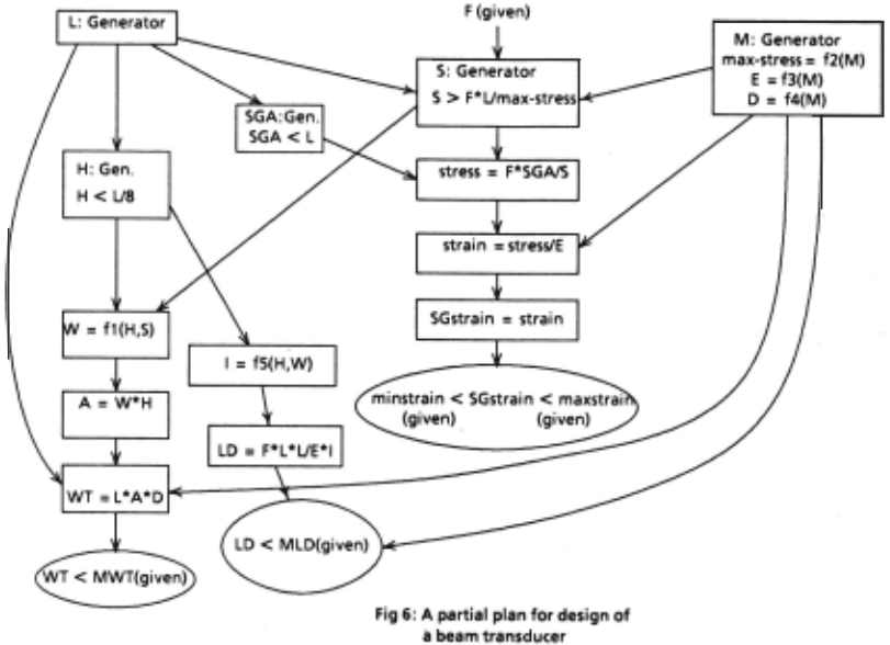
The purpose of this stage is to analyze the set of parameters and relations previously obtained and to create the "skeleton" of an efficient design plan, which in the next stage will be mapped into a full-fledged design plan interpretable by the problem solver. (Figure 6 represents the skeleton of a plan for designing the example problem). Domain-dependent and domain-independent heuristics are applied to determine grouping of variables, an order of assignment of values to parameters, and methods for assigning those values.
Decomposing the set of relevant parameters into tightly-coupled sets
The first step is the identification of sets of tightly-coupled parameters, i.e., parameters that are highly interdependent and should be designed together (see Section II). This step decomposes the set of relevant parameters into appropriate subsets. Often domain-dependent heuristics are available for this purpose. It is also possible to use domain-independent heuristics. For example, if several parameters are related to the same parameter p by equality relations, then the set of all these parameters, including p, is considered to be tightly-coupled. Furthermore, inequality relations between parameters in a tightly-coupled set are also associated with the set. In particular, any inequality relation relating one or more of the parameters in the set to parameters that appear first in the order of assignment of values, is associated to the set. This ensures that if any of these relations is violated all the parameters in the set will be recomputed, rather than only p and the ones involved in the violated relation(s). This reduces significantly the amount of backtracking necessary to satisfy all the relations.
Determining order of assignment of values and methods
The next step determines the order in which variables are assigned values. First, from the specifications we can determine the parameters whose values are initially known (e.g., force F in figure 6). Utilizing equality relations it is possible to determine other parameters that can be derived from them. Second, domain-dependent heuristics that contain order information and information about methods for assigning values can also be used. For example, a heuristic could indicate that the design of a beam transducer should start by proposing a length for the beam taking into account restrictions imposed by the specifications. Another heuristic could indicate that the material of the beam should also be selected at the beginning of the process, choosing first a standard material, from the list of possible materials (see figure 6).
Once a method for assigning value to a parameter is determined, the equality relations can again be used to see whether additional parameters can be derived. This process is repeated for every new parameter. After these heuristics are utilized we are left with a partial order for a subset of the parameters, and with methods for assigning values to some of them.
When no more equalities are available and still there are parameters whose values have not been assigned, the inequality relations can be used. For example, consider the "F*LJS < max-stress" · relation. If F, L, and max-stress are known, this relation can be used to generate values for S: "S> F* 1,/max-stress". (See figure 6).
Attaching inequality relations to parameters
After this step is performed, it is possible that some of the relevant inequality relations may not have been used. For each of these relations, the parameter that participates in the relation that is assigned value last in the order determined in the previous step, is identified. The relation is then added to the plan by attaching it to the node that contains that parameter. If the relation contains parameters that are in parallel branches of the partial order between parameters, then the functional relation is attached to a new node, and is connected to the nodes for those parameters. This ensures, first that when the constraint is tested by the problem solver all the parameters that participate in the relation have already been assigned values, and second that the constraint is checked as soon as possible.
Notice that a different plan would have been created for a different set of specifications which is an indication that the plan is sensitive to the characteristics of the particular problem. For instance, if the specifications for a problem impose tight restrictions on the size of the transducer, i.e., its length, width and height, a domain-dependent heuristic would have determined that the parameters of the cross-section of the beam should be designed first. Then, the maximum allowable stress (max-stress) would be determined using the relation on the modulus, under a different form (max-stress>F*LJS). Finally, the material would be selected taking this max-stress into account. Thus, the order in which variables are assigned values and the methods used for that · purpose in the new plan, are different from those of the original plan.
C. Stage Ill: Generating a plan
The skeleton plan that was developed in the previous stages is now mapped into a design plan. The relevant parameters are mapped into variables of a plan. The methods for assigning values to variables are mapped into appropriate kinds of plan methods, such as generators and calculations (e.g. the methods for assigning values to material (M) and to stress, respectively, in figure 6). Then the goals of the plan are created, and variables, methods and constraints are. attached to them, taking into account the semantics of plans. Typically, a goal will have only one variable attached to it, as well as one method for assigning values to that variable. If in the previous stage a constraint was attached to a parameter, then it will be attached to the goal corresponding to that parameter. Sets of variables corresponding to sets of tightly coupled parameters are attached to a single goal, together with the corresponding constraint. At the end of this process all the elements of the design plan have been tied together in a network of goals.
It should be noted here that a plan doesn't specify a single solution to a design problem, but rather a set of solutions. This is because generators, that are used to assign values to some ot"the variables, can produce a different value from their specified sets of values each time that they are activated. Also, an important property of a plan is that the problem solver can back up to a goal if it needs to revise a decision made at that goal, e.g., when a constraint has been violated. These two characteristics allow plans to guide the constraint-satisfaction process.
D. Current implementation of the compilation process
We have developed a preliminary implementation of the process for generating plans for certain kinds of the domain of force transducers, including the beam and column configurations. In this implementation, a class of artifacts is described in terms of descriptions of classes of components, which in turn specify the classes of their subcomponents and their properties. We assume that the top-level configuration of the desired artifact is available. The description of the configuration is used to index into the description of the structure of known classes of artifacts to obtain an initial set of properties. From these properties their associated fuoctional relations are accessed and collected. The process then continues as exemplified in section III.A. For the second stage of the process we have concentrated on making use of domain-dependent heuristics, leaving for a later version the implementation of some of the domain-independent kinds of analysis. The last stage of the current implementation creates design plans that can be processed by the constraint satisfaction engine of the Pride system.
IV Discussion and Conclusions
In this paper we have identified a two-stage process for representing domain knowledge and using it to design suitable artifacts, and have described a method for compiling different kinds of knowledge from a stage I representation into a stage II plan for constraint satisfaction. Two distinct arguments have been made for knowledge compilation. In this section, we examine these arguments in more detail and try to relate them to different characteristics of problem domains.
The first argument for compiling from stage I to stage II can be made on the grounds of maintainability of knowledge. A stage I representation allows different kinds of knowledge such as the structure of artifacts, functional constraints, and problem solving heuristics to be separately represented . Thus, appropriate representational schemes can be devised which would allow ·suitable knowledge editing and browsing tools to be developed. Under maintainability criterion alone, stage I representations are viewed as an easier-to-maintain representation, while stage II is viewed as optimized for execution. However, no problem solving goes on during compilation.
The second argument for compilation is based on the need to tailor a stage II plan to the requirements of specific design problems. Under this criterion, the compiler is not merely transforming one representation into another one but also carrying out some of the reasoning required by the design task. In particular, the compiler has to select the relevant d~ign variables and decide which constraints are relevant to the pro~ em at hand. This creates a closer bond between the compiler and the problem
\
solver used in stage II. For example, consider a situation where the problem requirements can be satisfied by more than one top-level configuration of transducer components. In such a case, the compiler would select one of the configurations and build a plan. However, detailed execution of the plan may show the configuration to be unsuitable. This requires an ability to back up to the compiler and select a different configuration. Notice, however, that this kind of reasoning is already performed by the stage II problem solver. This would seem to indicate a more iterative relationship between the plan compiler and plan problem solver.
Another important point in relation with the applicability of the compilation process is that in many domains it might be possible to develop a single plan or a small number of such plans that cover a large number of problem instances in the domain. In this situation the compiler is used purely for maintainabi lity reasons, leaving all reasoning with the plan interpreter. In other words, the compiler is only used to help in maintaining the knowledge base and not in compiling out certain_ kinds of reasoning. This observation is based on a comparison of the pinch-roll paper transport (PRPT) and force transducer (FT) domains. Knowledge about the former domain can be largely captured by a single plan with local variations. The latter domain, however, requires different plans for different problems. A comparison of the two domains seems to indicate that the problem-independent knowledge is more stable for PRPT problems than it is for FT problems. In other words, the relevant constraint expressions are more or less the same for all PRPT problems, much more so than they are for FT problems.
Acknowledgments
We would like to give special thanks to Walter Wang for many discussions on design issues and for having familiarized us with the transducer domain. We would also like to thank Felix Frayman for many discussions on the notion of compilation.
@inproceedings{ijcai1987p110,
  title     = {Compiling Design Plans from Descriptions of Artifacts and Problem Solving Heuristics},
  author    = {Araya, Agustin A. and Mittal, Sanjay},
  booktitle = {Proceedings of the Tenth International Joint Conference on
               Artificial Intelligence, {IJCAI-87}},
  publisher = {International Joint Conferences on Artificial Intelligence},
  editor    = {John McDermott},
  pages     = {552--557},
  year      = {1987},
  note      = {Knowledge Representation},
  url       = {https://ijcai.org/proceedings/1987/110},
}
TY - CPAPER TI - Compiling Design Plans from Descriptions of Artifacts and Problem Solving Heuristics AU - Araya, Agustin A. AU - Mittal, Sanjay T2 - Proceedings of the Tenth International Joint Conference on Artificial Intelligence, IJCAI-87 PB - International Joint Conferences on Artificial Intelligence PY - 1987 SP - 552 EP - 557 UR - https://ijcai.org/proceedings/1987/110 ER -Copied
Machine-readable versions of this paper, for tools and AI agents:





