Analysis of Uncertainties in a Structure of Parts
Proceedings of the Ninth International Joint Conference on Artificial Intelligence. Robotics. Pages 1113-1114.
© 1985 International Joint Conferences on Artificial Intelligence
Abstract
A structure built from parts will not fit perfectly. The amount of uncertainty in the relative Positions of the parts can be predicted from the dimensions of the mated parts and their tolerances. The tolerances and sizes of the parts• features are analysed for each possible contact in turn to find constraints on the part positions. The combined effect of these constraints is then found allowing decisions to be made on whether the parts fit satisfactorily. Applications include tolerance checking during design and off-line programming of robot assembly.
Full text extracted automatically from the PDF; figures, tables and equations may differ. The PDF is the version of record.
ANALYSIS OF UNCERTAINTIES IN A STRUCTURE OF PARTS
Alan Fleming
Department of Artificial Intelligence University of Edinburgh, Forrest Hill Edinburgh EH1 2QL, UK.
always be able to fit as shown and also how much slop could occur. At the present time (APril '85) a system has been built that will solve the problern though ignoring tolerances. The inclusion of tolerance analysis is in progress.
A part is defined as a set of features which are simple geometric surfaces such as finite planes or cylinders. The boundary of each feature is known. A structure is defined by the contacts that can occur between pairs of features. Each possible contact between features is referred to as a relationship. Similar representations of Parts and structures are used in the off-line robot programming system, Rapt, designed in the Department of Artificial Intelligence at Edinburgh University [2]. Rapt makes inferences over the relationships to find the actual positions of the Parts. Its results do not take into account poorly fitting parts or imperfectly formed parts but, in the work presented here, its results are used as nominal positions of the parts.
Each relationship puts possible positions of the constraints are combined and the possible positions of one any other can be found. constraints on the parts involved. The propagated so that part with respect to
Other work has dealt with the propagation and build up of uncertainties. Brooks [1] Propagates uncertainties in the form of inequality constraints through a robot plan and verifies that required conditions hold. Taylor [10] derlves constraints on the possible positions of parts from the relationships between their features and Propagates these through a structure of parts. Much work on robot planning has assumed the presence of uncertainty information (6,7,10]. Discussions on the suitability of a given tolerance scheme for a single part may be found in [3,4,5]. There is a considerable body of knowledge and tradition involved in tolerancing and the standards used may be found in [11]. Requicha [8,9] has formalised and generaliSed standard tolerancing practice to produce representations of tolerance types which are useful for deciding how toleranced parts interact.
II TOLERANCE REPRESENTATION
Requicha's ideas [8,9] on representation and semantics are tolerance useful for
ABSTRACT
A structure built from parts will not fit perfectly. The amount of uncertainty in the relative Positions of the parts can be predicted from the dimensions of the mated parts and their tolerances. The tolerances and sizes of the parts· features are analysed for each possible contact in turn to find constraints on the part positions. The combined effect of these constraints is then found allowing decisions to be made on whether the parts fit satisfactorily. Applications include tolerance checking during design and off-line programming of robot assembly.
I INTRODUCTION
Design specifications of mechanical parts usually include tolerances. A tolerance is a variation in a dimension or a statement about how well formed a surface must be. Since the shape of the parts is not exactly known it is difficult to know whether they will always fit properly. During design it must be verified that the parts of the structure never interfere and never fit too loosely. Similar questions also arise in off-line programming of robot assembly.
This paper describes a system to analyse a structure of toleranced parts. A real part which has been manufactured to the tolerance specification will be called an "instance" of the part. The system finds whether the parts will ever interfere or if they ever fit too loosely. It takes into account that some instances of the parts fit more tightly than others.
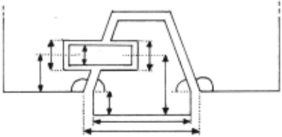
Diagram solvable by shown in the system could shows a problern that would be the system. Each dimension and angle diagram would have a tolerance. The find whether the spigot and peg would deciding how toleranced parts interact. He formalises standard engineering practice. His definitions allow the same types of tolerance to be aoPlied to any shape of feature. The types include form, size , orientation and position. For example a form tolerance applied to a flat surface is equivalent to the conventional tolerance of flatness but when applied to a cylinder is equivalent to tolerance of cylindricity.
The basic approach for defining tolerances is to use 3-dimensional tolerance zones . If an actual feature satisfies a tolerance specification then it must lie in an appropriately defined tolerance zone. A tolerance zone , in the case of a nominally cylindrical feature, is an infinitely long cylindrical shell. Different types of tolerance are defined by constraining some or all of the size, thickness or position of the shell. For example the tolerance zone of a size tolerance on a cylinder has fixed thickness and radius but variable position.
In the system described here, each feature is given a tolerance specification consisting simply of oarameters for each tolerance type.
Datums are used for defining the position of tolerance zones . The tolerance zone is olaced at the correct oosition with resoect to the relevant datum. Each oart has a master datum system. Other datums can be defined with resoect to features and their position depends on the oosition of the feature. A comolex network of features and datums may exist so that the tolerance allocated to one feature may have unexoected effects on other features. Ingham [6] has done work on oredicting the prooagation of tolerances through such a network.
III POSITION UNCERTAINTIES
The uncertainty in oosition of a part in a structure can be described as constraints on the degrees of freedom of the oart. A coordinate system in the part can be used to define six degrees of freedom by taking three translations along the axes and three rotations about the axes. A variable may be associated with each translation and rotation. These variables shall be referred to as "degree of freedom (DOF) variables".
For example, analysis of the structure in diagram 2, ignoring tolerances, gives:
-0·05/6 0·05/6 .
8 reoresents rotation about the origin of the coordinate system. This form of inequalities is used throughout the system . Standard methods, which deoend on the shaoe of the features, are used for deriving the coefficients. The y constraints in the above inequalities are found by considering the situations in which a corner of the hole is in contact with the oeg . Note that the coefficients in the inequalities for y deoend on the coordinate system used.
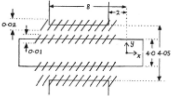
Peg in hole with position tolerances. The nominal parts are shown with shaded areas to indicate tolerance zones in which the actual surfaces must lie.
DIAGRAM 2
Considering tolerances, each instance of the structure is different and so the bounds on the DOF-variables vary between structure instances. This is represented by putting extra variables in the bound exoressions. So, for example, constraints on DOF-variable, y, now have the form,
where p and q are the new variables. From the diagram, constraints can be found on p and q. The most extreme values for y in any assembly instance occur when the peg is at its smallest and the hole is at its largest. The extreme values are seen to be ±[4 ·05-4+0·02+0 ·01)/2 ±0·04 and so -0·04~p~q~0·04.
However, due to size tolerances, these values may not be attainable in the same structure instance. Size tolerances limit the amount of variation in sloo that can occur and so out bounds on the difference between p and q. In general the form of constraints on p and q is,
L,U,T and S are numbers derived from consideration of the different tolerance tyoes. There are standard methods of derivation which deoend on the shape of the features.
IV COMBINING AND PROPAGATING CONSTRAINTS
Ultimately it is required to find constraints on the position of one part with resoect to some other. The constraints derived from individual relatlonships are combined and orooagated as described below. Using both techniques, kinematic looos can be dealt with.
A. Combin ing constraints.
There are orten several relationships between two oarts. The set of possible positions allowable by all the relationships together is the intersection of the sets of possible POSitions allowable by the individual relationships. The set of allowable positions is described by the conjunction of the constraints from the individual relationships. However, initially each set of constraints applies at a different coordinate system. There is an algorithm that changes the form of a set of inequalities to make them applicable to a different coordinate system.
Before combining relationships between two parts the build up of position tolerances between the features must be found. One of these is made a "master" relative to which the variation in position of the other features is found.
B. Propagating constraints.
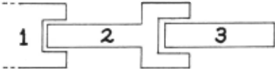
Constraints can propagate along a chain of parts and relationships. For example, in diagram 3, we may be interested in constraints on part 3 with respect to part 1. There is an algorithm to deal with the general case analytically.
There may be position tolerances linking the ends of part 2. The variation in position of one end with respect to the other must be found before Propagation can be applied.
V VERIFYING DESIGN REQUIREMENTS
The result of applying the above inferences is to produce constraints on the position of one part with respect to some other. The constraints, in two dimensions, take the form,
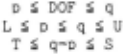
where L,U,T and S are numbers and DOF is a degree of freedom variable. [There may also be terms involving the angular DOF-variables in the first of these inequalities.J Although, initially there may be more than one such set of inequalities for each DOF they can easily be reduced to one set.
The values of L,U,T and S give useful information. For example, T represents the maximum tightness that could occur in any instance of the structure for that degree of freedom. If T<O then the parts will sometimes not fit. S represents the maximum possible sloppiness and L and U represent the extremes of displacement that could occur in any instance of the structure.
VI CONCLUSION
This paper describes a system to analyse slop in a structure of toleranced parts. There are two stages of reasoning. Firstly constraints are found from each relationship. The existence of tolerances introduces variables and constraints not required for nominal parts. Secondly the constraints are combined and Dropagated to find the possible relative positions of two parts.
RE FE RENCES
- [ 1 J Brooks, R.A., "Symbolic Error Analysis and Robot Planning", Memo AIM-685, Stanford University, 1983.
- Corner, D.F., A.P. Ambler and R.J. Popplestone, "Reasoning about the Spatial Relationships Derived from a Rapt Program for Describing Assembly by Robot", Research Paper No. 191, Department of Artificial Intelligence, University of Edinburgh, 1983.
- Hillyard, R., "Dimensions and Tolerances in Shape Design", Tech. Report No. 8, University of Garnbridge Computer Laboratory, 1978.
- (4] Hoffman, P., "Analysis of Tolerances and Process Inaccuracies in Discrete Part Manufacturing", Computer Aided Design, Vol 14 No. 2, March 1982.
- [ 5] Ingham, P. C., "A Computer-Aided Tolerance System", City of Birmingham Polytechnic.
- Lozano-Perez, T., "The Design of Assembly System", Massachusetts Technology A.I. Lab, Technical 1976. a Mechanical Institute of Report 397,
- Lozano-Perez, T., M.T. Mason & R.H. Taylor, "Automatie Synthesis of Fine-Motion Strategies for Robots", The International Journal of Robotics Research, Vol 3 No. 1, 1984.
- Requicha, A.A.G., "Toward a Theory of Geometrical Tolerancing", Tech. Memo No. 40, Production Automation Project, University of Rochester, March 1983.
- Requicha, A.A.G., "Representation of Tolerances in Solid Modelling: Issues and Alternative Approaches", Tech. Memo 41, Production Automation Project, University of Rochester, August 1983.
- Taylor, R.H., "A Synthesis of Manipulator Control Programs from Task-Level Specifications", Memo AIM-282, Stanford Artificial Intelligence Laboratory, 1976.
- British Standards, BS:308, "Dimensioning and tolerancing Part 3 - "Geometrie tolerancing" Part 2 of size" and
@inproceedings{ijcai1985p228,
  title     = {Analysis of Uncertainties in a Structure of Parts},
  author    = {Fleming, Alan},
  booktitle = {Proceedings of the Ninth International Joint Conference on
               Artificial Intelligence, {IJCAI-85}},
  publisher = {International Joint Conferences on Artificial Intelligence},
  editor    = {Aravind Joshi},
  pages     = {1113--1114},
  year      = {1985},
  note      = {Robotics},
  url       = {https://ijcai.org/proceedings/1985/228},
}
TY - CPAPER TI - Analysis of Uncertainties in a Structure of Parts AU - Fleming, Alan T2 - Proceedings of the Ninth International Joint Conference on Artificial Intelligence, IJCAI-85 PB - International Joint Conferences on Artificial Intelligence PY - 1985 SP - 1113 EP - 1114 UR - https://ijcai.org/proceedings/1985/228 ER -Copied
Machine-readable versions of this paper, for tools and AI agents: