Using Surfaces and Object Models to Recognize Partially Obscured Objects
Proceedings of the Eighth International Joint Conference on Artificial Intelligence. Vision. Pages 989-994.
Abstract
This paper describes an approach to object location based on matching model regions to surface image regions . These matches . together with objectmodels . provide hypotheses about the 3D location of the objects containing the recognized surfaces . When a hypothesis is complete. the program describes the matched data and model surface boundaries in termsof the raw. model. These descriptions are used used to verify the physical consistency of the hypotheses and to explain extra or hypothesize missing features caused by obscured components .
- X: -25 Y:l24 Z:440 Rotation:O.l2 Slant:O . l3 Tilt:5.56 jntl:O.B3 jnt2 : 0.BB jnt3:4.54 11. References
- Binford, T.O., "Inferring Surfaces From Images" , Artificial Intelligence, Vol. 17, pp205-244, 1981
- Binford, T.O., "Survey of Model-Based Image Analysis Systems", Int. J. of Robotics Research, Vol. 1, #1, pp18-64, 1982
- Brooks, RA., "Symbolic Reasoning Among 30 Models and 20 Images", Stanford AIM-343, 1981
- Freuder, E. C., "A Computer System For Visual Recognition Using Active Knowledge", Proc. 5th Int. Joint Coni. on AI, pp671-677, 1977 IJCAI
- Grimson, W.E.L., "From Surfaces to Images: A Computational Study of the Human Early Visual System", MIT Press, 1981
- Pentland, A.P., "local Computation of Shape", Proc. European Coni. on AI, pp199-204, 1982
- Roberts, l.G., "Machine Perception of Three-Dimensional Solids", in Optical and Electro-Optical Information Processing", pp159-197,
References were extracted automatically from the PDF and may contain errors.
Full text extracted automatically from the PDF; figures, tables and equations may differ. The PDF is the version of record.
ABSTRACT
This paper describes an approach to object loca tion based on matching model regions to surface image regions. These matches. together with object models. provide hypotheses about the 3D location of the objects containing the recognized surfaces. When a hypothesis is complete. the program describes the matched data and model surface boundaries in terms of the raw. model. These descriptions are used used to verify the physical consistency of the hypotheses and to explain extra or hypothesize missing features caused by obscured components.
l. Introduction
The most important recent work In high-level v1s1on <ACRONYM [3]) has demonstrated the impor tance of embedding object models and an understand ing of the scene-to-image transformation in an intelli gent vision program. With these comp.onents. a pro gram can predict how an object will appear given its current beliefs about the scene. rather than having to rely on image models <or. more likely. a feature space representation of these views> . Concurrently. much low-level vision research has been attempting to pro
vide a surface-based description of images.
This paper describes a program <IMAGINE> which matches surface regions to object models to recognize and locate projections of three dimensional objects in two dimensional images. The approach is data driven. with three major stages. The first stage matches Image regions to model surfaces. with the goal of estimating the 3D orientation parameters for the image region. This information is used to hypothesize specific object surfaces. The second stage relates the hypotheses · according to the structural relationships embodied in the object models. The third stage veri fies that the hypothesized objects are consistent with real world constraints. such as boundary adjacency and surface ordering. This process requires calculat ing descriptions of the predicted surfaces and associ ated data regions. Recognition is considered success ful if a set of data is found that adequately accounts for all features of a model. In particular. this requires the program to reason about object back sur faces. tangen't surfaces. small features . obscured features and non-rigidly attached subcomponents.
This work was supported by a post-graduate student ship from the University of Edinburgh. Thanks also go
to J.A.M. Howe and R.J . Beattie.
USING SURFACES AND OBJECT MODELS TO RECOGNIZE PARTIALLY OBSCURED OBJECTS
Robert B. Fisher
Department of Artificial Intelligence University of Edinburgh
In short. the program has four goals:
- to locate instances of specific 3D objects in 2D
- images.
- to locate images features corresponding to all features of the model. or explain why the image features are not present.
- to ver ify that the features are consistent with the geometrical and topological predictions made by the model . and
- to extract the parameters needed to fully charac terize an object 's scene position . including any associated with flexibly connected objects.
Coping with obscured features of objects is an important point of this work. This has required work in two areas : first. in deciding what are relevant aspects of obscured objects <ie. what features . disap pear and what new ones appear> . and second . in extracting information about those features. This second point has required work on extracting 3D posi tional information from surface shapes and descriptions of surface and image regions.
This paper discusses · the model and the reason ing rules used to analyze the main example image that of a robot upper and lower arm assembly.
b What does "recognize" mean !!!. this context
The meaning of ' recognition ' is largely dependent on the goals of the recognizer: that is. what type of output is desired for what type of input. If the only brown objects in the environment are tables. then a program could find tables by looking for brown regions. To some extent. all recognition programs are just discrimination programs. of which the table recog nizer is a minimal such program. On the other hand. even the most sophisticated programs <e.g. ACRONYM [3]) are fundamentally the same: they attempt to find a set of evidence that Is consistent with their model of the object and for which there is no contradictory evi dence. The distinction Is largely one of sophistication - richer models. greater embedded knowledge about object structure relationships and more detailed match ings reduce the possibilities of false recognitions.
In general. recognition consists of four subactions:
- location of interesting data.
- selection of a model.
- instantiation and verification of model. and
- determination of object's location and orientation.
- in particular. th is program:
- Considers all data interesting. Thi s is mainly because the input has been previously seg mented into connected surface regions.
- Considers all models. This is mainly because model invocation is a research problem not addressed in this work.
- Attempts to fully instantiate the model. A model has slots for a set of structurally related sur faces and subobjects. The program either fi lls the slots or finds evidence to explain why they cannot be filled . <This is an important requ ire ment for an intell igent vision program.> Surface ~ lots are matched to image regions and sub structure slots are matched to previously recog nized objects. Fully instantiated hypotheses must pass a verification process.
- Locates and orients the objects in three dimen sions. The parameters come from estimating the transformation that maps a given model sur face to a given image region based on the shape of the image region . and then inverting the transformat ion from surface to object.
3. Surfaces
The project has concentrated on using surface reg ions as the primary data primitive. Though there are no programs yet that reliably and completely give a surface segmentation. it doesn ' t seem like a too distant possibility. Pentland's surface shape algorithm f6l. various stereo algorithms <e.g Grimson [5)) . optical flow. range finder systems and structured light systems all provide the information needed to construct a sur face map. <Surface depth. shape and orientation are all largely equivalent representations.>
There are many reasons for using surfaces as the primitive input data element at this level of analysis. First. irrespective of what interpretation is made. what is seen is the surface of objects. Second. as surface regions are matched to model surface regions. the semantics of the relationsh ip is s1mple: In unobscured situations. a six parameter geometric transformation plus a projection onto the Image plane. Third . the segmentation of a surface image into regions of uniform surface properties may be s1mpter. To some extent. any region of homo geneous image properties is likely to correspond with some subset of a uniform surface. <The reverse is not always true. as a shadow across a flat surface would create . two distinct regions.> There are many open problems on this topic. such as merging split reg1ons. scale of surface descriptions, etc. Fourth. surface regions lead to more accurate transformation parameter estimates <mainly because their size gives more accurate measurements> . Point to model match Ing and transformation inversion algorithms <e.g. Roberts [7)) . whi le elegant. are sensitive to image measurement errors. Worse. the loss of Information from using just points makes It difficult to determine the image to model correspondences correctly. Lastly. once surfaces are chosen as the desired primitive,
other Image boundary Information Is more useful :
- reflectance boundaries: surface detail
- obscuration: object limits. surface depth order
- shadow: surface location In three dimensions
- shape: surface relative orientation
The input used by the program is that of a sur face image segmented into regions of either planer or
simply curved orientation. Hence. the data is simpli fied in that we know all boundaries correspond to surface or shape discontinuities. Further . the boun daries form closed regions. The program could have used the surface depth or orientation information as part of its inputs. but it was decided to base the work just on the region shape.
This work uses structural three dimensional models of the objects it expects to find. The reasons tor this are discussed by Binford [2] : a capable vision system should know about objects. and how objects are seen in images. rather than what types of images an object is likely to produce. One difference between this work and that of Binford and Brooks <ACRONYM [3)) has been the choice of primitives used to construct the models. They use solid object ~odets <generalized cones> as the fundamental building tllock. and then deduce what image boundaries are produced. One problem with this is that what is seen is surfaces; hence it seems reasonable that the pre ferential representation for a vision system would make surface-based information explicit. <This argument is largely one of conceptual simplicity. in that it should be possible to automat ically deduce a surface representation from a solid representation . though not necessarily easily.> Another difficulty with the general Ized cone is that it seems to be a conceptually sim ple representation for only some object classes. though any one representation is probably not suffi cient for all tasks.
Surface primitives are constructed by specifying the boundary of the region. with the assumption that the surface is either planer or has a single axi s of curvature and fills the region inside the boundary.
Objects are described in a subcomponent hierar chy. with objects being composed of either connected surfaces or recursively defined sub-objects. The con nections are specified using a six parameter attach ment <x.y.z translations. rotation. slant and tilt) . These attachments can be rigid <all parameters specified in the modeD or may be flexible . Flexible attachments are handled by assigning the parameter a symbolic and which is bound value when the corresponding subcomponent Is added to the object hypothesis. Symbolic parameters are only used with attachments.
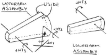
Figure 2 shows some of the model used for the example in section 9. The full model consists of the upper and tower main arms of a Unimation PUMA robot. The figure here just shows some of the model for the upper arm and external linkages. Figure 1 shows the part models and the coordinate frame loca tions. The variable "jntN" Is the symbolic parameter for the robot 's Nth joint angle. In the example. the FACE primitives define the surfaces by listing key boundary points <30> and whether they are joined by a line or simple oriented curve. The ASSEMBLY blocks define named structures. in terms of either other named structures or surfaces. The "AT << .. . >. C .. ))" portion describes the XYZ translation. rotation. slant.
tilt affixment reiRtionshio between the main and substructure reference frames.
ASSEMBLY upperarm =
uside AT «O.O.Ol.<O.O.O))
WITH uside AT «0.29.8. 10> .<0.3.142.1.57))
WITH uendb AT «0.0.1 Ol. <0.1.57 .3.14))
WITH uends AT ((61 .8.7.4.0).(0.1.57.0))
WITH uedge AT ((0.0. 10>.<0.-1 .57 .1.57))
WITH uedge AT (<0.29.8.0).(0.1.57 .1.57)) ;
FACE uside = <O.O.Ol LINE <19.6.0.0) LINE (61 .8.7.4.0) CURVE[0 .82.0.0] (61 .8.22.4.0) LINE <19.6.29.8.0> LINE <0.29.8.0> CURVE[-0.38.0.0];
Figure ~ = part Q! model used for the robot arm recognition example
5. Matching model surfaces to image ~ions
This process produces the main input used by the object recognition and construction process described in sect ion 6. Its inputs are the boundary of the image region and a description of the surface as given by the model. It has the goal of estimating the transformation parameters that relates the image to the model.
The visual motivation for this process is: the shape of an image region gives strong clues to the or ientat ion of the surface. ·In particular . the program compares the image region shape to the model sur- · face shape <using the boundaries> and attempts to extract measurements that lead simply to the desired parameters. The parameters are rotation . slant. tilt axis orientat ion . distance and x-y translation . The choice of rotation . slant and tilt as the orientation parameters was motivated by what information was easi ly found in an image of a transformed surface. The initial parameter est imation process is based on the following observations:
- rotation and XYZ translation of a surface do not alter its relative cross sect ional dimensions. and that slant does not alter them drastically. over the range of estimated slants <less than 1.3 radians>.
- the tilt axis lies approximately at the orientation of greatest slant distortion.
- the maximum distortion is an indication of the slant relative to the line of sight.
- the relative scaling of features between the model and image indicates the distance.
The heuristics used for the parameter estimation are:
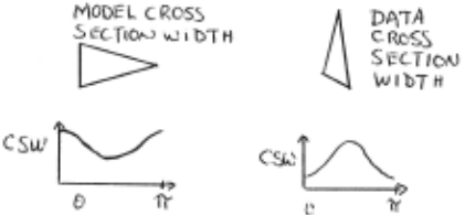
rotation - correlation of data and model cross sections. The peaks are potential rotation offsets. Figure 3 shows typical model and data shapes and their corresponding cross sect ion versus angle funct ions. Note that the data function is largely just the translated model function.
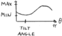
slant and !!.!.! - given an estimated rotation . create a rat io of maximum data to maximum model cross section widths as a function of cross section path angle. <Use of the maximum is a heuristic to relate approximately corresponding cross sections.l Slant. tilt and distance estimates come from the orientation of the minimum ratio. the rat io itself and the maximum ratio (figure 4) .
SL A/V T "' ARLCOS ( t"\l t--l (f<\ ~)() Di S T""" iji"\AX


distance - given rotation . slant and tilt. compute a ratio of data to model cross sections along the data region 's major and minor axes. Two dis tance estimates are made from the average and most common ratios. The final value is the average of these two and the previous esti mates. The major motivation for the use of three estimators is various sensitivities to obscu ration or parameter mis- estimation.
- ~ translation - align data and mode centers of mass transformed by the estimated parameters
An optimization phase is then entered. The evaluation function is the weighted distance of the predicted model boundary from the observed image boundary. Because of the expected accuracy of the various parameter estimates. optimization preference is given to the worst estimate in order of tilt. distance. slant and rotation . with the x-y translation always adjusted to best fit at each stage.
Note that the transformation relating a modeled surface to an image region is not always unique. especially when model symmetries. spatial quantization and inaccuracies of fitting numerical data are con sidered . Consequently. the parameter estimation pro cess may produce more than one hypothesis.
These heuristics gave reasonable parameter esti mates in 94 of 100 test cases recently. Given the tolerances in the matching process. the estimates are acceptable in the successful cases. Unfortunately cal culating these parameters is largely numerical and computationally expensive - mainly because of image parameter measurement and model-to-data boundary comparisons during the optimization phase.
~ Some rules for recognizing objects
Here. recognition is a construction process. At each stage. a hypothesized structure is under con sideration . This hypothesis may have several empty substructure slots . in which case the program will attempt to fill the slots in various ways. Or. the slots may all be full. in which case the hypothesis will be subjected to a verification process. Finally. the struc ture may be used to hypothesize another structure.
Currently. the processing of the hypotheses is exhaustive. and Is controlled by a first-in . first-out queue. The selection of which procedure to apply to a hypothesis is determined by a set of rules compiled from the set of meta-rules discussed below.
Some of the rules have binary right-hand-sides. When the matcher considers applying such a rule to a hypothesis. a prediction routine is called. Using the object models. this routine predicts where in the Image the second hypothesis needed for the matching might be found <c.f. Freuder 's Advice process [4Jl . Then . all hypotheses of the appropriate type from this location is paired with the current hypothesis node and the analysis routine Is invoked for each pairing.
The general produce with rules to definition. hypotheses instantiation. will processing philosophy is for the all hypotheses consistent with their the assumption that incorrect not be capable of full consistent
About two dozen rules exist at the current time. The point of having different rules . rather than a gen eral mechanism. Is that each can carry out the specific type of reasoning needed to solve a particular problem. The rules described below are some of those used in the example given in section 9:
RULE ~ <surface hypothesis> ~ <Image region>
This rule selects. among all model surfaces. those that meet various pre-screening conditions rela tive to the particular image region <mainly minimum size relationships) . Then. the parameter estimation process <section 5l is applied for each surface candi date. A surface hypothesis Is generated for each suitable estimate.
RULE .L <object hypothesis> <- <object hypothesis> <surface hypothesis>
This rule adds a new surface to an existing structure hypothesis. For the rule to apply, the global location of the new hypothesis predicted by the new surface has to be consistent with the previous hypothesis. The resulting hypothesis has all the previ ous Information transferred. Including variable bindings.
RULE ~ <object hypothesis> ~ <surface hypothesis>
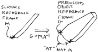
This rule produces a structure hypothesis for each modeled object that has th~ particular face as a rigidly connected subcomponent. The location of the hypothesis is calculated by taking the location of the face and inverting the attachment relationship to the main structure (figure Sl .
RULE ?.,: <object hypothesis> ~ <object hypothesis>
This rule fills slots corresponding to surfaces invisible because they lie on the back sides of the object. This is done by using the object model to predict the surface orientation. given the hypothesis's location and orientation.
RULE ;t <object hypothesis> ~ <object hypothesis>
This rule fills slots that correspond to near tangential surfaces on the front side of an object. Because of the severe slant distortion of such sur faces . parameter estimation is unreliable. Hence. the slots are filled with references to image regions that lie approximately in the right location and have approximately the correct size.
RULE ±.: <verified object> ~ <object hypothesis>
This rule Is discussed In detail In section 7.
RULE 9: <object hypothesis> <- <object hypothesis> <bound verified subobject>
This rule adds a new rigidly attached subassem bly to the current hypothesis. The location of the main assembly predicted by the new subassembly must be consistent with the previous hypothesis.
RULE .lQ.;_ <object hypothesis> ~ <object hypothesis> <bound verified subobject>
This rule adds a new flexibly attached subassem bly to the current hypothesis. The location of the new subassembly. with the previous hypothesis's loca tion and the model attachments. allows the calculation of the attachment relation that must exist between the structure and subassembly. If this Is consistent with the explicitly modeled parameters. then the match is acceptable. Any remaining symbolic parameters are then bound to the corresponding calculated values. in the context of the resulting hypothesis .
7. Verification and Description
When an object hypothesis Is fully instantiated.
the verification rule is applied . This is necessary because the hypothesis construction rules are tolerant in their checking <e.g. location and orientation param eter consistency> and allow a few unlikely fully instan tiated hypotheses to be formed . The major discrepan cies noted were: use of one image region to support several distinct surface hypotheses and the use of widely separated image regions to support adjacent surface hypotheses.
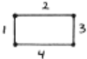
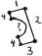
Part of the verification phase needs a description of the surface-to-image match. Two descriptions are created: that of the surface hypothesis as supported by the image region data. and that of the image region as accounted for by the projected surface hypothesis. The descriptions are given by identifying segments of the boundary of either the image or projected model surface region in correspondence with the description of the surface database model <example below>. This correspondence is found by:
- taking the boundary of the image region and calculating a similar boundary for the projected surface region Cwith segments identified by the model description labels>.
- identifying corresponding segments in the two boundaries by overlaying them and marking unlabeled segments. and
- creating a description of the correspondence by recording segment identifiers and segment end point locations Cwith some minor editing>.
In the robot image example <section 9>. there is a partially obscured surface In the robot lower arm assembly. In figure 6. we see how the model and image data are used to give the two descriptions.
2 ~


(d) labeled data description
Figure §. = description .2! image and matched surface boundaries
These descriptions are used partly In the general verification process. and partly for the handling of obscuration <section 8) .
The total verif ication process can then be sum marized as:
- check for all slots filled
- ensure that all surfaces still are <necessary adjustments> declared as back facing because of parameter
- ensure against duplicate use of image regions
- re-optimize parameter estimates <given better averages estimates as the initial inputs>
- describe visible surfaces cas above>
- for all visible surfaces predicted to have shared boundaries Cby the mod ell. ensure that the por tions of the surface descriptions corresponding to the shared boundary are compatible Ci.e. overlap>
- ensure that the object 's final predicted boun daries coincide well with the observed boun daries. This includes the obscuration analysis discussed in section 8.
_!L ~ with partially obscured objects
Any reasonable three dimensional scene analysis program has to cope with obscuration: objects always have backsides that the model predicts. but are never seen. There are two other forms of obscuration: the object may have self-obscured front surfaces (from either rigidly or flexibly attached subcomponents being closer to the viewer> and the object may be obscured by external. unrelated objects in the scene.
In the discussion below. only surfaces are con sidered . This is because the analysis has focussed on the use of surface descriptions. and because the objects can be described <directly. or recursively> in terms of their surfaces. Self-obscured surfaces are those obscured by other surfaces of the same object. External surfaces are those on unrelated objects.
Knowledge of the models. surfaces and the image formation process is the ultimate source of the infor mation needed to solve obscuration problems. Here. the initial use of this knowledge is during , surface description. Major deviations of the image boundary from the predicted model boundary are hypothesized to result from obscuring boundaries. The second usage is during object construction . If surfaces are only slightly obscured . then the model instantiation process proceeds normally. If they are greatly obscured . then the parameter estimation techniques will not be suc cessful. Then. the presence of a likely image region is considered adequate at this point.
The backside surface case is easily handled by examining the predicted surface normal.
Completely obscured surfaces require evidence of closer surfaces. to support their hypothesized existence. For self-obscured surfaces. the evidence comes from the prediction of other object surfaces. Evidence for external surfaces must come from elsewhere. This case has not been implemented yet. Possible evi dence may come from: other verified object hypotheses or low level feature cues <e.g. as in Binford [1]) .
Partially obscured surfaces get the greatest analysis. Because they are partially visible. they fill slots in the object hypothesis. As mentioned above. to do this. the hypothesis formation constraints are weakened. Unfortunately. weakening the constraints leads to the possibility of Incorrect hypotheses being formed. The major burden of coping with this and obscuration in general Is In the verification process <rule 4>. In addition to the verifications described In section 7. the routine has four obscuration-specific tasks:
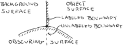
- to ensure that points where the data description becomes unlabeled are points where three Cor morel regions meet (figure 7l. These regions are: object surface. obscuring surface and back ground surface. This is a variation of the TEE test for obscuring surfaces . except that it has advantages in cases of coincidental alignments. in that it is based on surface ordering proper ties . rather than boundary topology.
- to ensure that unlabeled model boundaries are consistent with predictions of obscuring surfaces (figure 8l. In particular . this means that the predi cted missing boundary (from the model description> must lie completely outside the .a'ssociated image region . The hypothesis can be strengthened in the self-obscured case by showing that the missing segment lies within a region corresponding to a closer surface.
- to verify that unlabeled data description boun daries are consistent with obscuring surfaces (figure 9). That is. the unlabeled data boundary must lie completely within the region predicted for the surface. Again. the hypothesis can be strengthened in the self-obscured case by show ing that the unlabeled boundary lies on the boundary of a closer object surface.
- to verify that boundaries of undescribed regions coincide with predicted model boundaries
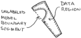
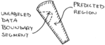
(figure 10) . This case has not been explored yet.
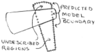
This type of reasoning complements that proposed by Binford [11. in that this uses the depth ordering pro perties of surfaces to provide clues for hypothesis verification . His approach uses similar reasoning for hypothesis formation.
~ Example
- Figure 11 shows a picture of a model of the upper and lower arm assembly of a Unimation PUMA robot. with the boundaries of the hand-segmented sur face regions. This image was used as the basis for the resu lts discussed in this section . The location of the model 's external coordinate frame origin and the value of the joint angle parameter are given below. The global coordinate system is centered at the focal point. with X horizontal. Y vertical and Z away from the viewer. All distances are in centimeters and angles are in radians.
| X: - 20 | Rotation:O.O | jntl:0.85 |
| Y: l24 | Slant : O. O | jnt2:0.84 |
| Z:443 | Tilt:O . O | jnt3 : 4 . 68 |
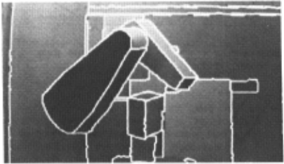
This image was hand segmented to give the major surface regions in the field of view. The seg mented image. the model shown in figure 1 and the meta-rules ce.g section 6> were then used as the external inputs into the program. The output of the program is a database of the hypotheses at various stages of instantiation. The only fully instantiated robot hypothesis was the correct one. For that solu tion . the global coordinate and the corresponding joint angle parameters were:
| X: -25 | Rotation:O.l2 | jntl:O.B3 |
| Y:l24 | Slant:O . l3 | jnt2 : 0.BB |
| Z:440 | Tilt:5.56 | jnt3:4.54 |
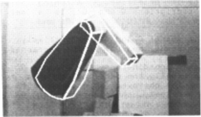
It is felt that the numerical solutions given by the program are reasonable. <The large tilt angle estimate discrepancy occurs because of the essentially zero slant estimate.> It is not apparent. but the results at various intermediate stages are often a lot worse. The accuracy results from averaging estimates from the six visible surfaces of the robot. The predicted surface boundaries of the final robot hypothesis node superposed over the raw image are shown in figure 12. <The obscured edge is not removed due to lack of a front-surface hidden line remover.> The picture shows that the numerical estimates are approximately correct . The fitting of model surfaces to data regions aligned boundaries well . but when the parameters esti mates from the various surfaces are combined . the boundary fit deteriorates. which shows in this figure.
10. Conclusions and Cl"iticisms - --
The results from section 9 show that the pro gram successfully identified · the robot assembly and made reasonable estimates of its location. orientation' and joint angle parameters. This can be attributed partly to the right choice of input data (i.e. surface regions and 3D object models>. and partly to the types of reason ing done at the various stages of analysis.
The program can be criticized on several points. First . its image surfaces must be largely planer for the current parameter estimation techniques to succeed. .Second. the modeling of surfaces doesn't account for the surface shape internal to the region boundary. Third . the program doesn't take advantage of the fact that surface segmentations will probably provide two or three parameter estimates directly Cslanttilt,distancel. Fourth. its models are non-generic <unlike ACRONYM>. and there is no simple mechanism <as yet> available for providing them. Fifth. its current dependence on hand-segmented images. while neces sary at present. makes the program difficult to ade quately evaluate. Sixth. the model invocation process currently considers matching all surface regions to all reasonable surface models. Because any reasonable model base and image will have many surfaces. a more powerful technique is needed. Seven. its rea soning is much more oriented to structural. than to visual understanding. The two major uses of image data were in the parameter extraction and the struc ture verification processes. with the rest of reasoning devoted to matching according to the object models. Eight. it's reasoning is largely undirected and thus leads to having a heavy computational cost. Finally. because it uses an exact parameter matching tech nique. with tolerance (threshold> based matching. rather than convergence of parameter ranges <c.f. ACRONYM> . it is subject to complete failures when parameter estimates are inaccurate. However. even though generous tolerances were needed . the process was selective enough to only allow a few hypotheses to get close to the verification stage.
On the other hand. because it uses a more rea sonable semantic primitive, surfaces. and because it uses constructive, task-specific reasoning . it can more completely recognize complex objects. In particular . the program successfully:
- located and identified a 3D object in a 2D image
- used surface regions and 3D object models to guide the process.
- extracted the 3D positional information. including the joint angles of a flexible assembly,
- fully instantiated and explained the model of the robot assembly. and
- handled some cases of self-obscuration correctly.
It is felt that the work described in the paper describes advances int the following areas:
- 3D parameter estimation from surface image region to model region matching.
- successful recognition of articulated objects. and
- better understanding of handling obscured surfaces .
11. References
- [ 1] Binford, T.O., "Inferring Surfaces From Images" , Artificial Intelligence, Vol. 17, pp205-244, 1981
- Binford, T.O., "Survey of Model-Based Image Analysis Systems", Int. J. of Robotics Research, Vol. 1, #1, pp18-64, 1982
- Brooks, RA., "Symbolic Reasoning Among 30 Models and 20 Images", Stanford AIM-343, 1981
- [ 4] Freuder, E. C., "A Computer System For Visual Recognition Using Active Knowledge", Proc. 5th Int. Joint Coni. on AI, pp671-677, 1977
- Grimson, W.E.L., "From Surfaces to Images: A Computational Study of the Human Early Visual System", MIT Press, 1981
- [6], Pentland, A.P., "local Computation of Shape", Proc. European Coni. on AI, pp199-204, 1982
- Roberts, l.G., "Machine Perception of Three-Dimensional Solids", in Optical and Electro-Optical Information Processing", pp159-197, 1965
@inproceedings{ijcai1983p230,
  title     = {Using Surfaces and Object Models to Recognize Partially Obscured Objects},
  author    = {Fisher, Robert B.},
  booktitle = {Proceedings of the Eighth International Joint Conference on
               Artificial Intelligence, {IJCAI-83}},
  publisher = {International Joint Conferences on Artificial Intelligence},
  editor    = {Alan Bundy},
  pages     = {989--994},
  year      = {1983},
  note      = {Vision},
  url       = {https://ijcai.org/proceedings/1983/230},
}
TY - CPAPER TI - Using Surfaces and Object Models to Recognize Partially Obscured Objects AU - Fisher, Robert B. T2 - Proceedings of the Eighth International Joint Conference on Artificial Intelligence, IJCAI-83 PB - International Joint Conferences on Artificial Intelligence PY - 1983 SP - 989 EP - 994 UR - https://ijcai.org/proceedings/1983/230 ER -Copied
Machine-readable versions of this paper, for tools and AI agents: