
Resolving Observer Motion by Object Tracking
Proceedings of the Eighth International Joint Conference on Artificial Intelligence. Robotics. Pages 792-797.
© 1983 International Joint Conferences on Artificial Intelligence
Abstract
A fundanental sub-problen of the task of interpreting the sonar data gathered by a 1nobile suhnersible robot vehicle is that of construe ting and ,~aintaining a stationary global reference frame in 1.rhich interpretation can take place. Such a frane may be established by tracking the 1aoveraents of objects in the local environment of the robot and using the data so obtained to deduce the notion of the observer. In a marine context, where currents nake it impossible to hold a vehicle stationary for any extended period, it is important to track the vehicle and object motion continuously in real time. In this paper the problem of establishing a stationary reference frame using noisy, specular, intermittent sonar data is discussed and a conputat ional method for its solution is presented • The nethod has been tested by conputer simulation in a two dimensional context and an evaluation of its perfon1ance is given. The solution presented is not restricted to marine vehicles but is especially effective for land-based vehicles, where operating conditions are less severe.
Full text extracted automatically from the PDF; figures, tables and equations may differ. The PDF is the version of record.
A!lSTf{ACT.
A fundanental sub-problen of the task of interpreting the sonar data gathered by a 1nobile suhnersible robot vehicle is that of construe ting and ,~aintaining a stationary global reference frame in 1.rhich interpretation can take place. Such a frane may be established by tracking the 1aoveraents of objects in the local environment of the robot and using the data so obtained to deduce the notion of the observer. In a marine context, where currents nake it impossible to hold a vehicle sta tionary for any extended period, it is important to track the vehicle and object motion continuously in real time. In this paper the problem of establish ing a stationary reference frame using noisy, spec ular, intermittent sonar data is discussed and a conputat ional method for its solution is presented · The nethod has been tested by conputer simulation in a two dimensional context and an evaluation of its perfon1ance is given. The solution presented is not restricted to marine vehicles but is espe cially effective for land-based vehicles, where operating conditions are less severe.
I. INTiWUUCTION.
The problen of motion resolution affects all mobile robotic vehicles to sone degree. In essence it is the problera of detennining a robot's proper motion or position with respect to its 'world' · This task has been well defined and tackled for land-based robots where sone simplifying assunp tions nay be made. The solution is exeraplified in !lor avec's work with the Stanford CART robot [ Hor80] and takes the fonn of a '!love, Stop, Think' para digm. The vehicle estimates its current position, moves a roughly kn01m distance in an approximate direction, and then re1aains stationary while its po~ition is recalibrated using sensory data (in I1oravec' s work, nine television images supply this data). \./hen recalibration is conplete, it is ready to execute another planned movement. This pro cedure is a generalised version of the static cali bration that fixed robots undergo before beginning work. Indeed, if the planned movements can be made or measured accurately the recalibration with its time-consuming processing need not be done very
This work is supported by the States of Jersey Edu
cation Comnittee.
John l!allan
DC';>:-Jrtncnt of Artificial Intellii;C'nce
f.clinburr,h llniversj ty
l~<l i nburgh
often, and the vehicle proceeds by dead-reckoning. Such a paradigra is both simple and effective pro vided that it is possible approximately to predict or estinate the effects of the deliberate movements and, more importantly, that it is possible to reraain stationary while the position recalibration is done.
These assunptions are reasonable on land, but inmediately break down in a narine environment. It is impossible to keep a vehicle stationary for any extended period since water currents will push it about, and without expensive navigational equipnent it is impossible to keep track of the vehicle posi tion accurately. If motion resolution is to be done in this context it nust be perfonned continu ously, in real time, rather than using a discrete paradigm like the land-based one.
B. ~ystem Inr.ut.
This constraint on o.. motion resolution sche1<1e allows sone of the potential difficulties of marine acoustic sensing to be turned to advantage. Acous tic data, unlike optical data, is strongly specular and it is difficult to recover anything resembling an optical image in bulk spatial resolution without extensive processing and using special techniques to overcome the specularity. Sonar images natur ally contain relatively few data points, but it is easy to obtain accurate range and bearing (in two or three dimensions) directly fron the data and nost sonar equipnent is capable of measuring Doppler shift velocity for each data point. This highly concentrated geometric information is ideal for driving a motion resolution system.
Hith these facts in mind, therefore, the input to the motion resolution system is assuned to cor.1prise time series of vectors of measurements describing the data points (targets) in a sequence of sonar images. Each vector contains the polar coordinates of its target with respect to the sonar transducer, and may carry a Doppler velocity if one is available and reliable. The vector also carries a flag that informs the system whether the target has a non-zero absolute velocity -- this can be conputed from Doppler data even when the Doppler velocity cannot be determined exactly.
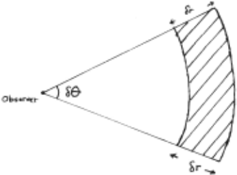
The nunher of targets seen in a given sonar .scan is variable and because of specularity and the relative movement of observer and target a given target will in general be seen only intermittently. The geometric measurements obtained for each tar get , in polar coordinates, are subject to errors of constant variance . llo11ever, when transformed into Cartesian coordinates the errors are range depen dent -- the voluue of uncertainty in lvhich the tar get lies is a sector with IVidth dependent on the sona r beam-width and thickness dependent on the sonar range resolution (see Figure 1). The e rrors are independent in polar coordinates but are cou pled, depending on the bearing, in Cartesian coor dinates.
I I. A HETi!OD FOR HOTION RESOLUTIO!I .
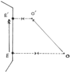
An alternative and more uniform definition of motion r esolution may be formulated in terms of target tracking. If the proper motions of all tar gets , including the sonar transducer as a special case target that is never seen, are tracked a glo bal frame may be established using the tracking data . Implicitly it is the frame with respect to which the transducer is tracked; explicitly, it is that frame in which stationary targets are fixed . In fact, although it is knmm lvhether a target is absolutely stationary, only the relative motion of the target with respect to the observer may be measured; and further, a stationary target does not imply a fixed absolute position (consider the sta tionary line re f lector in Figure 2, which mirrors obse rver motion parallel to the line). This motivates the fundamental insight of the method: if the relative t.IOtion of targets is tracked the observer movenent will appear as a common component of those relative motions, that may be extracted and tracked to derive the observer motion.
The basic block of the tracking system is the Kalman filter . Devised by R. E. Kalman [Kal60], this filter is a general and powerful recursive data processor . It is able to deal with input data vectors with variable error covariance and variable inter-sample times. For data with a unimodal error d i '> tri but ion with zero nean the Kalman filter is optimal in the sense that its estimates and predic tions of tracked quantities have minimal error variance, and the filter conputes error covariance matrices for its outputs in the course of its operation. The filter has been used extensively in radar tracking applications (for example, llorley and IHlsdon's multiradar tracking systen [rtor77]) though in these cases there is no observer motion to extract. It is conput ationnlly det1anding in general , hut can be simplified considerably in par ticular cases.
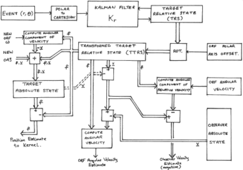
The notion resolution alp,orithn t~ay be divided into two parts: a set of per-target ~hannels (Fig ure 3); and a kernel (Figure 4). The kernel tracks the observer, which ha s three degrees of freedon - two translational and one rotational. Transla tional tracking naintains the global frame origin position while rotational tracking compensates for fluctuations in the vehicle's heading which shift the sonar transducer's polar origin. The kernel receives inputs from all active channels and may incorporate navigational data frot~ the vehicle's control system if available .
Each channel tracks a given target and is activated when that target is seen . Targets, for the purpose of tracking, are considered to be points and so have two degrees of freedom. The channel contains both relative and absolute motion data for its target and mechanisms to pass certain data to the kernel . ' \lith this o rganisation new targets are accommodated by creati ng a new channel, while defunct targets are eliminated hy destroying the associated channel.
Tracking is done in Cartesian coordinates. The kernel tracking is done with respect to the global reference frame; channels track their tar ge ts using coordinates in the observer relative frame. This latter frame is defined as the Cartesian reference frar~e with origin position of the sonar transducer and aligned with the azil'luth axis of the at the c urrent with x axis transducer.
The algorithn is cyclic in its operation; each cycle is initiated by target observation vectors (event vectors) arriving at their appropriate chan nels (the implied segmentation problen is discussed later). \lith reference to Figure 3, an arriving eve nt vector is transformed into Cartesian coordi nates in the observer relative frane (ORF), an error covariance natrix is conputed for it, an<i it is used as input to up<iate the target relative state (TRS) vector using the l:alman filter Kr. This state is a four conponent vector of position and velocity in the ORF. The TRS is rotated so that the OKF and global frat~e polar axes are alip,ne<i, and three quantities couputed fron this transformed THS (TTKS) provide kernel inputs .
- i). the target absolute position less the TTKS position is use d as an observer position estimate;
- ii) . the TT~S velocity, adjusted for the current ORF angular velocity estimate (and for tar get absolute motion), is used as an observer linear velocity estimate.
- iii). the T'rRS velocity is corrected using the current obse rver absolut e velocity, and for target absolute notion if necessary, and used to conpute an estinate of the obse rver (or OKF) angular velo city. These three estimates dr ive the kernel translational and rotational tracking .
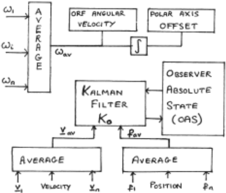
Figure 4: 1:e rrtel Pr ocessing.
The next phase of ac t ivity takes p l ace in the ke r nel (Fig ure 4) . Input s f r on al l active channels are collated , an<l conbined usi ng a non-recursive rninimam variance averagi ng fi lt er . Th i s filter is designed to have un i t cannon <'lOde gain while rejecting uncorrelated dif f e r e n tial inputs as nuch as possible, and is defined by t he equations below:
, - -1 X= p h p :X.i. .. ~
x. · ..
7he position and velocity data are tracked by the Kalnan filter, l:o, which naintains the four com ponf'nt observer absolute state (OAS) vector. The angular velocity average is used directly as the new OJU' angular velocity and the polar axis align te1ent is conputecl hy integrating the anr,ular velo city est iJ"late.
In the third phase of each cycle the kernel pn,;,;es the new estinate of the OAS to each active channel ~<hich adds the OAC. to the TTRS to conpute a ne1-1 estinate of its absolute state vector. Each estimated quantity passed throueh the systel'l is acconpanied by an appropriate variance or covari ance.
II I. L'lPUT SEGt1£NTATION.
As noted above, there is an implicit segmenta tion problen in matching target observation events to the appropriate channels. This is dealt with by using the prediction ability of the Kalnan filters in the channels. For each arrivine event the set of potentially natching channels is enunerated and a predicted TRS is conputed for each channel in the set. The potential match set is then pruned as foll01.Js. First, estimates of the radial and angu lar distances between the event and TKS are nade and conpared, all01-1ing for an unkn01m observer rotation, 11ith estimates of the corresponding vari ances. 11atches 1-1ith distances that are too large are rejected at once. Secondly, the filter innova tion distance (the distance between the TKS and event using the filter covariance matrix as a netric ) is conputed for each natch. The matches are classified into 'good' if the distance is less than 3. 5 standard deviations, or 'poor' if less than nine. t·latches nissing the poor' threshold are discarded. Thirdly, poor 10enbers of multiple natch classes that contain a eood toatch are elin inated. Lastly, the retaaining matches are inple nented: uniquely matched events are passed to their channels; u!ll~atched events 'initialise new channels; multiple good natches of events are dealt with by a nultiple target correlation schene (developed by Fortmann et al. [For80], and to be implemented slmrtly); multiple poor matches are deferred pend ing further data.
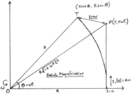
A problet:J that particularly affects segmenta tion arises froto allowing the ORF to rotate. The rotation of the ORF appears as connon angular velo city in the channel relative tracking filters. l!o~<ever, because these filters have a linear pred iction nodel, an error arises in the TKS due solely to polar origin shift. This is illustrated in fig ure 5. If the filter state is not estinated for a time t, the state will he predicted at point P, r(1,1.Jt) where w is the angular velocity. However, the actual position of the target is point T, r(cos 1-1t ,sin wt). The prediction error is roughly proportional to r(wt)~ , and must be corrected if this is large. This error also affects the angular velocity estimates conputed by the target channels, since the position estimate in each TKS will be displaced radially outwards relative to the correct position. The error is proportional to the rela tive distance between observer and target, and correction is nade for it in the angular velocity estimator.
IV. RESULTS.
The nethod has been tested using sinulated events generated by a nodeller progran. The nodeller reads initial values for target and observer position and velocity, and predicts their positions at future times. Each simulated sighting of a target causes an event vector to be generated . The nodeller can nove targets and observer deter ninistically, randonly, or in a combination of both nodes of movenent, and adds neasurenent error into the conputed vectors if desired. The randon nove nent and polar measurenent errors have Gaussian distribution.
Two sets of tests were run. In the first set the angular conpensation part of the taotion resolu tion system 1-1as turned off and the observer res tricted to translational notion only. The test ~<orld contained four objects positioned at the corners of a 70n sided square, centred on the ori gin, and the sonar scan repetition rate was 2.5Hz, corresponding to a range limit of :JOOu. Sinula tions ran fron one hundred to one thousand seconds of simulated time. Extensive error data were logged during the runs and the results of four of the tests are reproduced in tables one and two. In the second set, the angular coupensation system ~<as turned on, and tests run for about thirty seconds simulated time, using the same world uodel as the first set of tests. The sonar scan rate renained 2 · . 5Hz and the angular measuretoent standard devia tion ~<as 0.01 radians (about 0.57 degrees). In each test the radial l'leasurement error standard deviation was 0.01 metres (corresponding to a sonar range resolution of about 40cm).
Table 1 gives the error variance ranges for the four runs in series one. These figures were conputed by conparing the filter states with the rtodeller states after each cycle of the algorithn, accunulating the errors in the input measurenents, the TKS position, the target global state for each target and the observer global statF>. The vari ances pres<~nted are the naximun and minimun in each ca t egnry . Note that they are not the da ta vari ances couputed by the J~alman filters -- the filters 11ere unifon1ly r:10re pessimistic about the validity of their es timat es .
| lEST | CONDITIONS. | M~••"''c.."'"t v .... ~..u.. | -rRs Pcrli*"l•fl V-.r~~"'c~ | �-lo~o.L Poti.+\oll\ '1/.r.:.-...c.~ | G-loboo.L Vtlocil-y Vo.~«. | OI'IS Ptrih"• \1-.,.~0E.. | OAS "•'·...:~ \14t.~C:<. |
|---|---|---|---|---|---|---|---|
| 1a. | Olosuv<!.r VdoC..:f:j Co.o6; o. oa-) ObJ'ec.ts ~1:~""'"'"1· ,..,..e ~c:o | 12. | 1.3 | 1.8" | o . .:z. | O.<t-5 | O. II |
| : 100 ... cfs . e sm .. ~ ekvc"tt~· .. -1 O.l,.,.d OloSCN<'r VQloC...:~ Co.o,, o.o8) -r..,. Objec.l-1 M<>V~"5 : (o. 3S", o.2) (o, o. n,..,. ·. 100 sec:<>o'\C.S. | 10 0.1'1- | o.'f o.OI'I | o. S" | " · 0\f- | 11.'+" | o.oB 7. 1c-3 | |
| ib | '-) sfru,..J.<,..,.cl *"..o.t.·, .. e 0 . 01 ......... | o.ol.O | o.oo3 | 0.11.8 o.o~ | He-3 l.'k-l | 0 . 110 O.Olf-11 | l.fe-3 |
| 1c | Ol.$(..,..oJU V~LoC...:~ (o. o,, o.M) -+ .... M. .. Oloj.o.c.\-1' sh>.+-c..,.._~ T1'i'\e: 2._00 '""'""""'~ e ~dtu-J .kv<~t.+.:""' 0 . 01 "''* | o.lf.S'O 0 .002 | 0 .04.0 O.OO'f. | o.11.o o. on. | ~.s-c-S 1.0<!.-S' | 3 1.~ | 1.6e-~ l.l .. -lf. |
| .iJ | As ic:, wttl... -r,:.. ... \000 ~u..JJ R.._,..J,,., poo.:n:o,. .forc..o. 0 .04"' ..;. -" c:U.if\-tM'St.:0\1\ ~ ... ~m \e.,,.,~. | o. l%0 0 . 11!-0 | o.o~to'f 0.0\0 | O.ISO O.OS"t,. | 1. ~ .. -'+- 3.2."-' | 0.1>00 o.t1o | 1 .'l.e-S' 2...'h-5 |
| frul | Obse~r- | l<t"3~t: :1.. | 'T~et 2. | T~ec ~ | T~e.t- l.r | |||||
|---|---|---|---|---|---|---|---|---|---|---|
| )( | ;! | X | '::! | )( | j | )( | ':i | >< | '::l | |
| i ... | 3.s | -0.(:, | 2 . 'l | -0.1 | 4.~ | -0.2.. I | 2.=1- | -\.I ! | 4-.t | -0·3 |
| d.b | 1.!1. | l.q | I. I | 1.9 | 1.'!. | I l.'l | l.'l | I 2..0 | (. 2. | 2.0 |
| :/..<. | '30. 0 | 3,.~ | 1-~ . 'l | ~ .'1 | ~0. 0 | '3'\.11 | lO.O | 'l'l.:r | '30. 0 | '11. '1 |
| 1J | 30. C. | 4L>.2.. | ?.o. S' | 4-0. 1 | '30.C. | 3'\., | 1,0. 3 | ~1 . 1 | 30.C. | 4-f>.O |
Table 2 shows the coo rdinate origin offset vectors for the te s ts. These values are difference between the targe t and observer absolute positions and tl~ corresponding data in the nodeller s tates. The sizes of these nunbe rs depends upon the differ e nce between the modeller's initia l position for the observer and the notion resolution system's s tarting observer position of (0 ,0), and on the amount of drift of the g lobal fr ame origin whi ch occurs during the initialisation period o f the filter sys ten. The stability of the global frane of refere nce in each test is indi ca ted by the simi larity between co rresponding displacer.1ents for dif fe rent targets a nd observer. No t e that test ld is a l eng thi e r run of test lc, so that conparison bet\Jeen these ro11s of '::able 2 sl>OI<s the time sta bili t y of the g l oba l frame; conparison I·Jithin the ro11s· sho11s the spatial stability of the frame.
Table 3 shows the observer absolute state variances and the biases in the ant;ular state con ponents for each of tlu~ t<~sts in series two. These fig ur es a re the r.1eans and variances of the differ e nces between system conputed ~uantities and modeller generated quantities, as in Table I. Tab le 4 s hows the coordinate ori g in offset vectors fo r tests 2a and 2b. Results of this nature for tests 2c a nd 2<1 are not meaningful because of the l a r ge values of the polar axis bias in those tests. The values in Tables 3 and 4 are inherently less reliable than those in Tables 1 and 2 because of the sma lle r nunber of saraples involve d ( sm1e seve nty as against two hundred and forty).
V COtlCLIJSIOflS.
- 1). The systen perfonns 1<ell when presented with data containing only translational motion. It r eject s object motion satisfactorily and maintains a stable frame of reference under extrene input e rror conditions-- the standard deviation of 0.1 r adians in test la corresponds to a sonar beam width of more than ten degrees. The reference frame is stable over long periods of time, its ori gin drifting about 60cm in 800 seconds, and the movenent of thP. observer with respect to the refer e nce frame. is trackP.d correctly. Thus unde r these conditions the systen fulfils its goal of impli ci tly defining a stable stationary frame of refer ence .
- 2). When presented with data containing rota tional error the system perfon~s poorly. The cause of failure is the consistent lo~< estimate of the ORF an[\ular velocity (101~ by 3.8 milliradians per second in tests 2c,d) which integrates over the test period to account for half of the bias in the polar axis offset (filter initialisation time accounts for the other half). This gradual drift in the polar axis offset causes the global frame to rotate and interferes severely with absolute
position and velocity extrac tion (thus there are no offset result s for these tests). The erro r appears to be independent of the observer linear motion since it i s seen ident i call y in the r esults of test s 2c and 2d . Further t es ting "il l sho\1 lJhP.ther the angular ve locity deficit is Jue t o a biassed e st imato r or is a further rotational non-linearity e rror of the t ype a lrearly descrined.
- J). It re~uires between five and ten activa tions of a give n c hanne l t" initialise the relative tracki ng filter s uccessfull y . Since the g l obal reference frame ca n be es tablished usinc onl y four targets the sys ten will cope \Jith in te rmitt e nt sightings of t arge ts easi l y . For a s onar scan r ate of 2.)1!z it may take up to abou t thi rt y seconds to collect the necessary obse rvations (assw1ing a ve r y pessimistic rate of appearance for the targets); with nore sophisticated sonar systetos it will take only a few seconds .
- 4). \.Jhil e the sys tem is c urr.,ntly inade~uate for na rine vehicles, ~>ere ant;ular effects c annot be eliminated easi ly, it is suitable fo r use in land based ve hic les. The structure of the syste1· allows it to incorporate pos itio n o r velocity data fron o ther sour ces into the kerne l averaging pro cess. Thus mechanically obtained es tinat es of the mo tion of a r obot veh icle could be used to improve the se ttling time of the g l obal franc and increase the stability of the obse rve r tracking further. i he long term and spatial stability of the refe r ence fra~ae make it usef ul for naviga tion . The nodifications necessary to enable the systera to cope with narine conditions lvi ll be done in further work whe n the cause of the l ow a ngul a r velocity estimate has been fully investigated.
REFCRENCES .
.E!l.r.liQ Forttoann Tl: , Bar-Shalon Y, 1930, '!lultitarget tracking usinr; joint tic data association'; 11:r:E llecision 1930,2, p807. Schef fe 11 , proba bilis & Cont rol
~ Kalman RF., 1960, 'A new appr oac h to linea r filtering and prediction problet.Js '; Tr a ns ASHE Journal of Basic Engineering l·!.c'l r c h 1960 pp35-45.
l·!or80 :loravec 1!1', 1980 , 'Obstac l e avoidance a nd naviga tion in the r eal world by a seeing robot rover'; Stanford Artificial Intelligence Laboratory llerao AIH- 340.
Hor77 aorley AR & I.Jilsdon AS , 1977, tracki nG in a multisite e nvironme nt'; International Conference, p66. 'Hul t i r ada r RADAR-77 10:
| Tl:S"!" | C.ONPo-rooNS | f'o!M Ale:l'S olt ... t: e .... | B\c:u VAr~~ | o~F~.._t..,. VtloC.:'-j t..:..S | Bi.u v~nQ.Aol\c~ | OlosUol<r Ats~'"'-·-.. V..r. | O'c>s~NU" "·~\lor. |
|---|---|---|---|---|---|---|---|
| 2A | Ob)Uolr S+z,.+-:c~ ... "1 QO,jc.e!·~ Sh..+-.C.. .... '"'j e~..~.~~ ..... o.ol""' .-,· ""~ : '30 )tto"'J~ | 1.3t.c-1 | 1.35e-G. | 5.He-5 | '--l"t.,-1 | !>.ooc-s | I r.ro~-~ |
| 26 | ObSUVOOA" Mo"..J..'l (o.o8, 0 . 04) O'c>j~<h S'too..~ e ~J.,..,-cl olt_v.AI--.'<M 0.01~ T,-....<!. : '30 ~CcN<ch | -2.0/,1!- :> | t.Me-G. | '5".-:tS"e-S | :u."'lc-'1- | 4.2.4-C -S | 'l.'ltc-l. |
| !l..c | OloJe.r~er ,..,w,.· ... 'j O.OS" rwol/' ~bj'ec-" m...~ ,~v,~- 0.01 .....I e ~ T,· ..... e : '30 '~""''h | - 0,2.00 | 7.0'1 ~-4- | -3.~0e-3 | '\.11 C-b | l.fb'c-3 | ~ .'il+t-S |
| 2.:l | 1--- O"o,e.<"vt.r f.llov""'~ (o.ot, o.o&) ~ ,.,n.t-.: .. , o.oS' ...J.Is 0\ojecl-1 ,t..,-h"""""'"'j. e .......... .w-cJ. c:~_-v...h.;,..., 0.01 ,....I -n ... e: '30 ... CQ-A).. | - o.UJo | "1.'2.S"e-lj. | -3.'~4-c-3 | &>.e.rc-t:. | 1 • .2.2. | 3.'Ht-3 |
| TEST | Oloser-.tu· | "T~ef: ~ | T"""'l« 2 | ~ ... ~- 3 | T9ct. 4- | |||||
|---|---|---|---|---|---|---|---|---|---|---|
| )( | ':! | X | ':I | )( | ':1 | " | 'j | )( | ':1 | |
| :?_A | 104- | -4-11--~ | SS". '+ | 41-"' | 1~.1 | -II . '2... | -~2..$ | -102. | -'30."1 | -2.\t.O |
| .Zb | -\98 | -IS"t:. | -1'3€. | -10:2.. | -l'f<. | -IS"'\ | -2.1-14- | -2.4-S | -11.2 | -11-1 |
@inproceedings{ijcai1983p193,
  title     = {Resolving Observer Motion by Object Tracking},
  author    = {Hallam, John},
  booktitle = {Proceedings of the Eighth International Joint Conference on
               Artificial Intelligence, {IJCAI-83}},
  publisher = {International Joint Conferences on Artificial Intelligence},
  editor    = {Alan Bundy},
  pages     = {792--797},
  year      = {1983},
  note      = {Robotics},
  url       = {https://ijcai.org/proceedings/1983/193},
}
TY - CPAPER TI - Resolving Observer Motion by Object Tracking AU - Hallam, John T2 - Proceedings of the Eighth International Joint Conference on Artificial Intelligence, IJCAI-83 PB - International Joint Conferences on Artificial Intelligence PY - 1983 SP - 792 EP - 797 UR - https://ijcai.org/proceedings/1983/193 ER -Copied
Machine-readable versions of this paper, for tools and AI agents:





