
A Knowledge-Based Program Editor
Proceedings of the Seventh International Joint Conference on Artificial Intelligence. Programming Environments. Pages 920-925.
© 1981 International Joint Conferences on Artificial Intelligence
Abstract
This paper describes an initial implementation of an interactive programming as sistant system called the Programmer's Apprentice (PA). The PA . is designed to be midway between an improved programming methodology and an automatic programming system. The intention is that the progr amroer will do I he hard parts of design and implementat ion while the PA will assist him wherever poss ible. One of The major underpinnings of the PAis a representation (called a plan) for programs which abstracts away from the inessent i al feature s of a program, and represents the basic logical properties of the algor i thm explicitly. The current system is composed of four parts: an analyzer that can construct the plan for a program; a coder that can create program text corresponding to a plan; a library of plans lor common algorithmic fragments; and a plan editor which mal<.es it possible for a programmer to modify a program by modifying its plan. The greatest lever age provided by I he system comes from the fact I hat a programmer can rapidly and accurately build up a program by referring to the fragments in the library and from the fact that the editor provides commands specifically designed to facilitate program modificat i on .
- R. Balzer, "Transformationallmplementetion: An Enmple", IEEE Trans. on Software Eng., V7 •1, January, 1981.
- D.R. Barstow, "Automatic Construction of Alaorithms and Data Structures Using A Knowledge Base of Proarammin& Rules", Stanford AIM-308, Nov. 1977.
- D.C. Brotsky, "Proaram Understandin& Through Cliche Recognition", MIT masters thesis proposal, March 1981.
- T.E. Cheatham, "An Overview of the Harvard Program Development System", pp. 253-266 in "Software Engineering Environments• H. Hunke ed., North-Holland, 1981.
- V. Donzeau-Gouge, et at, "A Structure-Qriented Program Editor; A First Step Towards Computer Assisted Prognmmina•, Proc. Int. COmputing Symp., Antibes, 1975.
- L.J. Guibas and O.K. Wyatt, "Compilation and Delayed Evaluation in APL •, Proceedings of 5th ACM POPL Conference, 1978.
- P. Feiler and R. Medina-Mora, "An Incremental Programming Environment", proc. of the 5th Int. Coni. on Soft. Eng., San Diego CA, March 1981.
- C. Rich, "Inspection Methods in Programmina•, MIT /AI/TR-604, (based on an MIT PhD. thesis June 1980), to appear.
- C. Rich, "A Lenguage-independent Representation for Standard Program Forms", I.JCAI-81, August 1981.
- C. Rich and H. Shrobe, "Initial Report on a Lisp Programmer's Apprentice", MIT/AI/TR-354, MIT Cambridge MA, December 1976.
- C. Rich and H. Shrobe, "Initial Report on a Lisp Programmer's Apprentice", IEEE Trans. on Soft. Ena., V4 16, November 1978, pp. 456-467.
- T. Teillebaum, "The Cornell Program Synthesizer", Tech. Rep. 79-370, Dept. of Computer Science, Cornell Univ., 1979.
- R.C. Waters, "A System for Understandin& Mathemetical FORTRAN Programs", MIT /AIM-368, MIT Cembridge MA, August 1976.
- R.C. Waters, "Automatic Analysis of the Loaicel Structure of Programs", MIT/AI/TR-492, (Based on an MIT PhD. Thesis August 1978), December 1978.
- R.C. Waters, "A Method for Analyzing Loop Proarams", IEEE Trans. on Software Ena. V5 •3, May 1979.
References were extracted automatically from the PDF and may contain errors.
Full text extracted automatically from the PDF; figures, tables and equations may differ. The PDF is the version of record.
I. Introduction
The Programmer's Apprentice (PA) is an interactive system for assisting programmers with the task of programming. It is intended to act as a junior partner and critic, keeping lr ack of del ails and assishng . in the documentation, verif ication, debugging, and mod1focat10n of a program while the programmer does the hard pari~ of design and implementat ion. In order to cooperate with a programmer, the PA must be able to understand what is going on. From the point of view of artificial intelligence, one of the central developments of the Programmer's Apprentice project has been the design of a representation (called a p/1n) for programs and for knowledge about programming which serves as the basis for this understanding.
Rich and Shrobe [IO,II]Iaid out the initial design for the PA and for plans (see Section Ill). The author [13] designed a limited system intended to operate in the domain of mathematical FORTRAN programs and extended the idea of a plan by developing a theory of how plans could be segmented [14,15] (see Section IV). IIAore recently Rich [8,9) has further developed the plan formalism (see Section IX) and designed a library of plans representing many of the standard cl iches in non-numerical programming.
This report describes research done at the Artificial Intelligence Laboratory of the Massachusetts Institute of Technology. Support ~or I he labor a lory's artificial intelligence research has been provided '" part by the Advanced Research Projects Agency of the Department of Defense under Office of Naval Research contracts NOOO 14-75-C-0643 and NOOO 14-80-C-0505, and in part by National Sc1ence Foundation grant MCS-7912179.
The views and conclusions contained in this paper are those of the author,. and should not be interpreted as necessarily representing the Off1c11l pohc1es, e1lher expressed or implied, of the Department of Defense, the National Science Foundation, or the United Slates Government.
Section II outlines the architecture of the system. The plan formalism which underlies the system is briefly discussed in Section Ill . Sections IV-VII describe the lour components of the system Section VIII gives a scenario ·or the use of the system. Section IX discusses the weaknesses of the current system, and how these problems will be addressed in the second implementation ol the PA which is now under way.
II. Outline of the Current System
The current system is composed of lour modules as shown in Figure I. Given the text for a piece of a program, the analyzer module can construct a plan corresponding to it. The coder module performs the reverse transformation, creating program text corresponding to a plan. The plan library contains common program fragments represented as plans. The plan editor makes it possible for the user to modify a program by modifying its plan.
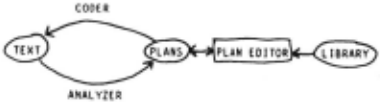
The system maintains two representations (program text and a plan) lor the program being worl<.ed on. If the programmer uses the plan editor to change the plan, then the system uses the coder to determine what the· new program text should be. If the programmer uses an ordinary text editor to change the program text, then the analyzer os used to determine what the resulting plan should be. It should be noted that the existence of the analyzer means thai the system can be used to modify programs that were not originally constructed using the system.
The leverage provided by the system comes primarily from two things. First, the programmer can rapidly and accurately build up a pr(lgram be referring to the fragments in the plan library. Second, the editor provides a variety of commands specifically designed to facilitate program modification.
There is a similarity between this system and a programming language syntax editor (such as Mentor [51 the Cornell program synthesizer [12], or Gandall [7]) in thai the user operates on an underlying representation lor the program rather than on its textual representation. In both cases many simple errors are prevented because it is no longer possible to even state them.
There are however three key differences between this system and a programming language syntax editor. First, this system does not depend on the syntax of any particular programming language. All of the operat ions of the system are performed on plans. Except lor parts of the coder and analyzer modules, the whole system is essentially programming language independent. Second, the existence of the plan library changes the character of the interaction. l'he only prototypes known to the typical syntax editor are ones related to the basic syntactic constructs of the language. Third, this system specifically supports non-local modifications such as sharing. The typical syntax editor only supports the addition and deletion of individual syntactic units.
There is also a similarity between the current system and a transformational program development system such as T1 [ 1), PSI [2) or PDS [ 4). The key similarity is that both approaches rely heavily on libraries of standard programming cliches. In a transformational system these are represented as transformations. In the PA these are represented as plans. However, there is a considerable difference in the approach to lhe way this knowledge is used.
In the transformational approach a program is first completely specified at an abstract level and then a translormalional component selects (more or less automatically) transformations (which are intended to be correctness preserving) in order to implement the program in an efficient way. There is, however, no support for creating or modifying the abstract specification itself. The current implementation of the PA is both more modest in its goals, and more flexible. A program does not have to be specified at an abstract level; there is no automatic selection of cliches to use; and the addition of a library cliche into a program is not expected to be a correctness preserving process. The PA is intended to support the programming process at all levels. Future implementations of the PA will include some automatic cliche selection and are intended to support the kind programming style pioneered by research on transformational systems, in addition to the interactive programming style presented here.
Ill. Plane
The importance of plans as the underlying representation used by the system cannot be overemphasized. The utility of the plan representation stems from the fact that it is specifically designed to make the kind of tasks performed -by the system easy to do. In order -to do this, the plan representation is designed to make all of the information the system needs to know explicit and local in a plan.
A plan is like a flow chart except that the data flow as well as the control flow is represented by explicit arcs. The basic unit of a plan is a segment. A segment corresponds to a unit of computation. It has a number of input ports and output ports which specify the input values it receives and the output values it produces. It has a set of specifications which give preconditions which must be true of the inputs in order lor the segment to execute properly, and postcondilions which describe what will be true after the segment is executed.
Control flow from one segment to another is represented by an explicit arc from the output side of the first segment to the input side of the second segment. Similarly, data flow from the output of one segment to the input of another is represented by an explicit arc from the appropriate output port of the first segment to the appropriate input port of the second segment.
In addition to segments corresponding to primitive computations there can be intermediate segments containing groups of inner segments. All. of the data flow between segments outside of an intermediate segment and segments inside an intermediate segment is channeled through input and output ports attached to the intermediate segment. All of the computation corresponding to a single subroutine will be grouped together into one outermost segment.
An important feature of the plan representation is that it abstracts away from inessential features of a program. Whenever possible il tries to eliminate features which stem from the way things must be expressed in a particular programming language, and keep only those features which are essential to the actual algorithm. For example, a plan does not represent a data flow in terms of the way it could be implemented in any particular programming language (e.g. with variables, or nesting of expressions, or parameter passing). Rather, it just records what the net data flow is. (For the convenience of the coder, a plan can have annotations which suggest what variable names are appropriate for a particular data flow.) Similarly, no information is represented about how control flow is implemented .. One result of this abstraction is that plans are much more canonical than program texl. Prog·ams which vary only in the way their control flow and data flow is implemented all correspond to the same plan.
Another important feature of the plan representation is that it tries to make things as local as possible. For example, each data flow arc represents a specific communication of data from one place to another and, by the definition of what a data flow arc is, the other data flow arcs in the plan cannot have any effect on this. The same is true for control flow arcs. This leads to the property of additivity It is always permissible to put two sections of a plan side by side· without their disturbing each other. If there is no data flow or control flow between the sections, then they can have no effect upon each other.
Additionally, intermediate segmentation breaks a plan up into regions which can be manipulated separately due to the fact that the plan representation is designed so thai nothing outside of a segment can depend on anything inside that segment . This leads to the property of substitutability. It is always permissible to replace any segment with another segment as long as the two are eKternally indistinguishable.
IV. The Analyzer
The analyzer (described in [15] and more fully in [ 14)) automatically produces a plan corresponding to a program. This is done in three steps: source translation, surface analysis, and segmentation. In the source translation step, a language specific module parses the program text and converts it into a Lisp-like intermediate form. Source translators currently exist for Fortran and lor Cobol. None is needed for Lisp.
The surface analyzer runs over the intermediate form like an evaluator creating a surface plan as it goes. A surface plan is composed solely of a large number of terminal segments corresponding to prirnilive operations (such as "+" and "·") grouped into one large segment and connected by data flow and control flow. The surface analyzer has detailed knowledge of the constructs which implement data flow and control flow. However, it does not have any knowledge of what the primitive functions do except how many inputs and outputs they .have.
A surface plan is flat in that it has no hierarchical structure. The segmentation step introduces intermediate segmentation reflecting the logical structure of the plan. The primary goal of this process is to group segments which interact heavily close together, and keep segments which interact little, if at all, far apart. The segmentation is done in terms of six basic configurations called plan building methods (PflMs). It proceeds bottom up based on the topology of the control flow and data flow by locating minimal configurations which can be grouped together inside intermediate segments in accordance with the PBMs.
In general, the PBMs correspond to basic structured programmin& constructs: expressions, complex predicates, conditional expressions, and loops. The primary innovative feature is that loops are analyzed as compositions of fragments of looping behavior communicating by means of temporal sequences (streams) of values, rather than as repetitively executed pieces of straight-line code. For example, the loop in Figure 2 would be analyzed as a composition of four loop fragments as shown in Figure 3.
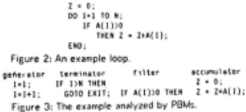
The first fragment (a generator) counts up by I !rem I creating an unbounded temporal sequence of values { 1,2, ... }. The second fragment (a terminator) tests the sequence of integers produced by the generator and slops the loop when an integer greater than N is found. This has the effect of truncating the sequence of integers to the sequence {1,2, ... N}. (Both of these fragments are part of the DO construct.) The third fragment (a filter) restricts the truncated sequence of integers by selecting only those integers which correspond to positive elements of the vector A. The last fragment (an accumulator) computes the sum of the elements of A corresponding to the integers in the restricted sequence produced by the filter . In the loop as a whole, the four fragments are cascaded together so that the loop computes the sum of the positive members of the first N elements of A.
From the point of view of the system being described here, this analysis is Important because it provides very convenient intermediate segmentation. For example, if the programmer wanted to change the loop 1bove into one which computed the product of all of the elements in the vector, he would only have to remove the filler, and replace I he summation accumulator with a product accumulator.
V. The Coder
The coder I akes in a segmented plan and creates the code for a Lisp program corresponding to it. This process is relatively straightforward. The structure of the program produced closely follows the structure of the seemented plan. In general, each terminal segment in the plan is implemented as 1 function call, and each non-terminal segment in the plan is implemented using a syntactic construct corresponding to its PBM For ex1mple, a segment whose PBM is conditional will usually be coded using a COND. There are only two areas of real difficulty: determining how to implement the dal1 flow in the pl1n, and duling with loops.
The data flow is 1 problem because the plan formalism deliberately does not represent much information about how dal a flow should be implemented. The coder is forced to discover how to use variables and nesting of function tills in order to implement the required data flow. In order to gel mnemonic variable names, the plan contains explicit suggestions for what variable names to use when variables are required.
When deciding how to implement the d1la flow in 1 plan, the coder first identifies every place where the nesting of function calls can be used. It then identifies related groups of data flow arcs thai can be implemented using the same variable. Its basic goal is to use the smallest number of variables possible. When picking names for these variables, it uses any suggestions recorded in the plan. It has to be particularly careful to make sure that there is no conflict when the same name is suggested for two different groups of dal a flow arcs.
In order to produce Lisp code for a loop analyzed as a composition of loop fragments, the fragments must first be combined together into a single loop. This process (see [14)) is designed so that the validity of the simple logical analysis in terms of composition will be preserved. The fragments are taken apart, and their pieces are reassembled into the resulting loop. The arrangement of the pieces in the loop is dictated by the data flow communicating temporal sequences of values between the fragments. The key idea is that if a piece of one fragment uses a temporal sequence created by a piece of another fragment, then the consuming piece should be placed after the producing piece in the resulting loop. The action of 1 filler is produced by placing the pieces which receive its outputs within the scope of 1 conditional prediceled on the filter's lest. Similar problems h1ve been attacked by the people working on compilers for APL (see for example, [6 )).
Vl . The Pt1n librtry
The plan library is a collection of plans for common algorithmic fragments. There are fragments corresponding to the six PBMs (e.g. conditional, predicate, loop, etc.). In addition, there are a variety of more specific programming cliches such as those in Figure 3 (i.e. counting up, slopping at a given number, selecting out the positive elements, and summing up). It should be noted that this is more useful than a collection of fragments represented in a programming language for three reasons. First, the plan fragments are more canonical. A given plan can be realized as code in many different ways. Second, many fragments ere so fragmentary the! they do not correspond to any syntactically reasonable section of code. Third, due to the additivity properly of pl1ns, having the fragments represented as plans makes it easier to combine them. The system does not have to worry about issues like variable name conflicts, because there are no variables.
The library makes two basic things available to the user. First, he can include a fragment in the program he is constructing by referring to it by name (e.g. "conditional", "count", "summ1lion", etc.). Second, each fr agmenl has named paris some of which may be unspecified. For example, a conditional has some unspecified lest, a summation has an "accumulation" part which is specified to be +, and it has a sequence part (the temporal sequence to De summeOJ wnocn os unspecified. When a fragment is instantiated its part names are carried over as well. The programmer can then use them when referring to the program he is constructing (e.g. "test of conditionar, "accumulation of summation", "sequence of summation").
VII . The Plan Editor
The plan editor provides a set of commands which a proer am mer can use to modify the program he is working on, by modifying its plan. He communicates with the plan editor using an Lll pseudo English. The central feature of the system is the vocabulary that the programmer uses. The semantics of this vocabulary is based on the plan notation and the plan fragments in the library.
The basic objects known to the system are the objects in a plan: segments, input and output ports of segments, data flow, and control flow. Various adjectives are available for referring to particular kinds of objects. For example, "constant segment", "function call segment", "first segment", "free variable input", or "side-effect output". Pari name expressions refer to the relationships between objects. For example, "subsegment of segment", "input of segment", "use of output", or "source of data flow". As discussed above, the fragments in the plan library and their parts can be referred to by name.
A programmer can refer to a specific part of the plan for the program he is working on by using the word "the" (e.g. "The test of the program Foo"). Complex references can be built up by nesting simple ones (e.g. "the use of the side-effect output of the action of the program FOO"). These phrases make it possible for the programmer to treat his program as ari algorithmic structure, rather than a syntactic one. He can identify parts of the program based on their role in the algorithm, rather than based on their location in the text, or by their relationship to the parse tree for the program, as in a programming language structure editor. As a convenient method of reference, the pronoun "it" is used to refer to the object which is the current focus of the system's attention. In addition, program names and variable names can be used to refer to the associated objects.
The word "a" is used to create an instance of something. For example, "a summation", or "a side-effected free variable output TBL ". The programmer can also use literal pieces of program text (such as '(oq (cor current) ''"'bo1)) in order to create a new fragment of plan. <The analyzer is used to convert the text into a plan.)
The editor provides a variety of verbs which specify actions to be performed. Two of these: "define" (a new program) and "implement" (an unspecified part a plan fragment), are used to build up a program by combining prototypes from the library. As this is being done, the system annotates the resulting plan so that it embodies an analysis of the program in terms of the fragments used to create it.
Another group of commands (such as "add" (some object to the plan), "remove~ (some object from the plan), "replace" (some object with another), "share" (two segments together as 1 single instance), etc.) are used to modify a plan. The primary leverage here is that it is much easier to make changes to a plan without causing unwanted side-effects, than it is to make changes to program text. without causing unwanted side-effects. This is due to the fact that in a plan things are represented explicitly, locally, and irredundantly so. that in general if some feature of the plan is changed, it doesn't effect any other feature of the plan. In contrast consider the use of variables in a programming language. Using a variable to implement a data flow in one place can have arbitrary effects on other data flows that happen to be implemented using the same variable.
Note that the process of modification interacts strongly with the process of constructing a plan from prototypical fragments. As mentioned above, the plan embodoes an analysis of the program in terms of the fragments used to create it. Once an orthogonal modification is made to the program, it must be reanalyzed in order to determine what fragments correspond to its new structure. Whenever possible this reanalysis is done incrementally so that only the immediate neighborhood of the change is effected. If complete reanalysis is required, then information about the specific library cliches used to build up the plan is lost due to the I act that the current analyzer can only analyze a program in terms of the PBMs.
The plan editor also makes available several commands for displaying information to the programmer. For example, he can ask what parts of the plan are still incomplete, he can ask the system to describe parts of the plan, or he can ask the system to display the parts of the program which correspond to a part of the plan.
VIII. A Scenario
This section presents a brief scenario showing an actual interaction with the current system. The programmer is constructing' a function DElETE which will delete (by side-effect) an occurrence of a symbol from a set implemented as 1 hash table. As shown in Figure 4, the hash table is a vector of lists (called buckets). Each symbol in the set is placed in one of the buckets. In order to simplify the deletion process, the hash table is implemented using buckets which have special header cells of H ll.
The set (ABC 0 E f G HI J L H N) is stored as :
[(NIL A E I H)
(NIL B F J H)
(NIL C G)
;NIL 0 H L)]
Figure 4: An example of the hash table.
The programmer has already coded the function in Figure 5 which I akes in a· symbol, and returns the appropriate bucket of the hash table. The function works by generating a unique number corresponding to the symbol, laking the remainder of this number alter dividing by the size of the hble, and then using this remainder to index into the table. Note that the hash table itself (TBL) as well as Its size ( TBLS 1 ZE) are free variables.
(OEF JNE HASH (SYMBOL) (ARRAYFETCH TBL (REMAINDER (HAKNUH SYMBOL) TBLSIZE))) Figure 5: The hashing program.
The programmer communicates with the system by typing at a video terminal. The screen of !lie terminal is divided into two regions (see Frame 1). The top region shows what the programmer types. The lower region is used by the system to display code for the program being worked on. The pari of the program that the system's attention is focused on (it) is highlighted on the display (this is indicated by underlining in the figures below). The last line of the lower region is a part expression identifying the highlighted section. E1ch frame in this scenario corresponds to · screen image seen by the programmer.
The first frame shows the programmer starling to build up his program by combining fragments from the library. First, he begins the definition of l~e function, specifying its parameter. He then implements the pr011.ram as a lrailing-poinler-list-enumeralion.
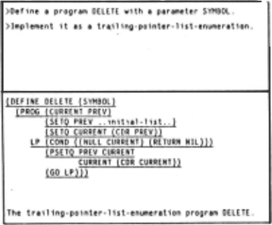
The reader might well complain at this point that "trailing-poinler lisl-enumer a! ion" is a very cumbersome name and that no one would want to have to remember it or use it. There are several points to be made. First, the actual name itself is not important. What : ~ important is that the process of moving a pointer (here CURRENT) down a list starling at the second element whiiP. maintaining a second
(lrailin~) pointer (here PREY) pointing to the preceding list element (see Figure 6) is a common algorithm that is known both to programmers and to the system. Second, there has to be some way to refer to it so that the programmer can pull it into his program when he wants it. Just as in lnlerlisp a prosrammer has to know the names of the functions in the manual in order to use them, the user of this system has to know the names of the prototypes in the library. Third, Section IX shows how the next implementation of the PA will reduce. the need for the programmer to know idiosyncratic names like this.

The tower part of Frame I shows the code produced by the coder Dased on the plan constructed by the user's commands. The coder uses a PSETQ (parallel assignment) in the code it produces because that is easier than trying to figure out what order the assignments should be done in. The plan, and therefore the code, is fragmentary because the programmer's description of the program so far is fragmentary. The coder is specifically designed so that it will produce legible (though perhaps not runnable) code for a plan no matter how fragmentary !he plan is. The code in the display serves as a summary of what has gone em so far in the editing session. The symbol " .. 1n1thl-lht .. " is used to represent the, so far unspecified, initial-list part of the trailing-pointer-list-enumeration fragment.
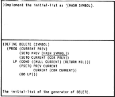
. In Frame ~· the programmer fills in the initial-list slot by Implementing 11. IS the expression "(HASH SYMBOL)". Through the ab11ily to pull 1n fragments from the library, and then fill in their unspecified parts with pieces of code, or other fragments from the library, the system supports the lop down construction of a program.
Frame Z
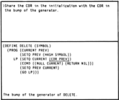
The next two frames illustrate a completely different mode of interaction with the system: modification. Typically program construction (and certainly debugging) involves a lot of modif ication as the program evolves into an acceptable implementation. In Frame 3 the user has decided that he doesn't like the algorithm for trailing pointer list enumeration used by the system because it contains an unnecessary instance of COR. He asks the system to get rid of this by sharing the two instances of COR. This is a good example of a modification which is easy to slate, but which is not so easy. to perform on program text. The main problem is that looking simply at the text, it is not easy to lett whether or not the sharing is possible. The whole program must be checked to see that there are no side-effects or modifications of the variables involved which prevent the sharing. The system gels considerable leverage on this be, ~use these questions are easy to answer in the plan representation due to the fact that all of the data flow is represented as explicit arcs.
Once it has been determined that the sharing is permissible, relatively global changes may have to be made in the code. For example, a temporary variable may have to be introduced. Here things are particularly complicated due to the fact that the COR in the loop has to be shifted around to the top of the loop before it can be· shared with the coR in the initialization. Here again the required tasks are easier to perform on a plan than on program text . The coder is used to create the new text after the .plan is modified.
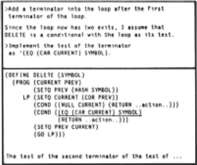
In Frame 4 the programmer adds a second terminator into the loop. This causes the loop to have two exits. The system responds to this by embedding the loop as the lest of a conditional. This reflects the assumption that the programmer intends to perform separate (unspecified) actions corresponding to the two loop terminations (otherwise· he would have combined them into one termination with a compound lest), and that he intends to join the control flow after these two distinct actions, and simply return from the funct ion in either case. The system notifies the user of this change because it is a somewhat non-obvious one, and because it changes the way things can be referred to by adding an additional level of nesting into the plan.
The second programmer request in Frame 4 specifies the test of the additional terminator. The test slops the loop if an element identical to the input symbol is found. Note that the programmer simply gave a little piece of code because that was easier than specifying what he wanted any other way.
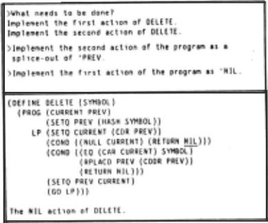
At this point, in order to demonstrate another capability of the current system, the programmer asks what needs to be done (see Frame 5). The system keeps track of all of the aspects of the plan which are incomplete. It replies that the two actions still need to be implemented. The programmer then specifies these actions. Note that he refers to the simple programming cliche "splice-out".
The last frame demonstrates some other capabilities of 'he current system. In response to the request "describe", the system can report out simple features of the plan. Here, the programmer asks for a description of the inputs and outputs of the program. Note that the system has figured out that TIL and TBLS IZE are free variable inouls to DELETE since lhev are free variable inputs to HASH.
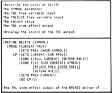
More interestingly, the system realizes that TBL is also an output of DELETE. The system deduces this, even though it is not at all obvious from the way the programmer built the program up, becau5e it has a simple model of side-effects which allows it to understand many common situations where side-effects are used. It knows thai if a program side-effects some part of a structure, then the structure as a whole is also side-effected. Here, the APLACO potentially changes PREV which through a chain of CORs is part of the list returned by (HASH SYMBOL). Because HASH has already been defined the system knows that this list is part of the vector Tel and thai therefore this input to DELETE is pot entially modified. It is very important lhat the system be able to make this kind of deduction, because much of what goes on in the system depends on the fact that the data flow is correct . If some more complex side-effect were going on the user would have to tell the system about it so that the effect would not be overlooked. As his last request, the programmer asks the system to show him where the side-effect output comes from, and thP system highlights the call on RPLACO indicating the source.
IX. The Next lmplement1tion of the PA
Figure 7 shows the commands from the scenario above which were necessary in order to construct the program DUE TE. One important way to evaluate these commands is to consider the level ol undersl anding exhibited by the current system. There are four classes of things that it understands. It understands the basic plan notions (segments, inputs, outputs data flows etc.) and how they can be referred to. II understands the PBMs (expression, conditional, loop, _ etc.). II understands the verbs in the commands (define, implement, add, etc.). Finally, it understands the fragments in the plan library (trailing-pointer-list-enumeration, splice-out, etc.), but only in that it can recall them by name, and interpret references to their parts.
) [lef 1ne a progrclm f'I(L( TE. w1th a parameter SYMBOL .
>Implement 1t as a traillng ·po1nter - lut-enumerat1on .
>Implement the 1n1t1·l · l1St as ' (HASH SYMBOL) .
>Add a term1nator into \he loop after the fust term1nator of the loop .
>Implement t he test of the terminator
as '(EQ (CAR CURREN T) SYMBOL) .
> I~plemcnt the s econd action of the program as a splHe - out of 'PR[V .
) Jmplement the flrst act1on of the program as 'NIL .
Figure 7: The commands u~ed to condrurt DflfH.
However, tnere are three very Important things that the current system does not understand. First, it does not understand anything about data ~lrudures. Prior to the scenario, the hash table wa~ described for the benefit of the reader, but the programmer said nothing about it to the system. He just chose the correct algorithmic fragments for working on the data structure he had in mind. Second, the current system understands nothing about specifications. Again, the programmer just chose the correct fragments to implement the specifications he had in mind. Third, the current system understands nothing about interrelationships between the fragments in the library.
The original design of plans included the notion of specifications. However, this feature was not used in lhe current system. Rich [8,9) has extended the plan formalism so that it can be used to represent knowledge about data structures and about interrelations between plans for data structures, plans for algorithmic structures, and specificat ions. He has also designed and is implementing a comprehensive plan library of common programming cl iches in the domain of non-numerical programming using the improved plan formalism. Together with the components de~cribed here, this new library will serve as the basis for the next implementation of the PA.
Using the next implementation of the PA, the programmer will be able to create the program DELETE using a sequence of commands like the ones shown in Figure 8. First, since the system understands data structures and specifications, the user tells it about them. Before construct ing the program HASH the programmer tells it about the data structure being used by saying "TBL implements a set u a huh teble whose buckets are 11sh with header cells of NlL". This command refers to several data structure terms (i.e. set, hash table, bucket (part of hash table), list, header cell (part of list), NIL). The system understands these terms due to the presence of plans for common data structures in the new plan library. Based on this description the system builds up a plan for the data structure.
Befort creat1ny n~t..)l1 ;
>TBL 1mplements 1 set as a hash table whose buckets are 11S\s w1\h hcoder tells or NIL . >The funct 10n HASH mops SYMBOL 1nto the corrcspond1ng bucket in TBL . In order to create DELETE : >Def1ne a program OHEH w1th a parameter SYMBOL. >DELETE removes SYMBOL rrom TBL. >Implement DELETE so that 1\ searches the bucket in TBL correspond1ng to SY~\BOL and spl 1ces out the occurrence or SYMBOL , 1f there 1S one .Figure 8: Commands needed in the next implementation.
The programmer I hen g1ves a specification for HASH "The function HASH maps SYMBOL into the corresponding bucket 1n TBL ". This refers to a number of specifiCation terms understood by the system (i.e. map, corresponding). Based on this, the system constructs specifications for the fundion HASH.
Once HASH is constructed, the programmer starts to construct DELETE by selling up the outer segment "oef1ne a program DELETE w1th · parameter SYMBOl", and giving its specifications "DELETE removes s·YMBOL from TBL".
He then describes the algorithm to be used by using the command "Implement DELETE so that 1t starches the bucket in TBL corresponding to SYMBOL and splices out tho occurrence or SYMBOL, H there 1s one". This final command corresponds to the last six commands in Figure 7. He is able to be more concise here because, due to the interrelationships in the new library, the system will be able to reason about how the choice of one fragment determines the choice of other fragments.
The programmer specifies that he wants to search "the bucket 1n TBL corresponding to SYMBOL". Because of the specif ications the programmer gave for HASH, the system knows that this bucket can be calculated by calling (HASH SYMBOL).
"search" is an abstract fragment that specifies that in order to search something a program must enumerate the things in the structure and check each item to see if it is the one desired. There are two exits from the searching loop depending on whether the desired item is found or not. Due to the fact that the programmer said that the buckets in the hash table were lists, the system knows that it must do a list enumer a lion in order to search it. The programmer specifies that the predicate he wants to use in the search is one which tests for an "occurrence or SYMBOL".
Finally, the programmer specifies that what he wants to do when he finds the occurrence of SYMBOL is "splice ( 1t) out". The system has the same fragment for splice out that is used in Figure 7, but additionally it knows that in order for a splice out to work, there has to be a trailing pointer. As a result, it reasons that it needs to do a trailing pointer fist enumeration (a special kind of list enumeration) in the search.
Note that because the new system will be able to do the above kind of simple reasoning, the user will not have to use specific fragment n_ames such as "trailing-pointer-list-enumeration", but rather can, in general, rely on more abstract terms such as "search". Another important benefit to be gained from this kind of reasoning is that the system can do simple consistency checking, and complain whenever the user tries to combine incompatible fragments. The current system only complains when the user violates the basic semantics of a plan.
Another major improvement which is being made to the system, i~ the strengthening of the analyzer. Brolsky [3) is working on adding a fourth stage to the analysis component of the system so that it can analyze a program in terms of all of the fragments in the library, not just in terms of the six PBMs. The fact that analysis in terms of PBMs is done first should simplify this task because it breaks the program up into a number of small pieces. The recognition process should be able to avoid combinatorial explosion by looking at each piece separately, rather than searching through the entire program at once. Once complete analysis is possible, the system will be able to apply the full force of the knowledge in the plan library to bear on a program whether or not it was originally built up using the system, and whether or not it has been modified.
Looking further in the future there are several other kinds of knowledge which should be added to the PA. For example, both the current system and the next one are oriented toward understanding how a program does what it does. There is little or no representation of why it does it the way it does as opposed to some other way. This problem can be addressed by adding knowledge of efficiency issues into the system. In addition, the current plan representation is oriented toward representing single programs and small clusters of programs. It needs to be extended so that it can represent large scale system organizations. Finally, the knowledge now being represented is limited to general knowledge about programming. In order to be more useful to a programmer in a particular domain, the library will have to be extended so that it contains a variety of fragments pertaining to the particular domain of use. In the long run, as the PA gains more and more knowledge in more and more areas, it will be able to lake on Increasingly large portions of the programminR task.
@inproceedings{ijcai1981p175,
  title     = {A Knowledge-Based Program Editor},
  author    = {Waters, Richard C.},
  booktitle = {Proceedings of the Seventh International Joint Conference on
               Artificial Intelligence, {IJCAI-81}},
  publisher = {International Joint Conferences on Artificial Intelligence},
  editor    = {Patrick J. Hayes},
  pages     = {920--925},
  year      = {1981},
  month     = {8},
  note      = {Programming Environments},
  url       = {https://ijcai.org/proceedings/1981/175},
}
TY - CPAPER TI - A Knowledge-Based Program Editor AU - Waters, Richard C. T2 - Proceedings of the Seventh International Joint Conference on Artificial Intelligence, IJCAI-81 PB - International Joint Conferences on Artificial Intelligence PY - 1981 SP - 920 EP - 925 UR - https://ijcai.org/proceedings/1981/175 ER -Copied
Machine-readable versions of this paper, for tools and AI agents:





