
Real-Time Natural Scene Analysis for a Blind Prosthesis
Proceedings of the Seventh International Joint Conference on Artificial Intelligence. Vision: Motion. Pages 704-708.
© 1981 International Joint Conferences on Artificial Intelligence
Abstract
A real-time computer vision system designed for the limited environment of city sidewalks is presented. This system is part of a prototype ·mobility aid for the blind. The overall device endeavors to keep blind pedestrians on a safe path down the sidewalk, and also warn of upcoming obstacles. The scene analysis algorithm uses semantic models of the environment to interpret edges in the multi-frame image data as borders of various objects, as well as to assign distance estimates to these objects. The input is a 64 by 64 by 6 bit gray-scale image taken from the vantage point of the shoulder of a pedestrian once a second. Along with each image, the three dimensional transformation of the camera location since the previous frame is assumed to be provided by hardware. After an initial segmentation into edge lines represented as arcs of circles, predictions of edges (generated by analysis of previous frames) are used to identify edges in the current frame . Edges not identifted by this process are incorporated into the portion of the three dimensional world model that they are the most consistent with. The induced three dimensional world model of objects can then be used to provide mobility information to the blind user. The emphasis throughout the system has been on efficiency . The design trade-otis and techniques used to obtain high processing rates are discussed. Most of the vision system is currently running in real-time on a 16 bit micro-processor. Field trials of the complete prototype device will begin soon.
- Perkins, W. A. "A model based VISion system for industrial parts." IEEE Trans . Comput . vol. C-27 ( 1978) 126-143.
- Brooks, R., Greiner, R. and Binford, T. "The ACRO- NYM Model-Based Vision System." In Proc. IJCAI-79. Tokyo, August, 1979, 105-113.
- Saphiro, L., Moriarty, J., Mulgaonkar, P. and Haral- ick, R "Sticks, Plates, and Blobs: A Three- Dimensional Object Representation for Scene Analysis." In Proc. A.rs t NCAJ. Stanford,CA, August, 1980, 28-30.
- Williams, T. "Depth from Camera Motion in a Real World Scene ." IEEE Trans . Pattern Analysis and Machine Intelligence•. vol. PAMI-2, no. 6 (1980) 511- 516.
- Tsuji, S., Osada, M. and Yachida, M. "Tracking and Segmentation of Moving Objects in Dynamic Line Images." IEEE Trans . Pattern Analysis and Machine Intelligence. vol. PAMI-2, no. 6 (1980) 516-522.
- Roach, J. and Aggarwal, J. "Determining the Three- Dimensional Motion and Model of Objects from a Sequence of Images", University of Texas at Austin Laboratory for Image and Signal Analysis research report TR-80-2.
- McKee, J. and Aggarwal, J. "Finding the edges of the surfaces of three-dimensional curved objects by computer." Pattern Recognition . vol. 7 (1975) 25- 52 .
- Kavasznay, L., and Joseph, H. "Image processing." Proc . IRE no. 43 (1955) 56-57.
- Prager, J . "Extracting and Labeling Boundary Seg- ments in Natural Scenes ." IEEE Trans . Pattern Analysis and Machine Intelligence . vol. PAMI-2, no. 1 (1980) 18-27. 70'J
- Tenenbaum, J. and Barrow, H. "Recovering Intrinsic Scene Characteristics from Images." in Computer VLsion Systems, Hanson, A. and Riseman, E. eds., 3- 26 (Academic Press, New York. NY, 1978).
- Hannah, M. "Bootstrap Stereo." Proc . Ji'irst NCAJ. Stanford,CA, August, 1980, 38-40.
- Collins, C. "Tactile television: Mechanical and Electrical Image Projection." IEEE Trans . on Man- Machine System. no. 11 (1970) 65-71.
- Collins, C. and Madey, J . "Tactile sensory replace- ment." Proc. San Di.ego Biomedical Symposium . Vol. 13 ( 1974) 15-26.
- Collins, C., Scadden, L. and Alden, A. "Mobility stu- dies with a tactile imaging device." Proc . Conf. on Systems and Devices for the Di.sabled, Seattle, (1977) 170-174.
- Witkin, A. "A Statistical Technique for Recovering Surface Orientation from Texture in Natural Imagery." In Proc . First NCAJ. Stanford,CA, August, 1980, 1-3.
- Gennery, D. "A Stereo Vision System for an Auto- nomous Vehicle." In Proc . JJCAI-77, Cambridge, MA, August, 1977, 576-582. IJCAI
References were extracted automatically from the PDF and may contain errors.
Full text extracted automatically from the PDF; figures, tables and equations may differ. The PDF is the version of record.
Introduction
An effort to produce an optically based electronic mobility aid for blind pedestrians has led to the develop ment of a natural scene analysis program for the typical scenes encountered by a pedestrian. The restriction to the semanticly rich domain of city sidewalks has allowed the visual processing to be performed in real time on a 16 bit microprocessor. The nature of the task is such that perfect object detection and recognition are not required, but rather the probabilistic detection of poten tial obstacles. The main goal of the system is to deter mine approximately where the sidewalk is (with respect to the user), and secondarily to warn of objects blocking the path ahead. This task must be performed in real lime on real-world sidewalks.
· This work was supported by NSF grant no. PFR-7906299 from the Science and Technology to Aid the Handicapped Program.
Carter Collins
Smith-Kettlewell Institute of Visual Sciences San Francisco, California 94115
Most real-time VISion systems to date have dealt with very constrained image domains, due to the enor mous computational requirements inherent in visual pro cessing. These include industrial parts recognition [1), blood cell counting, and automatic navigation. Faster hardware and more efficient software techniques will gradually allow more complex domains to be handled at high speeds. Our approach has been to start with very fast segmentation, and amortize semantic processing over several frames, utilizing predictions from models of previously recognized objects to guide the parse of the current image. At the high end, our system is similar to many semantically oriented systems, such as [2] and [3). Finally our use of multi-frame data is similar to many aspects of [4] [5][6).
II Constraints
In order to achieve real-time processing, we have had to impose several constraints upon the operations of the system:
- Input is restricted to clean, sun-lit, mostly shadow free sidewalks.
- Certain initial sl.arting conditions will be supplied to the system from the outside (which way the camera is pointing, where the sun is, etc.)
- False positives are allowed (it is OK to occasionally warn about non-existent obstacles)
- We must accept that within our resolution and pro cessing time certain classes of objects are undetectable. These include objects whose width falls below the Nyquist sampling rate of the camera (mainly skinny poles), and objects with very low con trast with respect to the background, or those against a wildly changing background. At the same time, we wished to construct the program modulely, allowing knowledge about objects and scenes to be separated from the control structure (but without sacriftcing efficiency.)
III Overview of the Program
The input scenes are successive 64 by 64 by 6 bit gray wide angle images taken from the vantage point of the shoulder of a pedestrian, at a rate of one or two frames per second. This relatively low resolution is the highest possible under the hardware and timing con straints. The overall organization of the program is: After video acquisition of the input scene, digitization and noise-removal, the information processed in three passes as follows:
- segment the picture into linked chains of edges,
- tl.t curves to these chains and put the mathematical description of the curves into an associative data base, and
- match these curves against several data bases (the world model} which include curve predictions from previous scenes.
The results of these matches identify semantically the objects belonging to the curves. Knowing wh~ther an object is horizontal or vertical allow one to proJect ~he curves out into three dimensional space to determme their direction and range. Further heuristics are employed that utilize location information from previous frames to make an independent motion stereo based estimate of the object ranges. At this stage the program should know where the sidewalk and any close obstacles are located, and can proceed to output this information. (Obstacles are the common sorts of la~ge ~hysical objects that one might encounter on a c1ty s1dewalk: phone poles, lamp posts, tl.re hydrants, trash cans, sign posts, automobiles (ot'l to one side}, parking meters, trees, bushes, etc.)
IV Coordinate System
The coordinate system used for the three dimen sional outside world is centered on the focal point of the camera as it moves through space. The Z-axis is oriented in the direction that the camera is pointing, the Y~axis points straight up, and the X-axis points to the right of the camera. Thus the three dimensional location of all objects is always determined relative to the pedes trian, and are re-computed each frame. Points in the world are mapped to points in the image plane through the usual projective geometrical equations.
One of the fundamental problems of computer vision is that this projection of the three dimensional world (X,Y,Z) to the image plane (x,y) cannot be revers~d without additional data of some kind. One of the mam goals of the semantic phase of our system is to provide this additional data via semantic knowledge about the probable locations, orientations, and relationships between typical objects encountered within the sidewalk environment. This additional information usually is in the form of a hypothesis on the value of one of X,Y, or Z. Given this value, along with the image plane feature loca tion (x,y}, the remaining two three-dimensional coordi nates can be found by suitable manipulation of the pro jection equations.
The motion of the camera in the world between frames will cause the projections . of edges of three dimensional objects onto the image plane to change. The general case of the camera transformation involves six parameters, (liX.AY.IlZ,'I),rp,p}. For a camera mounted upon the shoulder of a pedestrian it can be safely assumed that flY and p are approximately zero, as there is little torsional rotation, and the height of a particular pedestrian remains roughly constant. (It should be noted that the mechanics of the human visual system goes to a great deal of et'lort to keep p near 0, a p rota tion of up to six degrees of the head is countered by an opposite rotation of the eyeball in the socket. The shape of the horoptor in many animals indicate that the height of· the animal is taken to be a constant for some visual processing.) The equations to perform this transforma tion can be combined with the image plane projection equations to obtain the location within the current image plane of a world point from a previous frame.
V The World Model (the Sidewalk World)
Our world model is the typical sidewalk environment as encountered by a pedestrian. Most modern sidewalks are constructed of slabs of white concrete, and are three to twelve feet wide. Many run in straight lines for an entire block before ending in a corner, while others may be curved. For simplicity it is assumed that all sidewalks encountered by the vision system are straight for thirty feet beyond the camera unless a corner is ahead. Side walks mainly dit'ler in their width and the presence (or absence) of a grass border on their street side. These variations are modeled by a few simple parameters.
Within the 64 x 64 image the borders of the sidewalk on either side will often appear as high contrast lines. These lines will be in the lower half of the image, at a highly inclined angle. Various objects bordering on the sidewalk sometimes are of similar optical intensity, reducing the contrast of the sidewalk edges. A large variety of objects can border city and suburban side walks. These include: bushes, shrubs, trees, grass, dirt, driveways, walkways, walls of all types, doors, and win dows. On the street side usually one tl.nds pavement and automobiles. These objects occur at fairly predictable locations, and many times with good contrast compared to the white sidewalk.
Most objects located upon the sidewalk proper have three fortunate properties: they do not move, have stereotypical locations with respect to the edge of the sidewalk, and usually do not block the path. Objects in this class include: phone poles, lamp posts, tl.re hydrants, trat'lic signs, parking meters, trees, mail boxes, phone booths, most trash cans, and bushes. Many of these objects also have the properly of being rectilinear, and approximatable as cylinders or boxes (and thus produce good, high contrast edges.}
Unfortunately other objects are more unpredict able. These include: paper boxes, bags, newspapers, trash, garbage cans, parked bicycles, and badly parked cars. Such obstacles can appear anywhere on the side walk, and are not always very rectilinear. However, they do have some properties that facilitate their detection. Many are short, so their borders are within the two edges of the sidewalk. They also rest directly upon the ground, enabling their distance to be accurately determined and veritl.ed over several frames.
Finally there is the class of moving objects which are the hardest to handle, as their shape and location may change drastically from frame to frame. This class includes: pedestrians, dogs, bicycles, occasionally a car crossing the sidewalk, and wind-blown trash. For tunately, most mobile obstacles are alive or controlled by humans, and will try not to collide with a pedestrian.
VI Low Level Processing
Initial segmentation of digital images is now a fairly well developed art, but no general technique is know to be (close to) optimal for the large class of natural images, and the speed of various algorithms can dit'ler by orders of magnitude. The necessity for real-time perfor mance is the most severe constraint imposed upon our system. Many promising segmentation techniques had to be rejected out of hand on etliciency grounds.
The speed of the initial segmentation algorithm dominates the performance of the overall system, as the semantic phase is usually many times faster [1). Thus a poor quality (but fast) segmentation algorithm may be preferable to higher qualil.y (but slower) algorithm if one can make the semantic pl . a~e work a little harder. This is the case in our system. Our segmentation algorithm only directly compares two pixels at a lime, and thus is sensitive to noise, but runs at a very high speed. In some sense every module in the system after the pixel com parison has some component who's job is to help correct for the defects introduced by the initial fast segmenta tion.
The segmentation algorithm used is an edge follow ing algorithm that ditters from the usual (such as described in [7]). in that we follow several edges simul taneously. Most edge followers grow an edge line point by point serially from one end of the line. We instead grow many edge lines in parallel by adding to both ends of many edge lines simultaneously. The advantages of this method corresponds roughly to those gained by a breadth first versus a depth first search, in that there is more global information available when one is forced to make local decisions. This allows edge thinning to take place at the same time as edge following, and contri butes to the speed of the algorithm.
In more detail, edge points in the input are found using a pseudo-random sqan [B). In the area around each point a search is made for existing edge lines and other isolated edge points. Based on complex decision rules, an existing edge line may be extended to the new point. a new edge line may be created between the new point and another point, or two edge lines may be joined through the new point. (These rules are similar to those found in [9], but with less complex weightings.) The deci sion rules mentioned above help thin the edges, mainly by foreing edge lines to be essentially continuous. The 1\nal result of pass 1 is the collection of edge lines obtained after all the edge points have been processed.
The edge follower tends to be conservative, as it knows that pass 3 will connect broken lines. This is pos sible as pass 3 has access to more global information about the objects within the scene, and thus may have reason to believe that three roughly collinear line seg ments may in fact be the edge of one object. Pass 1 does not have enough information to decide if a gap between two line segments is due to noise breaking up a single edge, or is really an occluding object or a gap between two objects.
In our system, noise in a single pixel many limes can lead to the break-up of a potential edge line into two pieces. The defects in this edge segmentation can be modeled as higher level noise. That is, as broken edges, missing edges, and misoriented edges. Semantic rules about line segments can take these defects into account, and sometimes even make use of certain properties of the "noise". For example, the breakup of a edge line corresponding to the edge of an object in the scene may be caused by a surface discoloration near the object edge. If this is the case, then the "noise" will be serially correlated from frame to frame. Thus the broken edge will be broken in the same way in several frames, and the relative location of the break can be (and is) used as a feature of that edge (which can help to re-identify it in successive frames .)
VII The Filling of Edges to Curves
Pass 2 gathers information about each edge line, summarizes its attributes, and sorts it to permit quick searches. Pass 1 sorts the edge lines by x-y location and computes their length, Pass 2 computes their "curva ture" and angle of inclination from the horizontal, and sorts them by angle. Edge lines that are too convoluted are broken up into smaller (and simpler) segments. This covers the few cases in which the conservative edge fol lower described above is not sutticiently conservative. This can occur when two straight line segments intersect at a shallow angle. Pass 1 cannot distinguish this case from a single shallowly curved line segment. Pass 2's curvature statistics are needed to resolve this case.
We devised a fast algorithm to ftt lines to arcs cir cles. The main point for our application was to within a milli-second classify a given line segment as a roughly straight line, a gently curving line, or noise. It is possi ble that in the future we may make use of 1\ner details of the curves, but in an environment of rotating three dimensional objects absolute curvature is of little use, and more general information on object surface orienta tion and distance is needed (such as discussed in [ 10].)
VIII Representation of Objects
Our three dimensional representation necessarly emphasis the edges of objects, given the nature of our initial segmentation. The representation roughly resem bles a collection of three dimensional edges of the object, but the locations of the edge lines relative to each other is not fixed as in 3D wire frame models in computer graphics, but rather are allowed to vary as needed. As most objects in the sidewalk world are some what rectilinear, many are represented by planes paral lel to the X,Y or Z axis (a similar representation was used in [ 4).) For example, a phone pole can be fairly well approximated by a rectangle facing the observer. The sidewalk proper is approximated by a rectangular slab who's position and width is updated every frame with new data.
To achieve high processing speeds, some of our representation is procedural rather than semantic. But as we have built up the number of objects that we han dle, a number of common subroutines have emerged, allowing new objects to be added and represented fairly easily. High processing speeds verses separation of con trol structures and knowledge are not necessarily incom patible, but to obtain both one must have intervening software step that transforms high level abstractions into a form combinable with control structures. It also helps to have a very flexible control structure . Our sys tem puts both edge data and object building procedures into associative data-bases, thus allowing the flow of con trol to be determined by the data. In retrospect, most of the object handling procedures could have been gen erated by machine from static descriptors rather than by hand, and we may go to such a system in the future.
IX Representation of Visual Knowledge
With the knowledge of how to recognize and represent objects handled by the object representation, the remaining visual knowledge of interest is that that tells you where an object is (it's distance and direction.) A number of hueristics of varying degrees of generality exist to do this job, with varying degrees of accuracy and constraints. These are:
- lf the object is know to be resting on (or very near) the ground plane, then Y is known to be -UserHigth, and X and Z can be obtained by back projection.
- lf the object has a known distance from the edge of the sidewalk (for example, phone poles are usually one foot in), and all one has is a piece of an edge of the object (usually not the ground plane intersec tion), then one can obtain the objects (X,Y,Z) loca tion as follows : take the image plane (x,y) location of the edge piece, project it as a line through the origin (the focal point of the camera) into (X,Y,Z) space, and intersect this line with the plane which is the constant distance in from the sidewalk. This intersection X and Z will be the object's location on the ground plane. (The equation of the plane paral lel to the sidewalk is obtainable because the equa tion of the sidewalk edge is assumed to be known.) Even if the constant distance in from the sidewalk edge is incorrectly guessed, which can lead to dis tance error on the order of 507. or more, at least some distance information has been provided, and one can make simple decisions like "will I run into it in two seconds or twenty seconds". In future frames, motion stereo can tighten up this distance estimate (and correct the constant distance term) . By the lime an object initially sighted twenty or more feet away comes to within five feet of the pedestrian the location of the object will have appeared in thirty frames of solid data, hopefully pinpointing it's location to within a fool .
- Once the effects of camera lilt and pan have been subtracted, the differences in locations of a feature in successive frames can be used to determine its range and distance by working backwards from the projection and camera transformation equations. We employ motion stereo as a secondary distance cue that is used to check up on our primary cues 1 and 2 above.
- There are some distance heuristics that are only of use for determining the equation of the sidewalk's borders. These include making use of the known constant width of the sidewalk.
- Finially, the location of an image feature relative to the current interpretation of scene can be used to obtain a probable distance estimate. For example, edges near the vanishing point of the sidewalk are probably (but not necessarily) far away. Edges way off to one side and in the sky most likely belong to upper stories of buildings or the background, and may be safely ignored. (One misses overhangs this way, but overhangs in general are very hard to recognize, .as many are of very low contrast to begin with.)
X Semantic Analysis
The semantic phase endeavors to build a three dimensional model of the outside world that it is moving through, such that edges in the image frames correspond to edges of objects in three dimensional model. The various distance hueristics listed above are employed both to initially place objects as well as to ver ify their location/identity over several frames . (An object whose distance varies wildly from frame to frame may be mis-identified.) Further constraints exist that simplify the semantic analysis task. These are:
- Most objects in the sidewalk world rest on the ground plane (though we do not assume that their point of contact is visible.)
- Most objects can be roughly approximated by planes parallel to the x, y, or z axis (as in [ 4].)
- Location accuracy need only be enough to avoid objects most of the time. For example, distances to objects need only be computed with an accuracy of ±207. when objects are closer than B feet , and ±407. when objects are further away.
- The camera transformation will be correctly sup plied most of the time (by hardware) to within 17. angular accuracy and 107. translation accuracy.
In order to speed the identification of edges in a new frame, predictions of edge locations from previous frames are used. Much of the speed of the semantic pass is due to the essentially hardware solution of the succes sive frame registration problem. Most re-occurring edges can have their location in successive frames deter mineed to with a few pixels be using the camera transformation. The overall effect is a sort of "boot strapping" re-identitlcation of scene features, similar to that described in [11]. (It may be possible that in the future we can dispense with the special camera motion tracking hardware and recover this information incre mentally from optical flow.)
In more detail, the semantic phase is broken up into several subparts. These are:
- Edge lines from the previous frame are first transformed by the camera transformation and then matched against edge lines in the current frame, current lines that appear to be direct des cendents of previous lines are removed from the current data base as "explained". The order in which old object's edges are searched for is deter mined by their relative semantic importance and data quality. Thus the edges of the sidewalk are usually searched for first, followed by the other objects roughly ranked by their number of (visible) edges.
- The matches made in 1 induce new information that can be used to construct an updated three dimen sional model of the objects that the edges belong to. These models can then make claims for gaps in their edge outlines.
- The claims made in 2, along with various generic claims for new objects are matched against the remaining data base of edge lines. Residual lines will be claimed as background noise.
- New object edges obtained in 3 allow for further updating of the three dimensional models, which at this point can be used by the blind navigation sys tem. Predictions and search scheduling for the next frame are made at this point. Objects who's existence is no longer supported by the edge line evidence are deleted in favor of more consistent interpretations.
Thus at any one point in time the world model data base of the system contains models of several objects (phone poles, bushes, automobiles, etc.) that are moving by, as well as a model of the sidewalk proper.
XI Experimental Results
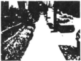
Figure 1 is a sample image taken from an 8mm movie of a sidewalk. One of our test sequences consists of 30 digitized images from this movie. The forward motion between each frame was one and a half feet. On our half speed XL68,000, passes 1 and 2 can process this movie at the rate of one second per frame . The seman tic processing of pass three lakes an additional half second per frame. When applied to this movie, the sys tem correctly discovered and tracked the sidewalk edges, as well as edges of several objects otJ to the right of the sidewalk. No objects were found to be blocking the sidewalk. Figure 2 displays a digitized image from the middle of this sequence with the wire-frame model of pass 3 superimposed. (A similar fit is made for each frame of the movie.) A computer animated reconstruc tion of the outside environment given the world model produced by pass 3 is seen in figure 3. (The detail on the parked car is simulated.) We expect to be running field trials of the entire system in a portable cart trailing behind a blind subject shortly.
XII Incorporation into a Blind Aid
The overall functioning of this system as a blind aid is part of the lineage of a large number of previous lac tile blind aids devices designed over the last twenty years [12][13][14]. The computer vision component and the blind interface component have been separated out from each other via the following reasoning:
- Assuming a perfect computer vision system that knows where every object of interest is located, how could one best communicate this information to a blind pedestrian? What sort of user interfaces and interactions will allow the user to make rapid, accu rate use of the information provided?
- How does one build a portable (wearable!) computer vision system that will locate at least the majority of the objects of interest?
Our solution to 1 has been presented in the previous portions of this paper. Our solution to 2 is to use two output channels - stereo synthetic speech for cognitive (high level) information, and a linear array of 16 tactile elements as a pointing device. The stereo speech unit is a combination of a nonnal speech synthesis system with a audio processing unit that can "throw" the computer's speech, allowing it to appear to come from a particular direction and distance. (For example, a phone pole might seem to announce "phone pole".) The tactile array is a skin tapping device worn as a head-band, each element corresponds to a particular angular direction, and the frequency of taps of an element corresponds inversely to the distance of the feature being pointed to.
Currently we intention to have the speech unit make major announcements (the blind don't want it babbling all the time, they listen to sound shadows and street sounds.) The tactile output will be used for communicat ing more mundane information, such as "you're veering otJ to the left of the sidewalk, veer a bit to the right", by "flashing" the edge of the sidewalk on the appropriate side of the tactile display, should the user veer toward it. In any case, one of the main reasons for puttin·g the whole system on a micro processor, rather than simulat ing it on a mainframe, was to have the capability of expermenting in the real world with various blind inter face systems. Also, despite years of experience in test ing blind aids, it is very hard to tell how the blind will react to a particular device without letting them make extensive use of it under real world conditions.
XIII Perspectives on Future Directions
Within the hardware and timing constraints imposed, we feel that the current system performs well, and cannot be much improved upon. However, for use in a robust blind aid, the system has several limitations which must be overcome. These include the low sensi tivity to low contrast edges in shadowed or complex scenes, and the low resolution (~1 degree/pixel.) More important is the limitation to processing of edge data only, at the exclusion of surface data. It would be nice to have more information about the sidewalk than just where it's edges are, such as how fiat it is, are there any broken sidewalk slabs or holes? Also. the current system must treat any high contrast edge on the sidewalk as a potential object edge, even though most are only flat shadows or stains.
Various surface processing techniques proposed in the literature can solve many of these limit11tions . Tex ture gradients [ 15] should provide a fairly robust broad classification of the scene into flat and upright surfaces . Optical flow can provide approximate dis tance estimates. Luminance gradients could indicate surface curvature, which could be used in identifying {and segmenting) phone poles, walls, automobiles, etc. [10]. Finally, stereo gradients can not only determine general dis tance estimates, but fGr the special case of the almost flat sidewalk, they can be tunned to spot vertical devialions as small as half an inch (such as un-even sidewalk tiles that one might trip upon). More importantly, stereo can determine that a dark patch is flat, and can be safely ignored. This would be similar to the system described in [ 16]. However, for this specialized stereo algorithm to work, it must have a very good estimate as to where the flat sidewalk is in the tlrst place. This is where the other surface processing techniques enter the loop. Such a system could provide very robust perfor mance under even extreme conditions (such as wet (and reflec t ive !) sidewalks in the rain), but at the expense of special purpose hardware.
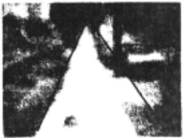
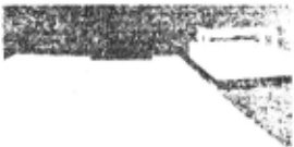
Figure 3. Computer animated reconstruction from model.
Currently we are in the initial stages of designing a surface processing oriented version of our system sys tem along the lines described above, which is to be implemented in VLSI. This system will be characterize by higher resolution (with separate foveal and peripheral resolution), higher frame rates {approaching 30 frames a second), stereo processing, and extensive use of surface processing techniques. It will differ from other vision systems in that it will be optimized for the sidewalk environment. For example, the stereo section will not have to deal with the stereo frame registration problem in its general form, but for the much simplier case of extracting the (mostly flat) ground plane. Evidence indi cates that the vision system of many animals (including man's) has a buill in special case solution for extracting the ground plane, which is similar to our proposed tech nique.
@inproceedings{ijcai1981p134,
  title     = {Real-Time Natural Scene Analysis for a Blind Prosthesis},
  author    = {Peering, Michael F. and Collins, Carter},
  booktitle = {Proceedings of the Seventh International Joint Conference on
               Artificial Intelligence, {IJCAI-81}},
  publisher = {International Joint Conferences on Artificial Intelligence},
  editor    = {Patrick J. Hayes},
  pages     = {704--708},
  year      = {1981},
  month     = {8},
  note      = {Vision: Motion},
  url       = {https://ijcai.org/proceedings/1981/134},
}
TY - CPAPER TI - Real-Time Natural Scene Analysis for a Blind Prosthesis AU - Peering, Michael F. AU - Collins, Carter T2 - Proceedings of the Seventh International Joint Conference on Artificial Intelligence, IJCAI-81 PB - International Joint Conferences on Artificial Intelligence PY - 1981 SP - 704 EP - 708 UR - https://ijcai.org/proceedings/1981/134 ER -Copied
Machine-readable versions of this paper, for tools and AI agents:





