
An Iterative Image Registration Technique with an Application to Stereo Vision
Proceedings of the Seventh International Joint Conference on Artificial Intelligence. Vision: 3-d. Pages 674-678.
© 1981 International Joint Conferences on Artificial Intelligence
Abstract
Image registration finds a variety of applications in computer v1s1on . Unfortunately, traditional image registration techniques tend to be costly. We present a new image registration technique that makes use of the spatiahntensity gradient of the images to find a good match using a type of Newton-Raphson iteration. Our technique is taster because it examines tar fewer potenrial matches between the images than existing techniques. Furthermore, this registration technique can be generalized to handle rotation, scaling and shearing. We. show how our technique can be adapted tor use in a stereo vision system.
- Baker, H. Harlyn. Edge Based Stereo Correlation. Proceedings: Image Understanding Workshop, DARPA, April, 1980, pp. 168•175.
- Barnea, Daniell. and Silverman, Harvey F. "A Class of Algorithms for Fast Digital Image Regis,ration." IEEE Transactions on Computers C-21, 2 (February 1972), 179•186.
- Dudewicz, Edward J .. Introduction to Statistics and Probability. Holt, Rinehart and Winston, New York, 1976.
- Gennery, Donald B. Stereo-Camera Calibration. Proceedings: Image Understanding Workshop, DARPA, November, 1979, pp. 101-107.
- Marr, D. and Poggio, T. "A Computational Theory of Human Stereo Vision." Proceedings of the Royal Society of London 8- 204 (1979), 301 •328.
- Moravec, Hans P. Obstacle Avoidance and Navigation In the Real World by a Seeing Robot Rover. Tech. Rept. CMU-RI•TR•3, Carnegie-Mellon University Robotics Institute, September, 1980.
References were extracted automatically from the PDF and may contain errors.
Full text extracted automatically from the PDF; figures, tables and equations may differ. The PDF is the version of record.
1. Introduction
Image registration finds a variety of applications in computer vision, such as image matching for stereo vision, pattern recognition, and motion analysis. Unfortunately, existing techniques for image reGistration tend to be costly. Moreover, they generally fail to deal with rotation or other distortions of the images.
In this paper we present a new image registration technique that uses spatial intensity gradient information to direct the search for the position that yields the best match. By taking more information about the images into account, this technique is able to find the best match between two images with far fewer comparisons of images than techniques that examine the possible positions of registration in some fixed order. Our technique takes advantage of the fact that in many applications the two images are already in approximate registration. This technique can be generalized to deal with arbitrary linear distortions of the image, including rotation. We then describe a stereo vision system that uses this registration technique, and suggest some further avenues for research toward making effective use of this method in stereo image understanding.
1 his n:~ .· ;;;r.:;ll v1:;:; sponsored by I h.:: Dd·: l1.>0 f,rJvancvd Hw:·::ucll IJrojer. ls Ar,uncy (DOD), AHPA Ordu No. :i!.>fl/, monitored uy the Air rorcc Avionics Labori.ltory Under Contract F33G15-78·C·1551.
The views and conclusions contained in this document are those of the authors and should not be interpreted as representing the official policies, either expre~sed or implied, of the Defense Advanced Research Projects Agency or the US Government.
possible values of h is of size MxM, then this method requires O(M 2 N 2 ) time to compute.
Soeeduo at the risk of oossible failure can be achieved by using a hill -climbing technique. This techn1que oegins with an initial estimate h 0 of the disparity. To obtain the next guess from the current guess hk' one evaluates the difference function at all points in a small (say, 3x3) neighborhood of hk and takes as the next guess h~ + 1 that point that minimizes the difference function .
Another technique, known as the sequential similarity detection algorithm (SSOA) [2], only estimates the error lor each disparity vector h. In SSOA, the error function muzt be a cumulative one such as the L 1 or L 2 norm. One stops accumulating the error for the current h under investigation when it becomes apparent that the current h is not likely to give the best match.
Some registration algorithms use a coarse-fine search strategy. See [6] for an example. One of the techniques discussed above is used to lind the best registration for the images at low resolution, and the low resolution match is then used to constrain the region of possible matches examined at higher resolution.
The algorithm we present specifies the order in which to search the space of possible h's. In particular, our technique starts with an initial estimate of h, and it uses the spatial intensity gradient at each point of the image to modify the current estimate of h to obtain an h that yields a better match. This process is repeated in a kind of Newton-Raphson iteration. If the iteration converges, it will do so in O(M2 log N) steps on the average. This registration technique can be combined with a coarse-fine strategy, since it requires an initial estimate of the approximate disparity h.
4. The registration algorithm
In this section we first derive an intuitive solution to the one dimensional registration problem, and then we derive an alternative solution which we generalize to multiple dimensions. We then show how our technique generalizes to other kinds of registration. We also discuss implementation and PElrlormance of the algorithm.
4. 1 . One dimensional case
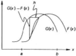
In the one-dimensional registration problem, we wish to lind the horizontal disparity h between two curves F(K) and G(K) = F(K +h). This is illustrated in figure 2.
Our solution to this problem depends on a linear approximation to the behavior of F(x) in the neighborhood of x, as do all subsequent solutions in this paper. In particular, for small h,
so that
The success of our algorithm requires h to be small enouqh that this approximation is adequate. in sect1on 4.3 we will show how to extend the range of h's over which this approximation is adequate by smoothing the images.
The approximation to h given in (2) depends en K. A natural method lor combining the various estimates of h at various values of x would be to simply average them:
We can improve this average by realizing that the linear approximation in (1) is good where F(x) is nearly linear, and conversely is worse where IF"(x)l is large. Thus we could weight the contribution of each term to the average in (3) in inverse proportion to an estimate of IF"(x)l. One such estimate is
Since our estimate is to be used as a weight in an average, we can drop the constant factor of 1 /h in (4), and use as our weighting function
This appeals to our intuition; for example, in figure 2, where the two curves cross, the estimate of h provided by (2) is 0, which is bad; fortunately, the weight given to this estimate in the average is small, since the difference between F'(K) and G'(K) at this point is large. The average with weighting is
where w(x) is given by (5).
Having obtained this estimate, we can then move F(x) by our estimate of h, and repeat this procedure, yielding a type of Newton-Raphson iteration. Ideally, our sequence of estimates of h will converge to the best h . This iteration is expressed by
4.2. An alternative derivation
The derivation given above does not generalize well to two dimensions because the two-dimensional linear approximation occurs in a different form. Moreover, (2) is undefined where F'(x) · 0, i.e. where the curve is level. Both of these problems can be corrected by using the linear approximation of equation (1) in the form
to lind the h that minimizes the L 2 norm measure of the difference between the curve~'
To minimize the error with respect to h, we set
from which
This is essentially the same solution that we derived in (6), but with the weighting function w(x) = F'(x) 2 . As we will see, the form of the linear approximation we have used here generalizes to two or more dimensions. Moreover, we have avoided the problem of dividing by 0, since In (9) we will divide by 0 only if F'(x) = 0 everywhere (in which case h really is undefined), whereas in (3) we will divide by 0 if F'(x) = 0 anywhere.
The iterative form with weighting corresponding to (7) is
where w(x) is given by (5).
4.3. Performance
A natural question to ask is under what conditions and how last the sequence of h~'s converges to the real h . Consider the case
It can be shown that both versions of the registration algorithm given above will converge to the correct h lor lhl < ., , that is, for initial misregistrations as large as one-half wavelength. This suggests that we can improve the range of convergence of the algorithm by suppressing high spatial frequencies in the image, which can be accomplished by smoothing the image. The tradeoff is that smoothing suppresses small details, and thus makes the match less accurate. If the smoothing window is much larger than the size of the object that we are trying to match; the object may be suppressed entirely, and so no match will be possible.
Since lowpass-filtered images can be fillmpled at lower resolution with no loss of information, the above observation suggests that we adopt a coarse-fine strategy. We can use a low resolution smoothed version of the image to obtain an approximate match. Applying the algorithm to higher resolution images will refine the match obtained at lower resolution.
While the effect of smoothing is to extend the range of convergence, the weighting function serves to improve the accuracy of the approximation, and thus to speed up the convergence. Without weighting, i.e. with w(x) "' 1, the calculated disparity h 1 of the first iteration of (10) with F(x) = sin x falls off to zero as the disparity approaches one-hall wavelength. However, with w(x) as in (5), the calculation of disparity is much more accurate, and only falls off to zero at a disparity very near one-half wavelength. Thus with w(x) as in (5) convergence is faster for large disparities.
4.4. Implementation
Implementing (10) requires calculating the weighted sums of the quantities F'G, F'F, and (F') 2 over the region of interest R. We cannot calculate F'(x) exactly, but for the purposes of this algorithm, we can estimate it by
and similarly for G'(x), where we choose ~x appropriately small (e.g. one pixel) . Some more sophisticated technique could be used for estimating the first derivatives, but in general such techniques are equivalent to first smoothing the function, which we have proposed doing for other reasons, and then laking the difference.
4.5. Generalization to multiple dimensions
The one-dimensional registration algorithm given above can be generalized to two or more dimensions. We wish to minimize the L 2 norm measure of error:
where x and h are n-dimensional row vectors. We make a linear approximation analogous to that in (8),
where o/ox is the gradient operator with respect to x, as a column vector:
Using this approximation, to minimize E, we set
from which
which has much the same form as the one-dimensional version in (9).
The discussions above of iteration, weighting, smoothing, and the coarse-line technique with respect to the one-dimensional case apply to the n-dimensional case as well. Calculating our estimate of h in the two-dimensional case requires accumulating the weighted sum of five products ((G- F)F ·· (G - F)F Y' F~; F~. and F,FY) over the region R, as opposed to accumulating one product lor correlation or the L 2 norm. However, this is more than compensated for, especially in high-resolution images, by evaluating these sums at fewer values of h.
4 .6 . Further generalizations
Our technique can be extended to registration between two images related not by a simple translation, but by an arbitrary linear transformation, such as rotation, scaling, and shearing. Such a relationship is expressed by
where A is a matrix expressing the linear spatial transformation between F(x) and G(x). The quantity to be minimized here is
To determine the amount t:.A to adjust A and the amount l:ih to adjust h, we use the linear approximation
When we use this approximation the error expression again becomes quadratic in the quantities to be minimized with respect to. Differentiating with respect to these quanti.ties and setting the results equal to zero yields a set of linear equations to be solved simultaneously.
This generalization is useful in applications such as stereo vision, where the two different views of the object will be different because of the difference in the viewpoints of the cameras. Linear transformations account lor the distortion of planar objects assuming orthographic projection; this is often an adequate approximation to the local distortions of arbitrary objects under the actual perspective projection.
A further generalization is possible to account lor the fact that the brightness values of the pixels may be different in the two views, due to the difference of the viewpoints of the cameras or to differences in the processing of the two images. If we model this difference as a linear transformation, we have (ignoring the registration problem lor the moment)
where a may be thought of as a contrast adjustment and fJ as a brightness adjustment. Combining this with the general linear transformation registration problem, we obtain
as the quantity to minimize with respect to a, fJ, A, and h. The minimization of this quantity, using the linear approximation in equation (11 ), is straightforward. This is the general form promised in section 2. II we ignore A, minimizing this quantity is equivalent to maximizing the correlation coefficient (see, for example, [3]); if we ignore a and fj as well, minimizing this form is equivalent to minimizing the L 2 norm.
5. Application to stereo vision
In this section we show how the generalized registration algorithm described above can be applied to extracting depth information from stereo Images.
5.1. The stereo problem
The problem of extracting depth information from a stereo pair has in principle four components: finding objects in the pictures, matching the objects in the two views, determining the camera parameters, and determining the distances from the camera to the objects. Our approach is to combine object matching with solving lor the camera parameters and the distances of the objects by. using a form of the last registration technique described Sbove.
Techniques lor locating objects include an interest operator [6], zero crossings in bandpass-filtered images [5), and linear features [1]. One might also use regions found by an image segmentation program as objects.
Stereo vision systems that work with features at the pixel level can use one of the registration techniques discussed above. Systems whose objects are higher-lev,el features must use some difference measure and some search technique suited to the particular feature being used. Our registration algorithm provides a stereo vision system with a last method of doing pixel-level matching.
Many stereo v1s1on systems concern themselves only with calculating the distances to the matched objects. One must also be aware that in any real application of stereo vision the relative positions of the cameras will not be known with perfect accuracy. Gennery [4) has shown how to simultaneously solve lor the camera parameters and the distances of objects.
5.2. A mathematical characterization
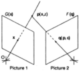
The notation we use is illustrated in figure 3. Let c be the vector of camera parameters that describe the orientation and position of camera 2 with respect to camera 1 's coordinate system. These parameters are azimuth, elevation, pan, till, and roll, as defined in (4). Let x denote the position of an image in the camera 1 film plane of an object. Suppose the object is at a distance z from camera 1. Given the position in picture 1 x and distance z of the object, we could directly calculate the position p(x,z) that it must have occupied in three,space. We express p with respect to camera 1's coordinate system so that p does not depend on the orientation of camera 1. The object would appear on camera 2's film plane at a position q(p,c) that is dependent on the object's position in three·space p and on the camera parameters c. Let G(x) be the intensity value of pixel x in picture 1, and let F(q) the intensity value of pixel q in picture 2. The goal of a stereo vision system is to invert the relationship described above and solve for c and z, given x, F and G.
5.3. Applying the registration algorithm
First consider the case where we know the exact camera parameters c, and we wish to discover the distance z of an object. Suppose we have an estimate of the distance z. We wish to see what happens to the quality of our match between F and G as we vary z by an amount l:.z . The linear approximation that we use here is
where
This equation is due to the chain rule of the gradient operator; CJq/CJp is a matrix of partial derivatives of the components of q with respect to the components of p, and CJF/CJq is the spatial intensity gradient of the image F(q). To update our estimate of z, we want to find the .1z that satisfies
Solving for Az. we obtain
where CJFI(Jz is given by (12).
On the other hand. suppose we know the distances z 1 , i = 1 ,2, .. . ,n, of each of n objects from camera 1, but we don't know the exact camera parameters c . We wish to determine the effect of changing our estimate of the camera parameters oy an amount Ac . Using the linear approximation
we solve the minimization of the error function with respect to .1c by setting
obtaining
As with the other techniques derived in this paper, weighting and iteration improve the solutions for Az and Ac derived above.
5 .4 . An Implementation
We have implemented the technique described above in a system that functions well under human supervision. Our program is capable of solving lor the distnaces to the objects, the five camera paprameters described above, and a brightness and contrast parameter for the entire scene, or any subset of these parameters. As one would expect from the discussion in section 4.3, the algorithm will converge to the correct distances and camera parameters when the initial estimates of the z;'s and care sufficiently accurate that we know the position in the camera 21ilm plane of each object to within a distance on the order of the size of the object.
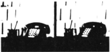
A session with this program is illustrated in figures 4 through 8. The original stereo pair is presented in figure 4. (Readers who can view stereo pairs cross·eyed will want to hold the pictures upside down so that each eye receives the correct view). The camera parameters were determined independently by hand·selecting matching points and solving for the parameters using the program described in (4) .
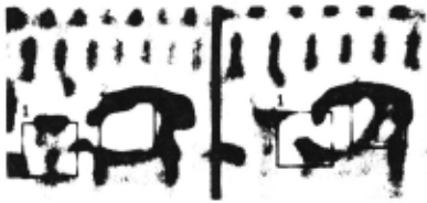
Figures 5 and 6 are bandpass· filtered versions of the pictures in figure 4. Bandpass·filtered images are preferred to lowpass· filtered images in finding matches because very low spatial frequencies tend to be a result of shading differences and carry no (or misleading) depth information. The two regions enclosed in rectangles in the left view of figure 5 have been hand·selected and assigned an initial depth of 7.0 in units of the distance between cameras. II these were the actual depths, the corresponding objects would be found in the right view at the positions indicated figure 5. Alter seven depth·adjustment iterations, the program found the matches shown in figure 6. The distances are 6.05 for object 1 and 5.86 lor object 2.
,-:;·.
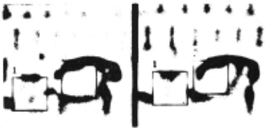
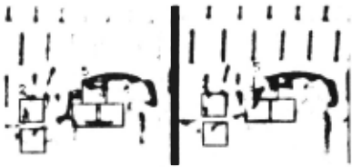
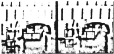
Figure 8.
Figures 7 and 8 are bandpass-filtered with a band one octave higher than figures 5 and 6. Five new points have been hand selected in the left view, reflecting the different features that have become visible in this spatial frequency range. Each has been assigned an Initial depth equal to that found for the corresponding larger region in figure 6. The predicted position corresponding to these depths is shown in the right view of figure 7. After five depth-adjustment iterations, the matches shown in figure 8 were found. The corresponding depths are 5.96 for object 1, 5.98 for object 2, 5.77 for object 3, 5.78 for object 4, and 6.09 for object 5.
"5.5. Future research
The system that we have Implemented at present requires considerable hand·guidance. The following are the issues we intend to investigate toward the goal of automating the process.
- Providing Initial depth estimates for objects: one should be able to use approximate depths obtained from low·resolution images to provide initial depth estimates for nearby objects visible only at higher resolutions.
- Constructin9 a deoth map: one could build a depth map from depth measurements by some interpolation method.
- Selecting points of interest: the various techniques mentioned in section 3 should be explored.
- Tracking sudden depth changes: the sudden depth changes found at the edges of objects require some set of higher·level heuristics to keep the matching algorithm ·on track at object boundaries.
- Compensating lor the different appearances of objects In the two views: the general form of the matching algorithm that allows for arbitrary linear trAnsformations should be useful here.
@inproceedings{ijcai1981p127,
  title     = {An Iterative Image Registration Technique with an Application to Stereo Vision},
  author    = {Lucas, Bruce D. and Kanade, Takeo},
  booktitle = {Proceedings of the Seventh International Joint Conference on
               Artificial Intelligence, {IJCAI-81}},
  publisher = {International Joint Conferences on Artificial Intelligence},
  editor    = {Patrick J. Hayes},
  pages     = {674--678},
  year      = {1981},
  month     = {8},
  note      = {Vision: 3-d},
  url       = {https://ijcai.org/proceedings/1981/127},
}
TY - CPAPER TI - An Iterative Image Registration Technique with an Application to Stereo Vision AU - Lucas, Bruce D. AU - Kanade, Takeo T2 - Proceedings of the Seventh International Joint Conference on Artificial Intelligence, IJCAI-81 PB - International Joint Conferences on Artificial Intelligence PY - 1981 SP - 674 EP - 678 UR - https://ijcai.org/proceedings/1981/127 ER -Copied
Machine-readable versions of this paper, for tools and AI agents:





