
Skill of Intelligent Robot
Proceedings of the Sixth International Joint Conference on Artificial Intelligence. .
© 1979 International Joint Conferences on Artificial Intelligence
Abstract
This paper reviews the development of the intelligent robot and separates skills from high level intelligence. It demonstrates that skills can be represented as virtual mechanisms programmed in software. Virtual mechanisms are defined by controlling both motion and force of a robot arm in a task related cartesian coordinate system. By adding monitoring, a skillful robot system can be built. The skill of an intelligent robot is accumulated in the form of task - particular knowledge that is a specification of the mechanism.
- Feldman, J., et al., "The of Vision and Manipulation to Solve the Puzzle," In Proc. IJCAI-Z!, London, September 1971.
- 2J Ejiri, M., et al., "A Prototype Intelli- gent Robot That Assembles Objects from Plane Drawings," IEEE Trans. Comp., Vol. C-21, pp. 161-170, 1972.
- Shirai, Y., et al., "Visual Feedback of a Robot in Assembly," ETL A.I.R. Group Memo #1, 1972.
- 4J Finkel, R., et al., "AL, A Programming System for Automation," Computer Science Dept. Report CS-456, Stanford University, November 1974.
- Pieper, D. L., "The Kinematics of Manipu- lators under Computer Control," Stanford Ar- tificial Intelligence Project Memo No. 72, Oc- tober 1968.
- Paul, R., "Trajectory Control of a Com- puter Arm," In Proc. IJCAI-Z!, London, Sep- tember, 1971. IJCAI
- Bolles, R., et al., "The Use of Sensory Feedback in a Programmable Assembly System," Stanford Artificial Intelligence Project Memo No. 220, Stanford University, Stanford, CA, October 1973. llOO
- Goto, T., et al., "Precise Insert Opera- tion by Tactile Controlled Robot," In Proc. 4th ISIR, Tokyo, 1974.
- Nevins, J. L., et al., "Computer Con- trolled Assembly," Scientific American, Vol. 238, No. 2, pp. 62-74, February 1978.
- Rosen, C., et Research Applied Eighth Report, SRI CA, August 1978.
- al., "Machine • Intelligence to Industrial Automat ion," International, Menlo Par k, (11J Paul, R., et al., "Compliance and Con- trol," In Proc. ~-~ 1976.
- 12J Takase, K., "Task-oriented Variable Con- trol of Manipulator and its Software Servoing System," In Proc. £!. IFAC Symposium on Information-Control Problems in Manufacturing Technology, Tokyo, 1977.
- Paul, R., et al., "Advanced Industria l Robot Control Systems," First Report, Purdue University, West Lafayette, IN, May 1978.
- 14J Takase, K., et al., "The Design of an Ar - ticulated Manipulator with Torque Control Ability," In Proc. 4th ISIR, Tokyo, 1974.
References were extracted automatically from the PDF and may contain errors.
Full text extracted automatically from the PDF; figures, tables and equations may differ. The PDF is the version of record.
1. INTRODUCTION
Various intelligent robots have been developed by combining computer decision making with mec hanical mechanisms, especially with robot arms . In this field the efforts have been mainl y directed to developing high level in tel ligence system such as for solving puzzles, inte rpreting drawings or recogn1z1ng three dimens ional objects. There has been little study of low level intelligence relating to skill or dexterity of a robot arm. In order to ma ke the motion of a robot arm smoother and more adaptive, a series of studies - ki nemat ics, trajectory calculation, sensory feedback of a robot arm - were undertaken in the Artif icia l Intelligence Project at Stanford Univer sity . But in general we are at the dawn of the s tudy of the skill of robot arms.
The practical study of assembly automation whi ch started as one of the applications of int elligent robots is developing as an in dependent area with remarkable results. Reli abl e assembly systems are being released one aft er another. Although those are compara tive ly special-purpose Low intelligence sys tems , thei~ skills are far more dexterious than those of intelligent robots. It seems the i ncreased skill of the intelligent robot could be obtained only through the integration
of task-particular knowledge that is normally obtained, for example, during the development of special purpose systems. The "Move" com mand in AL, for example, and its modification are not sufficient for specifying the dexteri ous actions of robot arms. "Composing virtual mechanisms by software" seems to be the best control structure for the purpose.
The author has been a visiting scientist of Elec t r ical Engineering at Purdue University, West Lafayette~ IN, since August 1978 until Augus t 1979.
Recently the performance of arithmetic LSI has improved remarkably enabling us to carry out the exact calculation of dynamic models of a robot arm in the servo cycle, and to compose virtual mechanisms in software.
2. INTELLIGENT ROBOTS
In the beginning of 1970's several Hand-Eye systems had been developed at universities and research laboratories in the world. Those robotic systems consisted of a camera and arm with 6 degrees of freedom and computer. At Stanford University a robot which could suc cessfully solve the "instant insanity" puzzle was developed [1]. In this puzzle four cubes with different colored faces must be stacked up so that no two similar color appear on any sides. A robot made at Hitachi could under stand simple drawings and build block struc tures as specified in the drawings [2]. At the Electrotechnical Laboratory a robot was developed, which could insert a beam into a box with small clearance using visual feedback (3J. In these robotic system intelligence had been applied to recognizing a 3-dimensional pattern, understanding a drawing, or solving puzzles.
In order to realize computer control of an arm, several elements had been studied: arm design, servo system, transformation between joint coordinates and cartesian coordinates, computer interface, and robot operating sys tem. Although a good deal of effort was de voted to the computer control of the arm, the arm only could perform "pick and place" opera tions, that is, to pick up an object, to transfer it and then to place it. Some at tempts were made to make the a robot arm more dexterious, for example, by adding tactile sensors in order to grasp objects more dex teriously. None of those attempts was, howev er, successful in developing a reliable ele ments to be incorporated in the robotic sys tem.
It was in the Assembly Automation Systems developed at Stanford University (later re ferred to as the AL System) that an intelli gent robot was first able to act in the prac tical world, emerging from the stage of "play" in the block world [5,6,7]. Assembly processes, such as parts mating and inserting, required adaptive object handling capabilities found only in a human workers were demonstrat ed. These tasks could not be performed by conventional hard automation machines.
In many cases of low volume assembly produc tion programmability was the key factor to enhance the utility of the assembly system. In the AL system much attention paid to the design of task description language. AL of fered the programming structure in which a user could describe an assembly procedure in terms of multilevel commands ranging from the simple "move" command to task-level commands [4]. High-level assembly statements would be expanded into the sequence of move-level com mands in a general manner.
In an assembly system robot arms have to be skillful enough to be able to carry out parts mating and other adaptive motions. In the AL system, precise motions were controlled, based on trajectory calculation and the modification of motions based upon force feedback or touch feedback to adapt to the outer world. To in tegrate these functions into the system, software servoing was used, where a digital computer controlled each motor drive levet directly. By using such a control scheme, the capability of the robot arm was remarkably im proved.
3. PRACTICAL ASSEMBLY AUTOMATION
While general assembly automation was being studied at Stanford University, other practical research was started at several other la boratories and companies. A system, which consisted of position controlled robots and various specially designed tools was developed at Kawasaki Unimate to assemble a gasoline en gine. The work demonstrated a practical ap proach to assembly automation. Hitachi developed a precise insertion robot which operated reliably based on active accommoda tion by a flexible force sensing mechanism [8]. A position controlled robot equipped with a compliance mechanism (RCC) at the wrist which could perform precise insertion quickly without force feedback was developed at Draper Laboratory [9]. At SRI a system which could carry out assembly using a passive accommoda tion table had been developed [10]. In these practical system, global motion was controlled by simple positioning robots and fine accommo dation was accomplished by tools specially designed for the tasks.
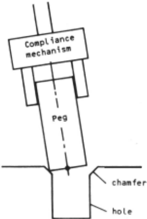
It would be instructive to compare the opera tion of a practical system with that of an in telligent robot. We will take peg insertion as an example. The robot attached with a RCC at the wrist will move a peg into a hole. As shown in Fig. 1, if there is a misalignment between the peg and the hole, the peg will be guided to the hole by the chamfer., The RCC is a compliance mechanism which provides the ac commodation. If a lateral force is exerted at the tip of the peg, it will translate without rotation, and if a torque is exerted at the tip, it will rotate without translation. With the help of the chamfer any translation error is cor rected. During the insertion process i nto the hole any rotation error is corrected.
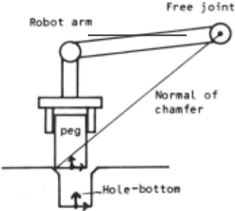
In the AL system the peg insertion could be desc ribed as:
MOVE peg TO hole-bottom
WITH FORCE = 0 ALONG X,Y OF hole-bottom
This command means "move coordinate frame peg to hol e-bottom with two proper joints free so that the x and y components of force are zero ." With this method the peg insertion sometimes becomes impossible. For example, if a fre e joint lies close by the normal of the chamfer as shown in Fig. 2, the angle between chamfer tangent and free surface becomes less then arctangent of friction coefficient. The peg wil l be locked. This is indeed a probable case . This disadvantage .of the AL system shows not only that the system can not perform the peg insertion in this way, but also that the system lacks the systematic representation capability of the necessary skill. It is un des irable that the operation of a robot arm is dependent on its configuration. A user would like to write machine independent programs. In general a robot arm skill consists of pat terns of action to the task environment, in terpretation of results, and the decision of furthe r action. We have to represent the know ledge about an action and its result, whic h is task particular, so that it is robot arm independent.
4. BAS IC CONTROL SCHEME FOR SKILLFUL ROBOT ARM
4.1 Control in Cartesian Coordinate Systems
If the form of assembly is defined, it is most eff icient to use the special devices or tools. Not onl y in assembly, but in general, it is most efficient to design mechanisms suited for the task, and to control the operation of these mechanism using sensory feedback. Hita chi, Draper Laboratory, and SRI had taken this approach in developing assembly systems. Therefore it is senseless to simply compare the capabilities of special-purpose systems and intelligent robots in which generalities are most important. The skill representation capability of the intelligent robot should also be general so as to provide the skill of special-purpose tools. If we could build up virtual mechanisms by software, we would be able to utilize all task particular knowledge which is obtained from the study ~f special purpose tools. And we will be able to ex change tools and skills by software.
What kind of robot arm control would be re quired in order to build up virtual mechanisms by software? It is motion and force control in cartesian coordinate systems. A few methods have been proposed to realize such a type of control [11,12]. We will describe here the direct servoing method in cartesian coordinates that seems to have the highest generality. As shown in Fig. 3 this system provides for the real time transformation between joint coordinates and cartesian coor dinates, the transformation of acceleration and force in cartesian coordinates into joint torques. In addition, coliolis force, centri fugal force and gravity loading force are can celed in real-time.
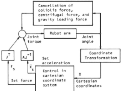
Each joint driving torque T is given by:
where A: inertia matrix of the
robot arm.
J: Jacobian matrix between joint and cartesian coordinate
X : set acceleration in s cartesian coordinates.
F : set force in cartesian s coordinates.
T : coliolis force and n centrifugal torque
T : gravity loading torque g
If the acceleration and force are given, joint driving torque is automatically computed by the system. The equation of motion becomes:
where X: real acceleration in cartesian coordinates.
F: real exerting force in cartesian coordinates.
Assuming that the acceleration caused by the set. force F is small, that X= X and that s s' F = F · s A compliance mechanism can be build up by defining Fs as:
where C: compliance matrix
X: displacement from the origin
A damping mechanism is formed by setting:
where 11 is damping coefficient. Motions are then controlled by setting the acceleration as:
where X r reference input for motion
k: stiffness or gain.
4.2 ~-time Computation
As the dynamic model of a robot arm is very complicated it has been considered impossible to compute joint torques in real-time. Howev er, recent improvement both in calculation al gorithms and in arithmetic elements has now made it realistic. Dynamic model in matrix representation, while simple, was very time consuming to compute. Bejczy developed an ap proximation model which was very fast to com pute. The author formulated the equations of motion in a vector representation. Walker devised a recursive algorithm for evaluating the model in vector representation without redundant repetitive calculation (13]. As shown in Table, we can now calculate joint torques with this algorithm about 200 times faster than using the matrix method.
| P'odel | Language | Computation time |
|---|---|---|
| Matrix Model | Fortran | 7. 9 sec |
| nejczy | Fortran | 0.0025 sec |
| Walker | Fortran | 0. 0335 sec |
| Walker | Floating Point Assembler | 0.0033 sec |
Powerful arithmetic elements such as 16bit x 16bit LSI multiplier with 200 nano second execution time, have also become avail able. It is not difficult to develop special-purpose processors with these arith metic elements for performing fast vector cal culation such as dot product or cross product. It would also be possible to make the calcula tion speed shown in Table ten times as fast. Above considerations show that sophisticated calculation for cartesian coordinates control could easily be carried out in less than 10 milli seconcis.
4.3 Torgue Controlled Robot Arm
Reliable force sensing systems have not been obtained yet, although force sensing, espe cially wrist force sensors have been act ively studied. At the present stage it would be im possible to incorporate the force sensors into the arm control system controlling motion and force in cartesian coordinates. The author and co-workers have developed a robot arm driven by magnetic powder clutches and have demonstrated that the robot arm with open Loop torque control ability could exert a force with an error of +100 grams [14]. The author bel ieves that it is possible to design a com pact arm using torque motors, with a Load capacity of 5 Kg and with a force exertion er ror of +100 grams. Torque control ability of a robot arm is essential if a cartesian coor dina tes control system is to be successfully imp lemented. The use of force sensors will be necessary for the precise control of force.
4.4 Execution Monitoring
If we specify the control of the arm in task relat ed cartesian coordinates, we can make the execution of the task independent of any speci fic robot arm and we can easily analyze the causality between action and its results. In usual execution monitoring, reacting forces are monitored during geometrically specified moti on. The control in cartesian coordinates enab les another form of execution monitoring, for example, force or compliance are specified and the resultant position or velocity are ob served. In the AL system, reaction forces are tes ted in a threshold manner. The AL command for a peg insertion is:
MOVE peg TO hole-bottom
WITH FORCE = 0 ALONG X, Y OF hole-bottom
ON FORCE (Z WRT hole-bottom) > 18·0Z DO STOP
In thi s case, once the z component of the force exceeds 18 oz during motion, the robot arm will stop. However if the characteristics of friction between the peg and hole is as shown in Fig. 3, the peg insertion will stop half way when the velocity exceed Vc. A pro grammer has to have knowledge about the fric tion . A control scheme that specifies force and observes the resultant motion would be more suitable for this task. The peg inser tion task would be more reliable if the inser tion speed versus insertion depth pattern is observed in the performance of the task.
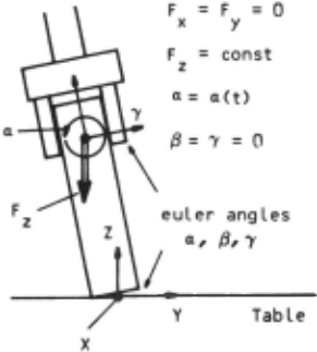
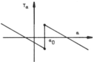
To erect a thin bar on a table is a skill which can not be realized with simple thres hol d tests. If the cartesian coordinates are chosen as shown in Fig. 4 and the bar is ro tated about X axis, an angle versus torque graph will be obtained as shown in Fig. 5. Angl e a 0 , where the bottom plane of the bar comes in full touch with table surface, could be identi fied as the angle where the value of
torque chang~s discontinuously in the graph.
CONCLUSION
The skill of a robot arm consists in the accu mulation of task particular knowledge. This knowledge, that is a specification of the mechanism to perform a task, is embodied by the robot arm in the form of a virtual mechan isms in software. The realization of these virtual mechanisms is by motion and force con trol in cartesian coordinate systems and by monitoring the response patterns. The pro posed method provides a systematic method by which to develop skills for an intelligent robot.
ACKNOWLEDGEMENTS
The author wishes to thank Prof. Richard Paul for helpful comments and for help in preparing the manuscript. He thanks Prof. King Sun Fu for encouragement and support at Purdue University. Document is prepared by Mellanie Boes and drawings by Marc Ream. He also thanks those people.
@inproceedings{ijcai1979p229,
  title     = {Skill of Intelligent Robot},
  author    = {},
  booktitle = {Proceedings of the Sixth International Joint Conference on
               Artificial Intelligence, {IJCAI-79}},
  publisher = {International Joint Conferences on Artificial Intelligence},
  editor    = {Bruce G. Buchanan},
  year      = {1979},
  month     = {8},
  url       = {https://ijcai.org/proceedings/1979/229},
}
TY - CPAPER TI - Skill of Intelligent Robot T2 - Proceedings of the Sixth International Joint Conference on Artificial Intelligence, IJCAI-79 PB - International Joint Conferences on Artificial Intelligence PY - 1979 UR - https://ijcai.org/proceedings/1979/229 ER -Copied
Machine-readable versions of this paper, for tools and AI agents:





