
Automatic Construction of Junction Dictionaries and Their Exploitation for the Analysis of Range Data
Proceedings of the Sixth International Joint Conference on Artificial Intelligence. .
© 1979 International Joint Conferences on Artificial Intelligence
Abstract
A knowledge-guided system is presented for the analysis of range data obtained from the three-dimensional world, A model of the world is defined by a finite set of prototypes of three-dimensional objects, from which the system establishes its own knowledge about the wo rld in the form of a "junction dictionary". Next the system exploits the dictionary for the prediction of missing edges in the analysis of range data originated with real three-dimensional scenes, and thus constructs concise descriptions of the scenes in terms o f vertices, edges, faces and spatial relationships among them, The system is flexible in the sense that the only thing an operator has to do when the world is changed is to replace the model by a new one; the system constructs its own knowledge about the new wo rld and utilizes it for the analysis of range data.
- D. A. Huffman: Impossible objects as nonsense sentences, Machine Intelligence i• B. Meltzer and D. Michie (eds,), Edinburgh Univ. Press, Edinburgh, 295-324, 1971.
- M. B. Clowes: On seeing things, Artif. Intell., 2 (1971), 79-116.
- -- D. Waltz:-Understanding line drawings of scenes with shadows, The Psychology ££ Computer Vision, P. H. Winston (ed,), McGraw-Hill, New York, 19-91, 1975, K. Sugihara: Picture language for skeletal polyhedra, Comput, Gr. Image Process., 8 (1978), 382-405.
- T. Kanade: A theory of Origami world, CMU-CS-78-144, Carnegie-Mellon Univ,, 1978. ~Sugihara: Dictionary-guided scene analysis based on depth information, Progress Report ~1-Q Object Recognition (PIPS-R-No,l3), Electrotech. Labo., Tokyo, 48-122, 1977.
- M. Oshima andY. Shirai: Representation of curved objects using three-dimensional information, 2nd USA-Japan Computer Conference Proceedings, 108-112, 1975.
- F. Kimura and M. Hosaka: Program Package GEOMAP ---Reference Manual (Preliminary Version), Electrotech, Labo,, Tokyo, 1977.
- Y, Shirai: A context sensitive line finder for recognition of polyhedra, Artif. Intell., i (1973), 95-119,
References were extracted automatically from the PDF and may contain errors.
Full text extracted automatically from the PDF; figures, tables and equations may differ. The PDF is the version of record.
1 . INTRODUCTION
It is known that the nature of the t hree-dimensional objects world places great constraints on line drawings of those scenes, and these constraints are exploited for the analysis of scenes. Huffman [1] and Clowes [2] enumerated all of the permissible junctions in line drawings of a certain fundamental class of polyhedra, and used them for categorizing line-segments according to their physical types (i . e ., convex edges, concave edges and cont ours). Wa lts [3], Sugihara [4] and Kanade [5 ] ext ended Huffman-Clowes method to drawings wi th shadows and cracks, to drawings with hidden lines and to Origami world, respectively. Those methods work well for perfect drawings, However, if drawings are imperfect, an unmanageable number of permissible junctions should be considered. Therefore, the knowledge about permissible junc t i ons has been used for the categorization of extracted lines, but not for the extraction of missing lines,
On t he contrary, the author, utilizing the advantage of range information, proposes an appr oach to the use of junction knowledge for the extraction of missing edges in the analysis of range data [6], The basic idea of the app r oach is the following. In the analysis of r ange data we can distinguish convex, concave, obscuring and obscured lines from each other without using any additional information; the junct i on knowledge is not necessary for the line categorization. Therefore, this knowledge can be used for another purpose, that is, for the prediction of missing edges, Comparing a line drawing extracted from the range data with the list of the permissible junctions, we can tell whether the present drawing is consistent with the physical world or not, and we can, in the latter case, predict the locations and physical categories of missing edges, Thus the extraction of edges can be efficiently guided by those predictions. This approach is practical, since "noisy" raw range data can be dealt with, One of the greatest shortcomings of the above approach (as well as other approaches to the exploitation of the junction knowledge) is the trihedral-vertex condition, that is , it is assumed that every vertex of a body in the scene has exactly three faces, If we would simply remove this assumption, there would occur an infinite number of permissible junctions, which could not be stored in a finite size of the computer memory, The present study aims at circumventing the above shortcoming, that is, we represent the knowledge about nontrihedral junctions as well as trihedral ones, The approach we shall take is automatic compilation of the junction knowledge. A model of the world is defined by a finite set of prototypes of polyhedra, and the junction knowledge associated with this world is constructed automatically and is incorporated in the system for range-data analysis, Since the world is restricted to a finite number of polyhedra, the number of permissible junctions is also finite and the knowledge about the world does not swell out,
2, OUTLINE OF THE SYSTEM ---
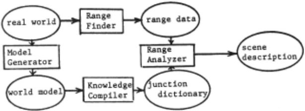
The outline of the functions of our system is shown in Fig.l, where rectangles denote system components, circles denote information and arrows denote flow of information, It is assumed that the real world is composed of polyhedra which are taken from a finite set of prototypes, The system consists of the four subsystems:
- Range Finder --- a subsystem which obtain range data from real scenes by triangulation,
- Model Generator --- an interactive subsystem by which an operator can generate a model of a real world as a finite set of polyhedra,
- Knowledge Compiler --- a subsystem whose input is a world model and whose output is a junction dictionary,
- Range Analyzer --- a subsystem which analyzes range data and establishes concise descriptions (in terms of vertices, edges, faces and spatial relationships among them) of the scenes; in each step of the analysis the subsystem consults a junction dictionary in order to predict missing edges,
We shall go into details of those subsystem in the following sections.
3. RANGE OBSERVATION
Fig,2 shows a triangulation method for obtaining range information about a scene. A light beam is projected from a source 0 to the scene and the illuminated spot is observed from another angle by a TV camera 0 1 , The direction of the beam is specified by the point (i,j) at which the beam intersects a fixed plane S. Let d(i,j) denote the distance of the image P'(i,j) of the illuminated spot P(i,j) from the left margin of the TV image plane, as is illustrated in Fig.2. A three-dimensional location of the point P(i,j) can be easily calculated by simple geometry, if we know d(i,j) and the spatial relation among the light source 0, the TV camera 0 1 and the plane S, We shall call the array of the data d(i,j)'s (i=l, ··· , m, j·l, ··· , n) a range picture (though d(i,j) is not a range itself). For practical purpose, a vertical slit light can be used instead of a spot light (see Oshima and Shirai [7)),
Note that we can not always observe the range of a given point (i,j), because the range is obtained only when the illuminated spot P(i,j) can be seen from the TV camera, The line-segment AB in Fig.2, for example, is hidden from the TV camera by another object in front of it, and thus the range data associated with this line-segment are unknown. Therefore, in the range picture (i.e,, the two-dimensional array of d(i,j)'s) there are usually a few regions whose values are undefined,
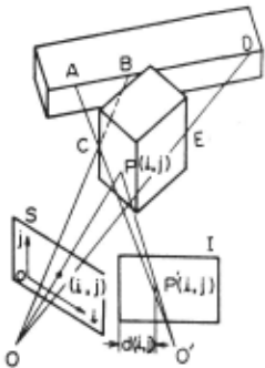
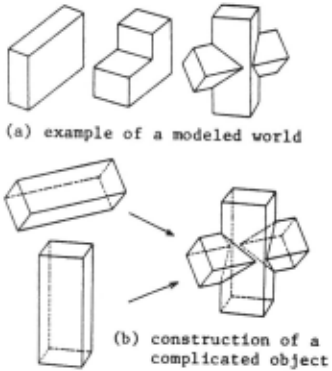
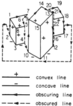
Fig.4. Line drawing representing the scene in Fig.2.
4. MODELING OF A WORLD
The basic part of Model Generator is written in a high-level language named GEOMAP, which is a FORTRAN subroutine package for handling descriptions of three-dimensional solids developed by F. Kimura of Electrotechnical Laboratory [8]. This subsystem is used interactively for the construction of a world model as a set of prototypes of polyhedra. In order to construct a model of each polyhedron, an operator first (1) generates primitive polyhedra such as a rectangular brick, a wedge and a prism/cone with a po.lygonal base, and next (2) modifies and combines them into a required shape by set-theoretical operations such as a union, an intersection and a subtraction and/or affine transformations. An operator can also obtain two-dimensional projections of the modeled objects seen from an arbitrarily specified viewpoint.
Fig.3 (a) shows an example of a modeled world. The pr ocess for the construction of the rightest object is shown in Fig.3(b), where two rectangular bricks are generated first and then they are merged into one by a set theoretical union operation.
5. CONSTRUCTION OF JUNCTION DICTIONARIES
5.1. Line Categories
Fig.4 shows a line drawing of the scene in Fig.2, where two blocks are put on a desk surface. The lines in the drawing are classified according to their physical properties into the four categories: convex lines, concave lines, obscuring lines and obscured lines. While the first three categories occur in usual line drawings, the last category is peculiar to range pictures obtained by triangulation. For example, the right side of A in Fig.2 is obscured by C when seen from the camera O', and consequently A is on an obscured line and C is on an obscuring line, as is illustrated in Fig.4,
5.2. Enumeration of Possible Junctions
We will assume that (1) the scene is composed of polyhedra taken from a finite set of prototypes, and that (2) accidental alignments do not occur in the scene. We will call a junction possible if it can appear in a line drawing of the scene under those assumptions, and call it impossible if otherwise.
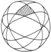
Suppose that a vertex of a polyhedron (made of solid material) is put on the center of a unit sphere. Each face around the vertex, when extended, intersect the unit sphere at a great circle, as is shown in Fig.5. These great circles divide the surf ace of the sphere into a finite number of spherical polygons. Then, some of the spherical polygons are in solid material and the others are in an empty space; we will call the former polygons occupied polygons and the latter ones ~polygons. A vertex of a cube, for example, generates eight spherical polygons, one of which is an occupied polygon and the other seven are empty polygons.
The light source and the camera are supposed to be put on (the same or distinct) empty polygons. Then, the subsystem classifies the area of surfaces around the vertex into the two groups: the area which is visible from both the light source and the camera (i.e., the area whose range can be observed) and the area which is invisible from either of them. And finally, the subsystem constructs a perspective view of the vertex (seen from the camera) in terms of the four categories of lines, .and thus obtains a possible junction.
Special types of junctions occur when the camera or the light source is on one of the (extended) face plane. For the enumeration of such kinds of junctions, we have to consider putting the camera and/or the light source on an edge or a corner of a spherical polygon. Once the positions of the camera and the light source are fixed, the processing for the construction of a junction is the same as the above case.
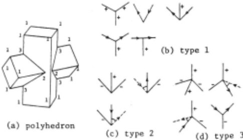
The polyhedron shown in Fig.6(a) has 24 vertices (including hidden vertices which are not shown in the figure), and they are classified into three types 1, 2 and 3 as are shown in the figure: the vertex of type 1 consists of three faces which meet at three convex edges, the vertex of type 2 consists of three faces which meet at one convex edge and two concave edges, and the vertex of type 3 consists of four faces which meet at two convex edges and two concave edges. All the possible junctions associated with the vertices are listed in Figs.6(b), (c) and (d), where an arc connecting two arrowed lines denotes an obscuring/obscured relationship.
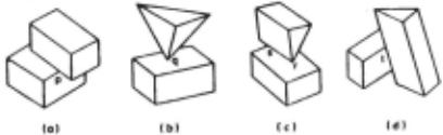
The above enumeration is sufficient for isolated bodies, but in real scenes several bodies contact each other. Because of the assumption (2) permissible ways of contacts of two bodies are (a) face to face, (b) point to face, (c) edge to face and (d) edge point to edge point as is shown in Fig.7. The subsystem generates the possible junctions associated with the vertices such as q and r as well as the pseudo-vertices such as p, s and t.
5.3 Junction Dictionary
A junction dictionary is constructed in a form of a directed graph whose nodes are all sub-configurations of possible junctions and whose arcs represent the relationships that the initial node can be changed into the terminal node by an addition of one line.
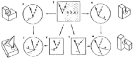
Part of the junction dictionary is shown in Fig.8, where seven junctions and relationships between them are illustrated. The three junctions in rectangles (t, v and y) are impossible ones and the four in circles (u, w, x and z) are possible ones. The drawings beside the possible junctions show the examples of the situations in which the junctions occur. An arrowed arc connecting two junctions denotes an addition of a line. If, for example, we add a convex line in the shaded area of the junction t in Fig.8, we get another junction u. Adding, furthermore, a concave line to u, we obtain w and thus we get the path (t, u, w) from t to w. When we exchange the order of addition of the two lines, we get another path (t, v, w). Those paths suggest the existance of new lines and guide the analysis of the range data. If a junction of the type u is found in range-data analysis, the dictionary tells us that a concave line "may" exist at that junction. If, on the other hand, a junct ion of the type v is found, the dictionary says that a convex line "must" exist because v is impossible and w is the only possible junction that has v as a sub-configuration.
6. RANGE DATA ANALYSIS ------
6.1 . Experts for the Analysis
The subsystem for the range data analysis is cal led DARP (Dictionary-guided Analyzer for Range Picture). The input to DARP is a range picture originated with a real scene and the output is a collection of labeled line drawings of all the objects in the scene.
DARP is composed of many experts: a line predictor, when a junction is given,~sults a dictionary and predicts missing lines around the given junction; a prediction tester judges whether predicted lines really exist or not; a line tracker, when a new line is found at a junct ion, tracks it as far as possible and extracts the whole part of the line; a straight-line adjuster finds straight lines which approximate to the strings of points extracted by the line tracker; a body partitioner, using the knowledge of what types of junctions occur when two bodies contact each other, decomposes the line drawing into smaller ones; a vertex-position corrector revises a posi tion of a junction whenever a new line is connected to the junction.
The processing of DARP is divided into the two parts: a pre-processing and the main processing. The pre-processing consists of several routines which are executed one by one sequentially. In the main processing, on the other hand, the experts interact each other and the system chooses its next step in such a way that the information at hand is used most efficiently [6]. The control structure is based on the idea of a heterarchical program by Shirai [9]).
6.2. Example
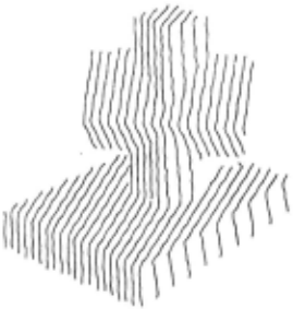
Fig.9 shows a range picture (represented by light-stripe images) of the scene composed of two objects --- a supporting block and a complicated body consisting of two bricks; both of them are in the world model in Fig.J(a). Fig.lO shows how the system analyzes the scene.
DARP, in its preprocessing, extracts contour lines and locates junctions on them. In the main processing DARP first focuses its attention to junction Jl in Fig.lO(a), where junction Ji is represented by i. Jl is a junction of type t in Fig.8. (Note that the internal lines JlJ3 and J3J2 have not yet been found.) The line predictor generates predictions about new lines around Jl, and the prediction tester finds a concave line. The line tracker follows it and extracts the whole line (as a string of points), and the straight-line adjuster finds a new junction, say J3, on the new line and replaces the string by two straight line-segments JlJ3 and J3J2. Thus the type of Jl is changed to x in Fig.8. Since no other lines are found around Jl, DARP terminates the analysis of Jl.
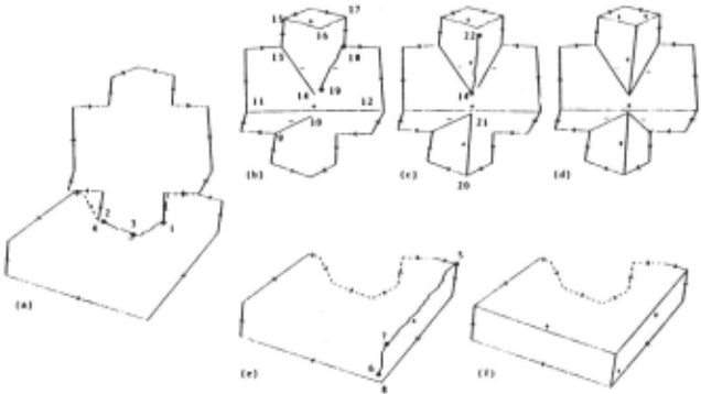
Next DARP picks up junction J4 and the line predictor suggests a concave line in the right side of the junction, The prediction tester finds that the predicted concave line has already been extracted, and consequently the two junctions J2 and J4 are merged into one, which is renamed J2. Then, the drawing is decomposed along the concave lines JlJ3 and J3J2, because Jl and J2 are the junctions that occur at the contact of two bodies (Fig,lO(b) and Fig.lO(e)),
When J5 is examined, a new convex line J5J6 and a new junction J7 are found (Fig.lO(e)), and when JB is examined, JB and J6 are merged into one. By similar processing DARP establishes a concise description of the supporting block as is shown in Fig,lO(f). The other body is analyzed similarly and DARP obtains the final line drawing shown in Fig.lO(d). The numbers assigned to junctions show the order in which the lines and the junctions are extracted,
Though seven edges come close to each other around the central portion of the scene, DARP can construct a perfect line drawing, because the data processing is supported by appropriate predictions of missing lines based on the junction dictionary.
7, CONCLUDING REMARKS
We have studied the dictionary-guided system for the analysis of range data obtained from three-dimensional scenes. Once a world model is given as a set of polyhedra, the system enumerates all of the possible views of vertices and compiles a junction dictionary associated with the given world, and uses it for the analysis of real scenes, Since the junction dictionary suggests missing lines at each step of the analysis, the edge detection is executed efficiently and reliably. Moreover, since the dictionary suggests how to organize the extracted lines, the output is not merely a collection of lines but a structured description of vertices, edges and faces, which is useful for later processings such as the identification and/or the manipulation of objects. The system is flexible in the sense that the only thing an operator has to do when the world is changed is to replace the model of the world with a new one, from which the system generates its own knowledge about the new world and uses it for the scene analysis, The present system has week points, First, the junction dictionary conveys only local knowledge, Therefore, the system is sometimes insensitive to global inconsistency of the drawing, and it decomposes the scene into pieces smaller than the modeled prototypes, Secondly, obscured lines can not be identified if they are caused by the edges which are out of the picture; this difficulty seems to be essential to triangulation.
ACKNOWLEDGMENTS
The author would like to express his appreciation to Dr. Noboru Sugie and Dr. Yoshiaki Shirai for valuable discussion; to Dr. Fumihiko Kimura for offering the splended software GEOMAP; to Dr. Masaki Oshima for offering a range findin·g device. This work has been done as part of Pattern Information Processing System Project (PIPS-Project) of Ministry of International Trade and Industry of Japan.
@inproceedings{ijcai1979p188,
  title     = {Automatic Construction of Junction Dictionaries and Their Exploitation for the Analysis of Range Data},
  author    = {Sugihara, Kokichi},
  booktitle = {Proceedings of the Sixth International Joint Conference on
               Artificial Intelligence, {IJCAI-79}},
  publisher = {International Joint Conferences on Artificial Intelligence},
  editor    = {Bruce G. Buchanan},
  year      = {1979},
  month     = {8},
  url       = {https://ijcai.org/proceedings/1979/188},
}
TY - CPAPER TI - Automatic Construction of Junction Dictionaries and Their Exploitation for the Analysis of Range Data AU - Sugihara, Kokichi T2 - Proceedings of the Sixth International Joint Conference on Artificial Intelligence, IJCAI-79 PB - International Joint Conferences on Artificial Intelligence PY - 1979 UR - https://ijcai.org/proceedings/1979/188 ER -Copied
Machine-readable versions of this paper, for tools and AI agents:





