
The Experimental LISP Machine
Proceedings of the Sixth International Joint Conference on Artificial Intelligence. .
© 1979 International Joint Conferences on Artificial Intelligence
Abstract
!'his ma c h i ne i s sp ec ially de s igne d pow e rful en ough t o implement an efficient LIS P interpr e ter in mi croc o de s . A LI SP processor mo dule and a main memo ry module are connected to the unibus of a LSI-1 1 s ystem. The LISP pr o ce s sor module is the microcoded device with a writable co ntrol stor a ge that interpr e ts a LI SP pr o gram in the main mem o ry. Four microprocessor slices(Am 2903) and one microprogram sequencer(Am 2910) are used.
- Taki, K. , Kaneda, Y. and Maekawa, S. "The Experimental LISP Machine." Tee. Report of the Professional Group on Computer Architecture of IPSJ, 32-3, Sept., 1978 (in Japanese).
- Bawden, A. et al "LISP Machine Progress Report." MIT AI Lab. Memo. , No. 444, Aug. , 1977.
References were extracted automatically from the PDF and may contain errors.
Full text extracted automatically from the PDF; figures, tables and equations may differ. The PDF is the version of record.
1 . INTRODUCTION
The LI SP i s widely used in the artificial intelligence research community. However LISP processing systems have several nontrivial problems to be solved. One of the most important problems i s t hat the computing time of getting solutions of the problems is much slowe r than the case o f numeri cal problems. The main reason for t he slow speed of computation is due to an unf itness o f LISP and a conventional computer a r chitecture a t pre sent.
An approach t o thi s problem is t o des ign a machi ne whose architecture is LISP oriented and code structure more closely reflects that of the language . 'l'he machine proposed here i s an exper imental mi croprogramable comput er system for LISP . 'l'hi s machjne is specially designed powerful enough to implement an efficient LISP interpret er i n microcodes.
2 . 'riU: LISP MACHINE SYSTEM
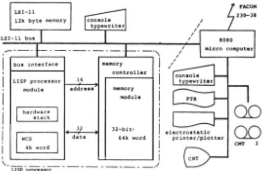
Our LISP machine i s a s tand alone personel computer, and Fig .l i l lustrates the structure of t he machi ne .
'l'he LISP processor module and the shared main memory module A.re connected t o t he lJN[BU;, o f the LST-ll ;,ystem(DEC Co ) . The 1.:;1- 11 acts rw t he ma~; ter processor of the ~;y~jtem and play~· t he r·oLes o f system i nitjal Lzution , ir1puL and uutput, and control s of the LTSI' pr occ::sor modul e . The LISP processor module is a mLcropro[~r~ed devi ce with a writable control storage (WCS ) that interpret s a LJ;,p program ::;tar ed i n the main memory. 'l'lt<: mai n memu r·y modul" Ls a 64k wor ds(32- bit "''' r·ds) ::emi conductor mf:'mory and i t s access time is about 75 nsec. The main memory module is also accessible from the LSI-11 using a page mode access mechanism. A data transfer unit between the LISP proces sor module and the main memory module is a 32-bit word.
3 . THE LISP PROCESSOR MODULE
The LISP proces sor module i s implemented with a mi cr oprogrammed architecture(Fig.2). It s kerne l consist s of an arithmetic and l ogic uni t( ALU) and a computer control unit(CCU). The CCU has a WCS(4k of 56-bit words) to accommodate the specialized microcodes to support the LISP.
It has hardware for extracting specialized fiel ds in a word, called field extractor, and the mapping memory which converts a main memory address into 3-bit code.
LISP prooea&oc It has not a cashe , but has a hip;h speed stack( hk of 16- bit words) acts as a high speed main memory area for a stack , which is where most of the memory references go in LISP . It has also three buses called A bus, Y bus and B bus . A bus is the data bus , Y bus is the destination bus and B bus is the data bus between the CCU and ALU through which a constant value i s supplied to the ALU .
Fig .l Hardware s tructure of the machine
3.1 The ALU and CCU
The ALU is an array of four 4- bit expandable bipolar microprocessor s lices(Am 2903) . And the CCU is a control unit of the machine and consi.sts of a microprogram sequencer(Am 2910) , WCfJ and other circuits . The Am 2910 is an addre:>:~ sf>quencer intcnrle<l for controlling the }Wq1l<'TI<'C' of execution n r microinstructions :oto n·d in UH' WCS ( act·r~:' ~' tim<' i :o r:tbout 1 )0 nseC') . Besides the capability o f sequent ial access, the sequencer provides conditional branchings to any microinstructions within its 4096 microwords range . 'Phe flag regi ster contains ALU ' s flags, the mapping memory flap;s and other flags. All these flags are available for conditional branching under the microprogram control.
3.2 The Hardware Stack , Field Extractor , Mapping Memory and Bit Addressing Unit
The hardware stack is a l~096 16-bi.t word memory (access time of the memory chip ·is about 70 nsec ) . Two pointer r egisters S'rl' and SAR are provided for stack operations.
The field extractor locates on the A bus and all data to the ALU flow through the unit. This unit is useful to extract a fixed specified fi eld of data .
The mapp ing memory is a lk 3- bit word memory. Whenever the main memory references are made the addr ess is gated to the unit . lk 3-bit word memory is considered a s a tag table whose entries are associated with every 6h words sections of the main memory. The supplied address is converted into three bits code which indicates the data type of the object. By usinp; this three bits code rapid conditional .Jump is possible in the microcodes.
The bit addres};ing unit is a functional unit which tests and sets a bit on a predefined bit table in the main memory . 'l'his unit Ls prepared for realizing the rapid garbage collection .
3 .3 Microprogram Instructions
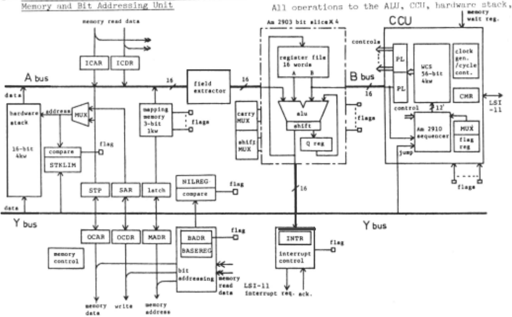
mapping memory and other circuits Rre entirely under the control o f microcode words of the WCS. The microinstruction is a 56-bit word divided into fields . Two types of microinstructions are provided . The type l instructions can provide a constant value to the ALU through the B bus , type 2 instructions are conditional branching instructions which can transfer controls to any microcode locations depend on condition flap;s .
4. DATA AND FUNCTION TYPES
There are four data types, small integer, i nteger , symbolic atom and list. Small integer, +8191 to - 8192 , doesn 't occupy any memory words. I ntegers are represented in two's complement notation. Symbolic atom are stored as four consecutive words, each of which is divided i nto t wo 16-bit cells termed the function body cell , attribute cell, argument cell, top-value cel l , property list cell , print name cell and two unused cells .
'fhree types microcoded subroutine functions, MSUBR , MRSUBR and MHFS\JBR are provided. MRSUBR and MRFSUBR are recursive functions and MSUBR is not .
MR:;urm: Jo;VAL , APPLY , MAP, GET , F.QUL , etc . MHf~SUBR: CONll , f'R()G, AND, DE , SETQ, etc . MSUTlR: CAR, CUR, CONS, EQ, NULL, ATOM, etc.
5 . IN'fEl1PRETER
In our system the user program is reconstructed into a binary tree structure and interpretation o f' the program i s made hy traversing the tree in the endorder fashion .
'l'he functiona.l culling :is the basic main control s t rue t ure in LU;[' . As mentioned above , the LISP machine f'uuct io:1 callinf, is made fast through U1e use or the hardware stack and microcodes. 'J'he stack i. s formatted .into frames; each frame containes a header, arguments, local variable value slots, and a push down list for i ntermedia1. e results. The header gives the function which owns the frame, a pointer to the function body, links this frame to previous frames, and remembers the program counter and mic r oprogram counter . TARAI-3 TARAI-4 TARAI-5 TARAI-6
inches) . The LISP interpreter of the machine is entirely microcoded and stored in the WCS . The program size of the first version is about 1200 microinstruction steps.
In order to evaluate our LISP machine, we executed the benchmark programs of the second LISP contest of IPSJ(Information Processing Society of Japan). Our interpreters execution times of these programs were shorter than those of any participants of the contest(almost all typical LISP systems in Japan such as HLISP installed HITAC-8800 and OLISP installed NEC system 800-2 were attended).
Examples of typical two benchmarks(e.g. TARAI and TPU) are shown in Table l. TPU is a theorem prover based on the unit binary resolution priciple written by C.L. Chang and TARAI is a very short program which does almost recursions only except the very simple functions GREATERP and SUBl .
These measurements showed that the architecture of our machine nicely fits in the control structure of the LISP language and realizes a very rapid execution of LISP programs.
ACKNOWLEDGMENTS
The authors wish to express their thanks to Messrs. Toshio Shimada and Yoshinori Yamaguchi of Electrotecnical Laboratory for their useful suggestions and discussions.
@inproceedings{ijcai1979p189,
  title     = {The Experimental LISP Machine},
  author    = {Taki, Kazuo and Kaneda, Yukio and Maekawa, Sadao},
  booktitle = {Proceedings of the Sixth International Joint Conference on
               Artificial Intelligence, {IJCAI-79}},
  publisher = {International Joint Conferences on Artificial Intelligence},
  editor    = {Bruce G. Buchanan},
  year      = {1979},
  month     = {8},
  url       = {https://ijcai.org/proceedings/1979/189},
}
TY - CPAPER TI - The Experimental LISP Machine AU - Taki, Kazuo AU - Kaneda, Yukio AU - Maekawa, Sadao T2 - Proceedings of the Sixth International Joint Conference on Artificial Intelligence, IJCAI-79 PB - International Joint Conferences on Artificial Intelligence PY - 1979 UR - https://ijcai.org/proceedings/1979/189 ER -Copied
Machine-readable versions of this paper, for tools and AI agents:





