
A Scanning Laser Rangefinder for a Robotic Vechicle
Proceedings of the Fifth International Joint Conference on Artificial Intelligence. Robotics. Pages 762-767.
© 1977 International Joint Conferences on Artificial Intelligence
Abstract
A scanning Laser Rangefinder (LRF) which operates in conjunction with a minicomputer as part of a robotic vehicle is described . The description includes both hardware and software. Also included is a discussion of our functional requirements relative to the state - of-the -art; a detailing of the instrument and its performance; a summary of the robot system in which the LRF functions; the software organization, interfaces, and description; and some applications to which the LRF has been put.
- Canberra Electronics, Meriden, Conn. "Constant Fraction Discriminator, Model 1427.
- Johnston, A.R., "An Experiment in Manipulator Control with Proximity Sensors," TM 33-678, Jet Propulsion Laboratory, California Institute of Technology, April 1, 1974.
- Miyake, K., Appl Opt. 15, 1684 (1976).
- Nanofast Corp., Chicago•, Illinois. Half-max discriminator, for example.
- Nitzan, D., Brain, A. E., and Duda, R.O., "The Measurement and Use of Registered Reflectance and Range Data in Scene Analysis," Proceedings of the IEEE, 65(2), February 1977.
- Reisse, R., Cheley, R., and Poultney, S.K., "Single Photon Detection and Subnanosecond Timing Resolution with the RCA 31034 Photo- multiplier," Rev. Sci, Instr. 44, 1666 (1973).
- Whitney, W.M., "Human vs Autonorous Control of Planetary Roving Vehicles," IEEE Symposium on Systems, Man & Cybernetics, Dallas, Oct. 1974. qohntlcs-3: LPwls
References were extracted automatically from the PDF and may contain errors.
Full text extracted automatically from the PDF; figures, tables and equations may differ. The PDF is the version of record.
A SCANNING LASER RANGEFINDER FOR A ROBOTIC VEHICLE
R. A. Lewis and A. R. Johnston
Jet Propulsion Laboratory, California Institute of Technology, Pasadena, California 91103
ABSTRACT
A scanning Laser Rangefinder (LRF) which operates in conjunction with a minicomputer as part of a robotic vehicle is described . The description includes both hardware and software. Also included is a discussion of our functional requirements relative to the state- of-the-art; a detailing of the instrument and its performance; a summary of the robot system in which the LRF func tions; the software organization, interfaces, and description; and some applications to which the LRF has been put.
INTRODUCTION
Development of the instrument described in this paper was begun in 1972 as a part of the con tinuing Robot Research Program at the Jet Propul sion Laboratory (Ref. 8). The Program was concern ed with techniques for moving a vehicle about at a remote location and accomplishing useful tasks autonomously, without detailed human interaction. The tasks of interest included location and manipu lation of rock samples on the surface of a planet.
The motivation for development of the Laser Rangefinder (LRF) was to provide a means for geometrical, three-dimensional location of objects or surfaces in the neighborhood of the robot vehicle for use as input information to the auton omous control system. The LRF instrument was a part of a " vision" system that also included two television cameras and a minicomputer.
The potential usefulness of laser ranging devices to the fields of Artificial Intelligence and Applied Robotics is only beginning to be realized. Early programs tended to rely primarily on passive optical devices such as single or stereo television cameras. Hare recently, investigators such as Nitzan, et al. (Ref . 5) have begun to explore the applications of lasers in providing reflectance as well as range data. A system such as the LRF described herein is a useful adj unct to a robot system in that 1) it provides an inde pendent determination of object location, 2) its error characteristics and sensitivities are cliff e r ent from those of a television sys tern (i.e., a LRF works in the dark), 3) in many instances the desired information can be obtained faster, and 4) the LRF beam may be directed such that it appears in a television image and thus aid in such tasks as the matching of picture elements in stereo pairs.
The most important probl em initially addressed was that of locating a rock-like object for grasp ing by a manipulator. A second problem, which is just beginning to receive attention, is that of obstacle detection or terrain mapping for use during vehicle motion. These applications shaped the performance requirements for the LRF instrument.
The instrument beam was to be directed at specified points or scanned over a specified area under computer control. The manipulator hand was roughly the size of a human hand, so a capability to determine the position of a target within a few centimeters was desired. This accuracy was needed over a region extending roughly from 1 meter to 3 meters range. In addition , ranging with good repeatability to 30 to SO meters, but without tl1e centimeter accuracy requirement, was needed for · vehicle motion inputs. A capability for outdoor operation in full sunlight was also required. Reasonably fast operation such that the overall function of the robot would not be slowed while waiting for data was also important, but no hard requirement for exceeding a critical minimum data rate was envisioned . Finally , since the ultimate application was to a planetary rover, a technique which could uitimately result in a reasonably small and rugged package was needed.
*This paper presents the results of one phase of research carried out at the Jet Propulsion Laboratory, California Institute of Technology, under Contract NAS 7-100, sponsored by the National Aeronautics and Space Administration.
Nany rangefinding instruments have been devel oped, both with better accuracy· and with longer maximum range capability than we needed. However, no existing instrument would do the entire job.
For our application, a solid-state injection laser rather than other types of lasers or an LED source was desirable in order to ensure both a small package and a future capability of operating at dis tances exceeding 30 meters. With such a laser, pulsed operation was necessary. Averaging of the transmit-time measurement over many light pulses was incorporated in order to reduce the inevitable noise in the data to a reasonable level. Averaging of the pulse travel time is an analogous to the heavy output filtering typical on CW phase type LRF instruments.
In summary, these were the technical con straints and requirements for the instrument described in the following sections.
INSTRUHENT llESCRIPTION AND PERFORHANCE
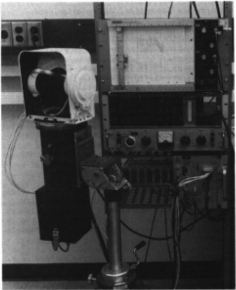
Physically, the LRF (Fig. 1) consists of two packages: (1) an optical head containing the light source, photo-detector, and optics for forming and pointing the beam, and (2) an electronics package containing the control and measurement circuits.
An overall block diagram of the LRF is pre sented in Fig. 2. The light source is a gallium aluminum arsenide solid-state laser. A clock, not shown in Fig. 2, drives the laser pulser at a 10 kHz rate and also provides timing for related functions. The detector is a type C31034 photo multiplier having a gallium arsenide photo sur face with spectral sensitivity to match the laser emission (Ref. 7). A gallium aluminum arsenide laser operating near 0.84 mm was selected, rather than a GaAs-type emitting at 0.90 mm, because the photomultiplier cathode efficiency drops off very rapidly at wavelengths approaching 0.9 mm.
The constant-amplitude current pulse used to drive the laser is sampled at the pulser by an inductive loop and is used as the timing reference for meas urement of the light pul se transit time. The photomultiplier output pulse is of variable amplitude, depending on the nature of the target surface and its range. As a r esult, a module called a constant fraction discriminator (Ref. 1) is introduced to minimize the effect of the amp litude of the reflected lignt pulse on the range rneasurernen t.
The time interval measurement itself is made by a time-to-pulse-height converter (Ref. 6), a module which produces a relatively long (2 micro second) output pulse for each start-stop pulse pair accepted. The amplitude of this output pulse is accurately proportional to the start-stop time interval, and is subsequently sampled, averaged over many pulses, and converted to a digital form for transmission to the computer which interfaces in real time with the LRF instrument. Both critical elements in the time interval measure ment, the constant-fraction discriminator and the time-to-pulse-height converter, are commercial nuclear physics instrumentation.
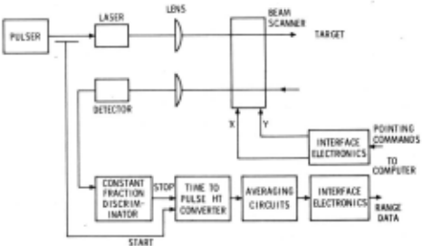
The computer, a General Automation SPC 16-85, also supplies pointing commands whicl1 are used to drive the beam scanner. The scanner is a gimballed mirror driven by stepper motors in elevation and azimuth. The single mirror reflects both trans mitted and received light beams, but there are separate, nonoverlapping transmitter and receiver apertures.
Although the time-to-pulse-height conversion is sufficiently linear for our purposes without modification, slow delay time drifts in the elec tronics would seriously limit the accuracy of the LRF. In order to eliminate the effects of these drifts and permit object location to roughly one centimeter, a self-calibration procedure has been incorporated. This procedure is equivalent to operating the instrument in a comparison mode in which an unknown position is determined relative to a known target. However, errors due to reflec tivity variations remain. In principle, the self-calibration procedure could be expanded to involve reflectivity, but only at th e cost of increased complexi t y .
A second operational requirement, called "reset", is needed to match the actual mirror step position with its corresponding digital r ep re sentation in the computer. l·tirror positioning is by an open-loop incremental process, and no step by-step feedback is present to mea'3ure mirror position. The reset operation must be done at turn-on time, but no subsequent reset is required until the system is shut down, the mirror being moved one step at a time while the mirror position register is simultaneously incremented. Potentiom eters are used to monitor mirror position during operation, and if a discrepancy between actual mir ror position and the position register occurs, an error ("skip-step") is signalled. The reset opera tion must be repeated after such an error.
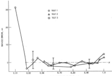
The dominant error source for the range meas urement is caused by the unknown reflectivity of the target, which results in a varying amplitude of the reflected light pulse. Angle of incidence also contributes to the intensity variations.
Measurement to an unknown target within 2 ern or better is possible with care. Unexpectedly small reflected light intensity (as from a very black target) causes larger errors. Adjustment of the constant-fraction discriminator is critical and must be maintained, although it has been found to be stable over periods of many days. Perturba tion of the shape of the photomultiplier pulse by cross-talk or ringing in the photodetector output circuit must be avoided in order to maintain stable discriminator performance.
The aforementioned errors caused by reflec tivity variation, also called "walk", are not fundamental in nature and are repeatable. They can be reduced by shortening the light pulse rise time, and can also be reduced if a better type of intensity-independent discriminator could be developed. Candidates for testing exist (Ref. 4), but to date we have not investigated them. Walk error could also be r educed by monitoring the intensity of the return light pulse and using it to compute a range correction. A plot of reflectivity errors, caused in part by an impe rfectly adjusted constant fraction discriminator, is provided in Fig. 3.
PEAK PHOTOMUlTIPllfl OUTPUT , voh1
Fig. 3. Change in Measured Range as a Func tion of Reflected Light Intensity
A second type of ranging error, caused by el ectroni c noise, is presently much smaller than the reflectivity walk error, but can become signif icant if a high data rate (approaching, for in stance, 100 points per second at a 2-meter range) is required . Range noise is caused by detector noise and, unlike walk, will have a zero average value.
ASSOCIATE;:> ROBOT SYSTEI1
Robot Description
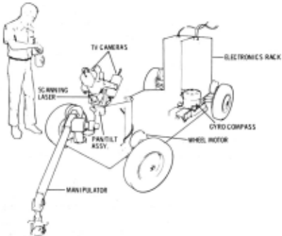
The robot (Fig. 4) consists of an integrated set of environmental sensors and effectors. The system is a breadboard, intended to provide a tool for testing various approaches to problem-solving and autonomous operation. The long-range con ceptual goal is an autonomous Martian roving vehicle able to make some independent dec is ions, gather the information required to make those deci sions, and act on those decisions, all in a manner consonant with broad mission goals. The major components are locomotion, manipulation, and vision systems.
LRF data is us ed by the path planning software in the generation of obstacle maps before the vehicle moves and, during motion, in providing a safety function.
The vision system includes the LRF, two TV cameras, and associated software. Th e carneras and LRF are mounted on a common pan-tilt head, approx imately 1. 2 rneters above the surface of t he vehicle. The basic task of the vision system is to detect and locate objects of interest and also obstacles to vehicle and manipulator motion. The dual TV carneras and the LRF combine to provide much redundant information. Various ways of utilizing the r edundancy in an advantageous way are currently being investigated.
Coordinate Frames
There are three coordinate frames relevant to laser operat~on (Fig. 5). The first is the ARM system, centered at the base of the manipulator on the ve!:licle's surface. The unit vectors of the ARM system point, respectively, across the vehicle
front (XA), in the direction of forward vehicle motion (Y A) , and up from the vehicle surface CtA).
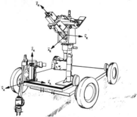
The second coordinate frame is the rotated ->- ->- ->- pan-tilt (RPT) system. Its three axes (~, YR' ZR) are aligned with the pan-tilt head's rotated posi tion and point, respectively, along the line of sight, tilt axis, and pan axis. This frame is centered at the laser, at the point where the beam would intersect the LRF mirror when th e instrurnent is at the "reset position". Tne reset position is the LRF azimuth/elevation setting that directs the beam along the line of sight of the pan-tilt head, the so-called "straig..'lt ahead" position.
The third coordinate frarne is the laser step (LST) system, centered at the reset position's beam-mirror intersection point. It is a spherical polar system, with its first two coordinates b eing integer stepper-motor step numbers related to azimuth (a) and elevation (E), respectively. Its third coordinate is a range null'her ( r) equivalent to the time of flight to target.
System-Related Effects Impacting LRF Performance
There are three rnaj or components to any evalu ation of the LRF as it performs in the total robot sys tern. The.se are vehicle-relative pointing accu racy, ranging accuracy, and external environment relative factors.
It has been found that the laser beam can be pointed with excellent repeatability. This is due in part to the fact that the beam cannot "rest" anywhere in its two-dimensional (azimuth, elevation) space, but only at the lattice points dictated by the incremental nature of the stepper motors. The pan-tilt head on which the laser is mounted is likewise an incremental subsystem. Thus it is that the beam can be repeatedly directed in the same physical direction whenever the four point ing variables (pan angle q,, tilt angle e, a, E) are repeated by command. This, of course, is one of the features enabling the recalibration process to function smoothly; the beam can reliably be directed to the same vehicle-fixed target points.
The accuracy of the beam direction relative to the vehicle is somewhat degraded. The position of the pan-tilt head, its alignment with the vehicle frame, and the orientation of the LRF azimuti1 and elevation axes relative to the pan-tilt assembly are only estimated. In particular, the "zero" pointing direction (pointing the beam in the direction of vehicle motion, parallel to the frame) is accurate only to an estimated half degree.
Another source of beam pointing error is vehicle sag. The platform on which the arm, pan tilt (including cameras and laser), and electronics rack are IWunted is a somewhat flexible frame. Tne platform sags slightly to varying degrees and in varying directions at different locations, thus affecting beam pointing.
Ranging inaccuracies have been described in an earlier section. Suffice it to say here that the net effect of errors in ·ranging is an inaccuracy in position estimates along the line of sight.
These error sources all affect the determina tion of position of an object in the environment. For precise position determination, all of the parameters of the transformations relating environ ment to instrument must be known. Slight errors in estimating displacements between the arm and pan tilt and also along the pan-tilt to the laser, as well as errors in ranging and pointing (due largely to vehicle sag) all affect the accuracy to which an object in the external environment can be sensed.
As .the applications presented below show, how ever, even with all these sources of error, signif icant use of the instrument can be and has been made.
SOFTWARE DESCRIPTION, ORGANIZATION, AND USER INTERFACES
The primary function of the laser software is to move the. laser to a specified point and then take a range reading. Moving the laser beam involves controlling the laser scan apparatus, picking a mode (~several points and take readings, or slew to one point and take a range reading there), possibly moving the pan-tilt head, and allowing for the target point to be specified in a number of coordinate systems. Beyond this, the software must combine these functions for the self-calibration procedure. In addition, the software allows for easy access to frequently used combinations of these basic functions. A number of control func tions allowing direct communication between the user and the electronics are provided, and stat us and error indication flags are always returned.
The elementary control functions include an azimuth slew (move instrument to specified azimuth, take and return a range reading), an elevation slew, an azimuth scan (move instrument from present posi tion to new azimuth, taking readings at each point along the way, and, if requested, use DMA input), an elevation scan, an azimuth reset, and an eleva tion reset · The resets not only move the inst ru ment to its zero position, but in addition clear the device after "skip-step" errors so that accu rate beam pointing readings (a,E) can be assured. Other control functions permit the electronics to be reset (cleared and initialized) and various tests (scan busy, power on, data ready) to be performed.
Several composite functions are made easily available to the user. The simplest of these is the beam reset function, which resets both azimuth and elevation. A second function slews the laser to the specified laser step (a,E) and takes n range readings. The average range numberr is returned. If n > 1, then the variance of the readings is also returned.
The third set of functions reads the pan-tilt head or moves it to a specified (q, ,0). Each time the pan-tilt head is moved, the appropriate trans formation is recalculated and saved for future use.
The fourth function provided is the self calibration procedure. Here, the pan-tilt head is moved to a prespecified location, and 50 range readings are taken at each of two calibration points. The pan-tilt assembly is then restored to its precalibration position and the laser is reset, ready for use.
An initializing command to the LRF software sets an automatic self-calibration time interval. Thermal drift necessitates periodic recalibration. The automatic (i.e., time-dependent) recalibrating can be suppressed in order that recalibration only be done when specifically requested.
The fifth function performed by the LRF soft ware is coordinate transformation. A vector in any of the frames LST, RPT, or ARM can be re-expressed in any other of these three frames.
The sixth function is the scanning of a line. The line endpoints can be expressed in any of the three coordinate frames, and the repointing of the pan-tilt assembly to the center of the line can be requested as an option as welL The LST (c:t, E) and associated ARM (X, Y, Z) are returned for each scanned point. The scanning procedure generates a sequence of lattice points (Recall that (a,E) are restricted to the integers, as stepper motors are used to drive the laser) which most closely follows the desired line.
The final function made available as an integral part of the software package is the "stop"
function, which terminates the program after closing the mirror completely. The mirror is closed to avoid dust and scratches when the apparatus is not in use.
The software performing these functions, as all the laser software, is coded in Fortran and assembly language on the General Automation SPC 16-85. The basic software package described above runs in less than 6K of core. This software is made available as a subroutine (LRF) to other users, and also has been combined with two supple mental functions and a teletype driver for stand alone use,
The supplemental functions are a rectangle scan and a vehicle obstacle scan. The rectangle scan works like the line scan, accepting four cor ners expressed in any of the three coordinate frames. Up to 20 parallel lines spanning the rectangle are scanned, and the highest (maximum Z in arm coordinates) point is saved, It is assumed that the highest point is part of a rock, and the area about that point is (re-)scanned to determine the rock's orientation. The rock's position and orientation are then output to a file. This rectangle scan has been combined with the manipulator software to yield an end-to-end demonstration of integrated laser-manipulator operation.
The second supplemental function provided with the teletype driver is an obstacle scan at 3 meters in front of the vehicle. Here the beam is swept side .to side in an effort to locate severe adjacent-point range differences. If one is located, a single bit is returned to the vehicle drive software.
All calls to the laser software result in an error/status flag being returned to the caller (or teletype). This flag reports violations of laser azimuth or elevation limits, laser drive step skipping (which would result in the beam position ( ex , e:) being unknown), range numbers (r) out of the domain of possibility (for example, because the power supply is off or because no reflected light pulse is returned), pan-tilt errors, and warnings that conversions to LST coordinates are out of the acceptable domain of operation.
APPLICATIONS
The LRF software has been made operational and available to the Robot Research Program as a package only relatively recently, Nevertheless, the LRF instrument and software have already been applied to several tasks, with more currently being investigated. In this section, these applications are described.
Rockfinding
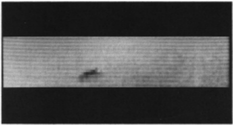
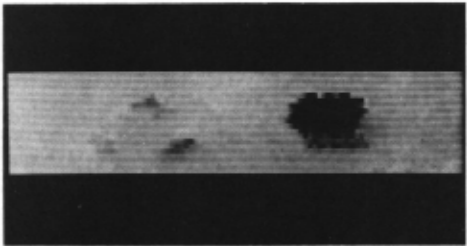
The rectangle scan described above as the first supplemental function has been combined with the manipulator software to yield automatic scan ning, recognition, position and orientation deter mination, and retrieval of the tallest rock in a 30 em x 70 em scanned region. The elevation of the scanned points is displayed as intensity data on a video monitor, as shown in Fig. 6. Higher points appear darker on the displayed image. The range data is converted to ARM coordinates, the Z coordi nate of which is converted to an integer corre sponding to an intensity datum on the monitor.
(a)
(b)
Fig. 6. LRF-Generated Elevation Pi c ture of (a) A Rock and (b) Three Rocks and a Block (Higher points displayed as darker)
Errors in the end-to-end sequence include all laser and pan-tilt pointing errors, laser ranging errors, vehicle sag and other transformation errors, and arm positioning and calibration errors. In essentially all cases, the laser instrument and. algorithm precision are sufficient for the rock to be recognized and located by a laser beam aimed at it, but only in about half the cases to date are the position and orientation data, transformations, and arm positioning and calibration accurate enough to result in the target rock being successfully retrieved and deposited in a sample box. Continuing work on the use of arm-mounted proximity sensors as grasping aids (Ref. 2) is expected to result in a much higher success rate.
Vehicle Obstacle Scan
The side-to-side laser scan described above as the second supplemental function is to be used as an in-motion early warning obstacle detector for vehi cle motion. The beam is swept along a line 3 meters in front of the vehicle at ground level, from the outside of one wheel to the outside of the other, back and forth. No coordinate transforming of the raw data is performed, but rather, sharp differ ences in the raw range data themselves are sought. Figure 7 graphically illustrates the returned range data when no obstacle is present and when a three inch high box is present. The criterion for an obstacle currently being used is a range differ ence of 7.8 em or greater between successive points, If this criterion is met, a flag is returned to the vehicle drive program, which can then stop the AZIMUTH STEP a vehicle, gather more data about the obstacle and surrounding environment, and plan a new path.
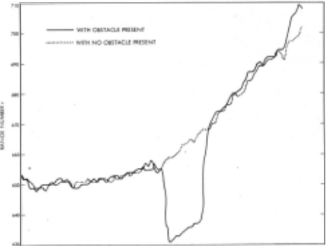
Fig. 7. Vehicle Obstacle Scan LRF Data
The present vehicle is he avy relative to the power available to drive it, so that even an 8 em object is an obstacle. Range differences do not correspond directly to differences in elevation, and it is conceivable that an obstacle with smooth edges and no real corners could r emain undetected. The described scan algorithm and obstacle criterion thus represent a compromise between simplicity (and speed) of operation, on the one hand, and effec tiveness on the other.
Another factor that tends to diminish the thoroughness of the scan is the effect of vehicle motion. A scan takes about 2 seconds (94 points at 50 points/second). By moving the vehicle slowly in areas of more danger or less, complete knowledge of the environment, and by comparing detected obstacles with objects already known (see below), the laser in-motion obstacle scan is expected to be a useful adjunct to the .robot's safety system.
Obstacle l1apping
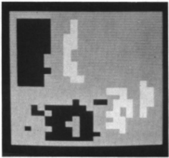
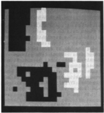
The first user application to whi ch the laser system has been put is obstacle mapping. Before the vehicle is moved, a t errain map of the area must be obtained. A single television image could be used for this purpose, but then the information obtained is only two-dimensional; its location along the line of sight would remain unknown. Tele vision images from two cameras or from the same camera at two locations could provide three dimensio.nal data, but only at the expense of corre lating the video data from the two images. Accord ingly, the LRF, which provides three-dimensional data from a single "image", has been used to map the terrain in the vicinity of the vehicle. Fig ure 8 shows a processed terrain map of a 3-meter square in front of the vehicle. "Safe" (i.e., obstacle-free) regions are shown in gray, unsafe ones (those whose elevation is 15 em or more from the floor, as defined by the vehicle wheelbase) in white, and unknown regions in the shadow of obsta cles in black. The lower obstacle map in Fig. 8 shows a processed version of the upper map in which adjacent obstacles have been merged. A series of
(a)
(b)
Fig. 8. Obstacle l1ap (Safe regions shown in gray, unsafe in white, and unknown in black)
t errain maps covering the area between vehicle and target is made, after which the terrain can be searched for a safe path.
Range Pictures
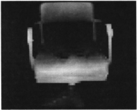
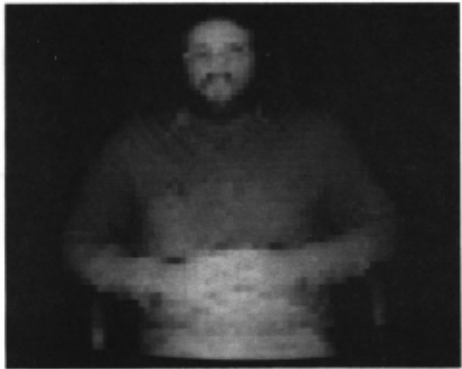
The LRF is quite sensitive to changes in range. A demonstration of its s ensitivity and ability to yield data of sufficient quality for scene analysis work is presented in Figs. 9 and 10. These figures are "rangepics". Range data (integers from 0 to 1023) have been converted to intensity data (0 to 255) and displayed on a video monitor. The pi c tured features are approximately 2 to 3 neters in front of the vehicle. The laser data were taken over a complete lattice of 64 x 64 LRF azimuths and elevations. As displayed, no correction for angular distortion has been made. The box-like structures in the images result from the fact that each laser datum is displayed as a 4 x 4 array of monitor pixels in order to fill the screen.
Picture Segmentation and Scene Analysis
The application of scene analysis software designed for video data to LRF data is currently being investigated. The straightforward segmenta tion of laser rangepics is one approach being con sidered. Aiming the LRF at specified video image points for range data or dual camera image matching, tracking of the laser beam as it moves through a visual scene, and using the laser to confirm the existence of edges and object boundaries are other avenues being considered. It is antici pated that the dual TV/LRF system will ultimately provide the JPL robot with a powerful perceptive apparatus.
SUMMARY
A scanning laser rangefinder for a robotic vehicle has been described. Its ranging accuracy approaches 2 em with optimum adjustment. The dominant error source is the effect of unknown reflectivity and angle of incidence of the target surface. Pointing accuracy of the instrument itself is well within 0.1 deg, a small error compared to the range error. However, the cumulative effects or errors induced by mounting the LRF on a pan-tilt assembly, putting the entire apparatus on a vehicle, and then relating the results to the environment also tend to degrade the performance of the LRF.
We feel that the instrument could be improved significantly with further development effort. First, current semiconductor techniques appear capable of reducing the risetime of the light pulse significantly, and since the accuracy at present is directly dependent on risetime, this would be a practical benefit. Improvement may result even though the peak pulse power may decrease, if pulse repetition rate and risetime can both be improved.
A second approach, independent of the light pulse shape, involves improvement of the timing decision through more effective fast pulse elec tronics. Such improvement could be obtained by performing a measurement of the reflected pulse height and using the information to correct meas ured range. A conventional intensity image as seen under illumination by the LRF itself could be obtained as a by-product.
Alternatively, better schemes for timing independent of intensity could be sought, either in terms of improved constant-fraction discrimination, or by means of multiple data points from each pulse (Ref. 3), the ultimate being a real-time cross correlation.
At present, the LRF is not driven by any requirement for a high data rate, and indeed, its data rate is very low. Efforts to increase the data rate will encounter a limitation due to basic noise in the detected signal at about 100 data points per second, with the present laser power. Higher data rate will involve a tradeoff in which uncertainty of a single point increas es proportion ately to the square root of data rate.
Even as the system stands today, numerous practical applications have already been made and more continue to be investigated. The results of these investigations will be reported as the con tinuing integration of the LRF and its software with vehicle and vision systems progresses.
@inproceedings{ijcai1977p182,
  title     = {A Scanning Laser Rangefinder for a Robotic Vechicle},
  author    = {Lewis, R. A. and Johnston, A. R.},
  booktitle = {Proceedings of the Fifth International Joint Conference on
               Artificial Intelligence, {IJCAI-77}},
  publisher = {International Joint Conferences on Artificial Intelligence},
  editor    = {Raj Reddy},
  pages     = {762--767},
  year      = {1977},
  note      = {Robotics},
  url       = {https://ijcai.org/proceedings/1977/182},
}
TY - CPAPER TI - A Scanning Laser Rangefinder for a Robotic Vechicle AU - Lewis, R. A. AU - Johnston, A. R. T2 - Proceedings of the Fifth International Joint Conference on Artificial Intelligence, IJCAI-77 PB - International Joint Conferences on Artificial Intelligence PY - 1977 SP - 762 EP - 767 UR - https://ijcai.org/proceedings/1977/182 ER -Copied
Machine-readable versions of this paper, for tools and AI agents:
 Welcome
 Future Conferences
 AI Journal Division
 IJCAI Proceedings
 About IJCAI
 IJCAI Awards