
A Practical Manipulator System
Proceedings of the Fifth International Joint Conference on Artificial Intelligence. Robotics. Pages 723-731.
© 1977 International Joint Conferences on Artificial Intelligence
Abstract
This paper describes the development of a practi c al manipulator system. The manipulator requ ir ements dictated by space exploration, the functional elements which meet those requirements, and the problems encountered in implementing those requirements are discussed. The paper focuses primarily on the implementation of the functional elements and the real world problems encountered by the manipulator system, as opposed to the specific algorithms and equations, since we feel that these two factors are underemphasized in the literature. Specific topics discussed include user interfaces, trajectory planning, safety and obstacle avoidance, and link motion control. Impl ementation emphasis has been placed on flexibility, minimizing complexity, and increasing reliability.
- Dobrotin, B. M., Scheinman, V. D.; " Design of a Computer Controlled Manipulator," Third Annual Joint Conference on Artificial Intelli- gence ; Stanford, Calif., Aug. 1973.
- Lewis, R. A.; "Practical Manipulator Soft- ware;" Milwaukee Symposium on Automatic Computation and Control, Milwaukee, Wiscon- sin, Apr. _1976.
- Lewis, R. A.; "Autonomous Manipulation on a Robot;" JPL TM 33-679, Jet Propulsion Labor- atory, Pasadena, Calif.
- Paul, Richard; "Trajectory Control of a Com- puter Arm;" Second Annual Joint Conference on Artificial Intelligence, London, England, Sept. 1971. IJCAI
- Johnston, A. R.; "Optical Proximity S ensors for Manipulators;" JPL TM 33-612, Jet Propul- sion Laboratory, Pasadena, Calif.
- Bejc zy, A. K. ; "Environment Sensititive Mani- pulator Control;" IEEE Con£. on Decision and Control, Phoenix, Ariz., 1 974 .
- Markiewicz, B. R.; "Analysis of Drive Meth- ods for a Manipulator;" JPL TM 33-601, Jet Prop. Lab. , Pasadena, Calif.
- Lewis, R. A., Bejczy, A. K.; "Planning Con- siderations for a Roving Robot with Arm;" Third Annual Joint Conference on Artificial Intelligence, Stanford, Calif. , 1973. Rohotics-1: nohrntln IJCAI
References were extracted automatically from the PDF and may contain errors.
Full text extracted automatically from the PDF; figures, tables and equations may differ. The PDF is the version of record.
Introduction
The Jet Propulsion Laboratory has been work ing for several years in robotics as a means of extending space exploration. Increasing task com plexity and longer telecommunications delays have been making space exploration requirements more severe, as demonstrated by the recent Viking mis sion where several days were needed to move a rock. JPL has started to apply robotics in sup port of future space missions, including both Earth orbiting missions and deep space explora tion. The advantages sought are reduced cost in both time and money.
Several missions which would benefit from advanced manipulation capabilities have been iden tified. These missions include surface roving, assembly of large structures in Earth orbit, and servicing Earth orbiters beyond the reach of the Space Shuttle. These types of missions are being planned for the 1980's and 1990's. and have increas ingly complex needs. The most immediate mission would be a Mars rover performing limited tasks such as cleaning dust from lenses and soil sampl ing, while missions requiring precision assembly of large beams are further in the future.
Both the ability to control a manipulator and integration of manipulation with other capabilities
A PRACTICAL MANIPULATOR SYSTEM*
Boris Dobrotin Richard Lewis Guidance and Control Section Jet Propulsion Laboratory California Institute of Technology Pasadena, California
such as locomotion and vision must be provided. For this reason JPL has developed a breadboard roving vehicle (rover) which uses the three basic functions of manipulation, locomotion and vision (Fig. 1). The manipulator has been developed as an integral part of the JPL rover.
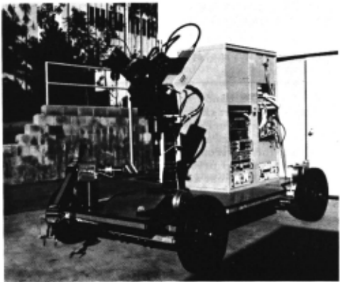
Development Goals
As mentioned above, manipulation tasks are established by space mission needs and may be divided into two categories : assembly and sample handling. Each task has a different set of require ments, as briefly characterized in Table I.
Assembly tasks require precision of motion in the range of 0. l mm to l em, the ability to con trol forces and torques, and external feedback such as force sensing. In general, the environ ment and the equipment the manipulator is work ing with are well known, though not precisely positioned. An analogy may be drawn with an industrial environment, where assembly consists of joining precisely fabricated pieces whose loca tion (but not orientation) is generally known. Such a task depends primarily on specialized sensory feedback with vision performing only a supervi sory function.
*This work. represents one phase of research carried out at the Jet Propulsion Laboratory, California Institute of Technology, under contract No. NAS 7-100, sponsored by the National Aeronautics and Space Administration.
| Assembly Task | Sample Handling Task |
|---|---|
| Subtasks | |
| Large structural element assembly | Rock sample retrieval |
| Precision instrument assembly | Trenching Digging |
| Spacecraft module servicing | Rover servicing |
| Requirements | |
| Precision motion | Vision feedback |
| Small scale detailed environmental information | Environmental interaction |
| Force, torque control Use of a priori knowl edge of work area | Development of own knowledge of work area |
On the other hand, a manipulator performing sample handling tasks on a planetary surface operates in a different environment . Task defini tion is straightforward, (i . e., move rocks, dig soil), but the environment is unstructured and cannot be detailed prior to arrival at the site. The spacecraft must accommodate a wide variety of inputs with little a priori information. Though precision requirements are lower (1/2 em to 2 em), the task is more demanding since the mani pulator must cooperate closely with the vision system, and use its own feedback sensors. The problem becomes one of dealing with an unstruc tured real world environment , requiring the abil ity to generate and use a large data base.
Requirements
The JPL manipulator development used avail able components for both computing and manipulator-specific hardware. The intent was to develop techniques for manipulation tasks , rather than a specific manipulator mechanization. As a result, specification development proceeded concurrently with manipulator development until a final set of requirements were established which were suitable for the tasks in Table I .
The general requirements are summarized in Table II, and represent development requirements which establish goals. They do not represent a summary of specific requirements needed for actual spacecraft operation, but rather are those needed to demonstrate the technology required. For example , once assembly technology is demon strated, a mission-specific manipulator may be designed to handle 25 to 50 Kg beams for struc ture assembly in Earth orbit . The requirements shown in Table II represent those qualities needed for both assembly and sample handling tasks.
The first requirement is for the environment in which the manipulator must operate . The en vironment has both a known component (the rover surface which constitutes the upper level of the manipulator work surface has fixed, known ob stacles) and a randomly varying component (the surface upon which the rover moves) . Thus the manipulator can have "built in" knowledge to ease the task of trajectory planning, but must alsobe able to receive and respond to information .on the changing environment.
| Factor | Parameter |
|---|---|
| I. Environment | |
| On vehicle | Known, varying |
| On work surface | Unknown, random |
| Sensing | Distance, pressure, size |
| II. Workspace Coverage | |
| Volume | 3 / 4 hemisphere, 4 ' dia, bilevel work surface |
| Obstacles | 30o/o of workspace vol ume randomly spaced, varying |
| III. Computing | |
| Computer | On Line - 16K active 1 fLsec/cycle |
| Input/Output | A/d, DAC single point 3 Megabaud-sensors to computer, 1600 baud computer to user |
| IV. Interfaces | |
| Mounting | Rover |
| Users | Three on line and off-line computers |
| Rover subsystems | Vision, locomotion |
| V. Motion | |
| Speed | Point-to-point cover age <5 sec. Planning < 10 sec. |
| Precis ion | <0. 1 mm |
This realtime information can be supplied by the vision system, but some direct information on the manipulator's state relative to the environ ment (including a sense of distance to an object as well as a sense of touch) is also needed .
The workspace requirement is dictated by both the geometry of the vehicle and the work to be performed, The manipulator must be able to work on both the vehicle and a reasonable ground area. Obstacles may occupy up to 30o/o of the volume, and, while those on the vehicle are known, those on the ground have randomly vary ing size, shape and location.
The computing facilities provided consist of a minicomputer, a General Automation SPC-16/85 (SPC 16) with direct I/0 to the sensors and actua tors in the electromechanical assembly (E -M assembly.) A low speed communication line from the minicomputer to the off-line computer (a DEC PDP-10) provides the main data link with the vision and locomotion subsystems. The main computing requirement was to work within the minicomputer with only limited data from the other subsystems.
A user interface to the manipulator system is required at several levels: to the on-line mini computer (for checkout), the off line computer. (for integration into the rover system), and to a graphics terminal (us ed to display the internal rover state). All interfaces must supply data on the manipulator's state as well as accept opera tional commands.
Manipulator response time requirements were initially arbitrary and primarily aimed at reducing the operator's wait time. The prime motion con trol requirement is in precision motion control during both midtrajectory and terminal placement phases. ·
Functional Elements
The manipulator system can be thought of as consisting of the E-M assembly, its electronics and interface to the SPC 16 and the manipulator software contained in that computer. The hard ware is described in Re f. 1 with the software summarized in Ref. 2 . Figure 2 is a block dia gram of the manipulator's functional elements .
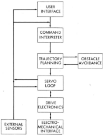
The first element is the user interface, which both accepts commands and data from the various users and supplies manipulator status data. The commands then go to the command interpreter which decodes them and provides the necessary sequencing and data for the trajectory planner.
The trajectory planner takes the desired target point of the manipulator hand and provides angle versus time trajectories for the individual links. The trajectory planner works in conjunction with the safety system to detect possible collisions between the manipulator links and obstacles.
The servo loops are responsible for controlling the motion of each link so that each planned tra jectory is followed. The servo loop controls the DC motors in the E-M assembly through the am plifiers and conversion equipment which make up the drive electronics .
User Interfaces
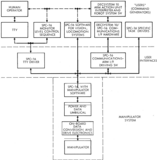
The entire manipulator system resides in the JPL Robot Research Laboratory. The software totally resides in the SPC 1.6 which is dedicated to the robot. Manipulator-related software in the SPC 16 serves to interface specific users with the manipulator system. Users include human opera tors directly interfacing with the SPC-16, prede termined sequences of actions input as SPC-16 monitor level commands, other robot systems (i. e. , vision system) acting through SPC 16-con tained software, and the Robot Executive (REX) and other robot system software contained in the remote time shared PDP-1 0 as well as the Proto type Ground System associated with an Imlac gra phic display unit. Data flow through the manipu lator system, with particular emphasis on the user interfaces is shown in Fig. 3.
The manipulator software has been designed to permit access by a wide variety of users. Writ ten in Fortran and assembly language and using approximately 10, 000 words of core, it consists of a collection of operating subroutines and a single "main subroutine" communicating with all users. The total collection of subroutines has only a single entry point and a single exit point, both in the main subroutine. The lack of multiple entry points and the funneling of all input (com mands and arguments) and output (feedback to user) through the same main subroutine, inde pendent of user, have facilitated program check out and maintenance, in that all users operate the system with the identical software. The operating subroutines perform the functions described be low (including planning, obstacle detection, coor dinate transformations, and a large part of the motion control).
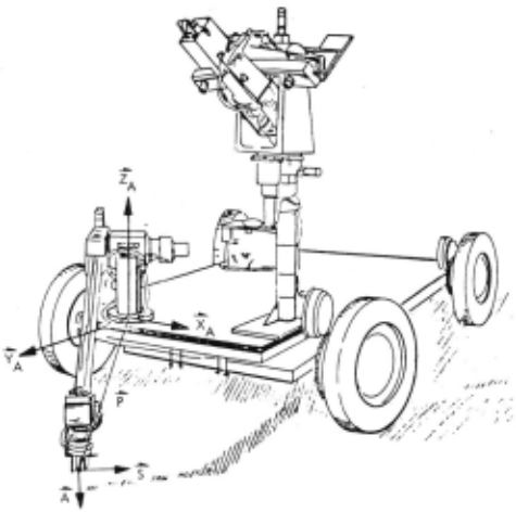
Input to the manipulator system consists of an integer command and an eighteen-word argument array. Feedback from the system to the user is given via the argument array. The array on re turn contains the six joint variables_ll.nd the finger opening, the arm's position vector _p, finger slid ing vectorS, and approach vector A (Fig. 4), tac tile sensor readings (from 2 microswitches), and an error indicator. The error indicator shows errors in planning (i.e., a collision would occur) as well as execution as shown below. Command arguments are provided by modification of the appropriate array elements. The commands themselves allow for the performance of the following functions: system reinitialization and status, open fingers, close fingers, move arm to specified position with specified or default hand orientation, move all joints to specified values, move single joint by specified amoun~ tran~orm coordinates {joint variable values to P, "'t, A and back), squeeze fingers, weigh object, change speed, center fingers using proximity sensor feedback, and terminate execution.
The Robot System software, contained in the PDP-10, allows for the execution of plans. Plans consist of action units, which are sequences ap plicable to manipulation, vision, or locomotion systems, with symbolic arguments referring to named data in a World Model, An action unit in terpreter converts action units and their symbolic arguments into the manipulator system commands outlined above. All manipulator action units are in one of five categories: data/status action units {including the storage, delection, and modification of World Model data), boundary action units be g inning and ending the operation of the manipulator system, speed action units for altering the time taken by arm motions, finger commands (open, close, squeeze, center fingers over object using proximity sensor feedback), and arm motion ac tion units (move to, move by, move joint(s), drop, weigh, display to TV).
All users interface with the manipulator system via the main subroutine in the SPC 16. Other robot systems or any of the specific task drivers (which are all SPC 16 main programs) call the manipulator system as a subroutine. Other robot systems can also interface with the manipulator system by ordering the execution of arm action units; in this case , the PDP-10 resident robot software communicates to a SPC-16 resident com munications program that calls the manipulator system as a subroutine. The other interface to the manipulator system is via a teletype driver. With this main program, a human operator sta tioned at a console or an existing monitor-level control sequence can control the manipulator sys tem. In all cases, it is the identical manipulator system with which the user interacts.
Planning
Motion planning in the manipulator system is minimal. Target position/orientation or changes in position/orientation are transformed to changes in joint variables. All links beg in and end motion simultaneously, with the duration of motion deter mined by scaling with respect to the maximum allowed velocity for the slowest link. It is the maximum-allowed-velocity vector on which the speed change command acts . All joints are then moved according to a single normalized polyno mial (Re f 3, 4).
where g increases monotonically from 0 to l and has 0 first and second derivatives at the boundary points. Thus, the arm moves from one r est posi tion to another, without changing direction. The monotonicity of the polynomial guarantees that if the boundary points are within the allowable range of motion for each joint, then so are all inter mediate points.
The entire path of each link and hence of the arm is thus planned. The path is checked at planning time for potential collisions with obsta cles . Potential collisions are avoided by the operator inserting safe intermediate points and then decomposing the original motion into se quences of motions connecting the intermediate points.
Aside from limitations on the ranges of motion of the joints, the JPL manipulator must also con tend with twelve permanent obstacles. These in clude the vehicle platform, an electronics rack, the wheels ·and wheel motors, the television/laser rangefinder assembly, and the ground . Each of these obstacles is described by the circumscribing rectangular envelope with sides a ligned with the manipulator base coordinate system. Thus, all obstacle data are stored in ann x 6 array, q, (n = number of obstacles), where each row of q, is of the form (Xmin· JSrnax, Y min· Y max· Zmin· Zmax· ). A point P = (Pl, P2, P3) is within the boundaries of obstacle i if it lies within the obsta cle i rectangular solid, that is, if
A more obstacle-specific characterization would permit a greater range of manipulator motion by more accurately describing the obstacle, but at the cost of lengthier and less verifiable software. The description of an obstacle by two or more rectangular solids and using the rectangular enve lope as a preliminary check only are two ways of obtaining increased accuracy while still maintain ing software efficiency and verifiability.
Each trajectory is decomposed into a sequence of specific arm positions, and potential collisions are considered at each of these positions. At present, we check for collisions at twenty points along the trajectory.
The JPL manipulator has two links, the sliding boom and the wrist/hand assembly, that are cap able of collision. Each of these is represented as a line:
where B ("back" ) and F ("front" ) are the endpoint of the line parameterized by~. The collision de tection algorithm works through the obstacle ar ray lj>, dimension by dimension, and finds the limiting values of ~necessary for collision. If there exists a ~E Lo, 1] satisfying
for j = 1, 2, 3, then a collision can occur and the motion is aborted. Otherwise the motion is safe for that link Pat that point of the trajectory with respect to obstacle i.
Nonpermanent obstacles detected by the robot environment sensors are added to the obstacle array; the collision detection software remains unchanged.
Each time the arm is to be moved, the path is checked for potential collisions. If one exists, both the colliding link and the obstacle are identi fied, as well as at what point of the trajectory the collision would occur. This data is used in obsta cle avoidance in the gene ration of the intermediate points. At present, this must be done by the operator.
An alternative or pe rhaps supplemental method for the detection and avoidance of obstacles is cur rently being investigated. Optical proximity sen sors (Ref. 5), currently mounted on the fingertips as grasping aids, could be mounted at various points on the arm. Suitable arrangement of the sensors could provide enough information during arm motion not only to detect obstacles but also to suggest an avoidance strategy. It is estimated that fifteen sensors would be required to perform. the task completely. If implemented, the mani pulator would be equipped with a reflexive obsta cle avoidance system acting in real time and with out any a priori information about the obstacle environment. Difficulties in achieving this include wiring the arm for all the sensors, implementing a hardwired control system response to proximity sensor feedback to override the general control system, and integrating the two control systems. Early experiments in reflexive obstacle avoidance (Ref. 6) have, however, indicated the theoretical feasibility of such a system.
Position Control System
The manipulator position control system is used to servo the positions of individual links dur ing manipulator trajectory execution and to gener ate forces during assembly tasks. It must provide accurate control during motion as well as precise positioning at the end of motion. In addition, it must operate over a wide range of system param eters (inertia and friction) while rejecting extran eous input (e. g., noise).
The manipulator servo system used is shown in Fig. 5, with a simplified block diagram in Fig. 6. It is a sample data control system using analog feedback sensors and current drive to the D-C motors. The servo system is identical for all six manipulator links, while the "hand" servo loop is driven by a fixed current command.
The block diagram in Fig. 6 illustrates the form of the present servo loop which is simpler than the loop initially used (Ref. 7). Gain con stants are used in the forward loop as well as each fe edback loop to normalize the various gains of the buffer amplifiers, converters, motors, etc. (Gl, G4, G6). This allows the servo loop to be parameterized by the servo loop gains; position error (Kp), position error integral (Kpi), velo city (Kv), and velocity integral (Kpi), as shown in Fig. 6. This permits one set of gains to be cal culated for all six servo loops, each of which will have the same theoretical response.
Gain selection was guided by two requirements: first, to eliminate final position offsets for fric tion and gravity torques and, second, to minimize position lag during trajectory motion. The second requirement is especially important for safe collision-free motions.
An initial estimate of the servo loop's perfor mance may be made using linear analog techniques. The sample data feature may be ignored due to the high sample rate (125 Hz). The two cases of interest are the response to· 1) input commands and 2) friction and disturbance torques. In each case a system transfer function may be deter mined from Fig. 6. For an input command the transfer function is given by G 9 = Motor ga in The four gains can be adjusted to provide good response to various inputs (step, ramp, etc.), and the control system as shown by the tr;;tnsfer function has the ability to closely follow the tra jectory polynomials discussed above. Although the effect of off-nominal gains due to changes in inertia, motor torque constants and feedback ele ments directly affects the loops gains, experience shows that these variations are minimal.

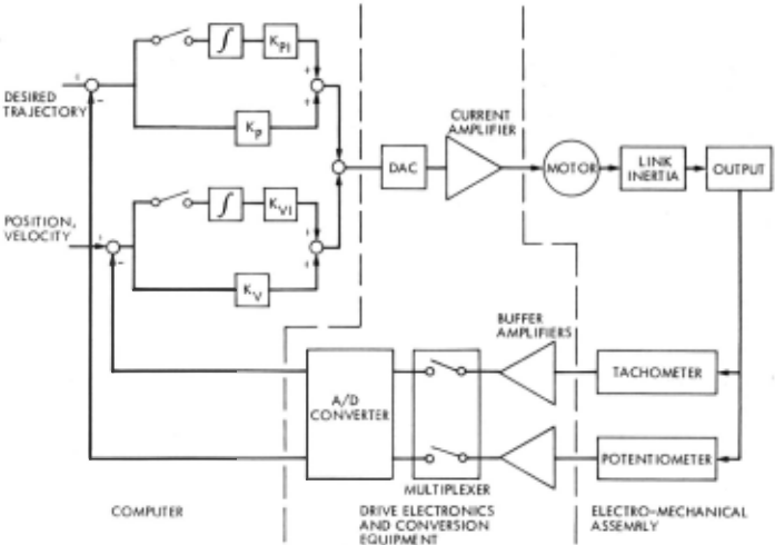
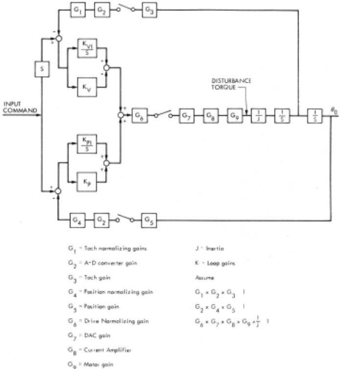
Fig. 6. Servo Block Diagram
Just as important as the ability to follow an input trajectory is the ability to respond to the effect of disturbance torques, primarily friction. The closed loop transfer function for a disturbance torque is:

Using these linear approximations, the follow ing conclusions may be drawn: for a step input disturbance torque the final falue of 8 0 will be zero, and increasing K,..,I d ec reases the transient response to disturbing forques (i.e., friction).
Thus several criteria become available for selecting gains. Without violating stability re quirements, high position gains (Kp + Kvi) are needed for accurately following the desired tra jectory. Second, an integral position gain (K I) is needed to eliminate standoff errors due to fric tion, gravity, and other disturbance torques. This integral gain should be as large as possible to minimize the effects of varying disturbance torques.
Terminal Guidance
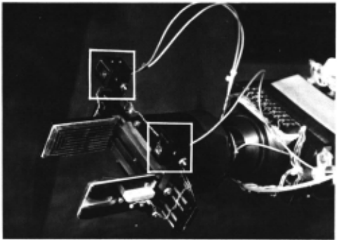
The phrase "terminal guidance" refers to the control of the manipulator in the neighborhood of some goal state. Three basic approaches are taken by the manipulator system in implementing this function. First, as the arm approaches an object, an intermediate point removed from the target along the <!,!rection of the final desired approach vector A (Fig. 4) is inserted. This guarantees that the hand will approach the target from the proper direction, Second, the two wrist mounted proximity sensors (Fig. 7) can be us ed to search a small ne ighborhood of the environment to verify the presence of the target object and to 'center the hand over it. Third, the finger mounted tactile switches and the hand potentiom eter can be used to verify that an object of approxi mately the anticipated size has been grasped.
Real-World Problems
The above discussion outlines the basic opera tion of the manipulator in its present state. Pre sented below is a discussion of problem areas that were overcome during development, and some that still remain.
'Timeshared and Noncaptive Computers
At present, the entir e manipulator system is resident in the JPL Robot Research Laboratory and dedicated to the rove r. At one time, the system was structured in such a way that the PDP-10 was required to run the manipulator (Ref, 8 ). The difficulties in communicating with a dis tant noncaptive time shared computer with time varying system features, and long and variable >'ystem response rates , as well as a desire for gre<Jter reliability l ed us to put all manipulator softwa re in the local minicomputer. Demonstra tion, execution, testing, and debugging of the manipulator system is no longer dependent on such variables as loading of the PDP-10, noise in the data links between computers, or communication software modifications. It is always useful to re duce the number of critical elements in the system, possibly even at the expense of some loss of com puting power ,
Calibration
The manipulator has a potentiometer at each joint. To determine finge rtip position and orien tation, it is necessary to transform the joint angles to Cartesian coordinates; and to determine joint angles, it is required that the potentiometer joint angle relationship be known precisely. None of the potentiome ters on the manipulator's five rotary joints are strictly linear, though none is so nonlinear that a table look-up or higher order polynomial fit is required. Instead, for each joint, nine positions are accurately determined and associated with the nine corresponding poten tiometer readings. Conversion to joint variable values is then done using the eight line segments connecting the nine points.
The nine readings are taken at 45 deg. inter vals over the range of joint motion, Then the joint angle values corresponding to specified po tentiometer values are interpolated. All joints but the first can be turned so that a level can be used to verify the 45 deg. settings. Calibration of the first joint pres ents a problem, however. That joint is calibrated by carefully placing the arm in known positions with known orientations, transforming these back to joint angles, and com paring the resulting first joint positions with the observed potentiome t e r readings. The procedure only need be repeated each .time the arm is reas sembled after maintenance, The intricacy of the procedure required illustrates the importance of planning for r eal-world problems during design stages of development.
Position Control System
During development of the manipulator, one of the most important tasks became the selection of proper control loop servo gains in the presence of friction, backlash and nois e in the electrome chanical assembly and drive electronics, High gains were n eeded to assure good r esponse and precision, but led to noise problems.
For example, a variation of 3 fuiri in Link 1 joint angle when the boom is fully extended is 1 mm (0. 050 in) which is incompatible with preci sion assembly tasks. Therefore any position lag during motion or offset after trajectory completion cannot be tolerated.
The primary problem is friction which proved to have a large effect on control loop operation. Inves tigation showed static friction limited reso lution and running friction was the main e rror source during motion, Fig. 8 shows the r es ponse of the electro-mechanical assembly of joint 1 to a sinusoidal position input, using an analog con trol loop, and illustrates the effect of drive fric tion, The torque curve shows the current com mand to the drive motor. Since the command is in phase with the velocity it may be assumed that it represents drive friction, The torque record ing shows the friction charac teristic: static fric tion as the velocity pass e s through zero, a high frequency oscillation as the link rotates, with the friction torque increasing as the velocity increases ,
All the manipulator's rotary joints that are used to position the hand us e Harmonic Drive for gearing between the drive motor and the link. At a joint 1 fr equency of 0. 06 Hz at.± 0, 4 rad. the LINK I
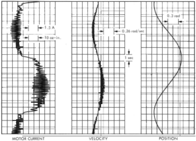
Fig. 8. Servo Respons e
running torque is 24 .±_ 5 oz-in, with a friction frequency of 5 Hz, as shown in Fig. 8. This friction frequency is identical to that expected of a Harmonic Drive, so that it is reasonable to assume that the friction is developed in the Har monic Drive. The Harmonic Drives used in the manipulator are the low backlash versions which have closer fits between the various parts. Tests with a torque gauge on joint 1 indicate that the Harmonic Drive has between 5 and 9 oz-in break out friction measured on the input shaft and ap proximately 600 oz-in measured at the output shaft. This corresponds to the breakout friction of joint 1 measured in Fig. 8.
Based on these friction levels, servo loop gains of Kv = 50, Kvr = 1000, Kp = 100 and Kpr = 5000 were selected. Initially, Kvi was not in cluded in the servo loop, but as Kp was increased, noise in the position feedback loop required either a digital filter or integration of the velocity error signal. Since the velocity error was directly available, it was used to provide the large noise free position error signal needed.
The 1arge value of Kpi is needed to minimize the effect of the friction disturbance torque (TF). As shown in Eq. (5) the output response to a sinu soid friction torque is inversely related to Kpi· In addition, a high Kvi is needed to assure good response. However, using high gain integrators in a servo loop with a deadband (friction or other wise) leads to limit cycles. This is particularly true in digital feedback loops, when a quantiza tion error is present. And indeed, with the gains mentioned· above, Link 1 will oscillate <.~bout+ 3/40 at between 1-3Hz. This is equivalent to + 0. 2 em at maximum extension which is com pletely unacceptable. The solution used is to switch off the input to these integrators, retaining the integral error, and at the same time increas ing the position gain to compensate for the loss in loop gain.
Removing Kpl will produce a static bias error of TF/ JKp· Tnis bias error may be satisfactory for some motions, i.e., linear motions with no absolute reference. However, other solutions can give better performance. First, an obvious solu tion is to reduce breakout and running friction in the Harmonic Drives. One possible approach would be to use standard backlash Harmonic Drives. Since mechanical backlash has not been a problem with the manipulator, the small amount of "wind-up" backlash present in the standard Har monic Drives should have negligible effect. In deed, minimizing the drive friction by whatever the m eans, would eliminate a whole cascade of problems and should have high priority in any manipulator design. However, the 6 oz-in break out friction measured on Link 1 represents only So/o of the available torque from the Link l drive motor and about l-1/2 amp of drive current, which is a very low level of disturbance torque.
An approach toward minimizing the effect of friction is to provide higher gain alternates to the link potentiometer feedback signal. Thus, sensors such as the force/torque sensors, added to in crease the manipulator's capability to operate autonomously, also provide high gain feedback with minimum noise. The force/torque sensor works on external contact forces, giving a high input gain to the position servo. When such sen sors are used to measure external data, the sen sor must be placed as close to the external source of information as possible, and the information should be used to drive the links with the least sensitivity to error, i.e., the outer links.
During build-up of the electro -mechanical as sembly, maximum effort was made to minimize electrical noise, This essentially consisted of separate shielding for all power and signal cables, as well as separate power supplies and grounds for all power and signal circuits. However, dur ing assembly of the rover, it also became appar ent that the same care had to be taken with each component and subsystem. This was difficult since each subsystem was developed by a separate group (vehicle, vision, etc .) not following identi cal grounding rules. Once the rover was assem bled, all power, signal and digital grounds had to be rewired and separated to bring electrical noise within acceptable limits.
An additional source of noise was found to be the pulse width modulated drive circuit for the vehicle motors. The high, pulsed currents would introduce noise into the digital circuitry. For ex perimental equipment where power effie iency is not a prime requirement, analog motor drive cir cuits give less system problems, as well as smal ler motion.
Summary and Conclusions
A practical manipulator system, integrated with the JPL Robot, has been described, The manipulator system is a general one, applicable to a wide variety of tasks and users and not specia lized for the achievement of any single ·manipula tion job. We have focused primarily on functional elements of the real world problems faced by the system rather than on specific algorithms and equations because it is tempting to bypass the former and because these factors appear to us to be underemphasized in the literature.
The functional elements described include user interfaces, planning, safety, control, and terminal guidance , Unique features of our implementation of these functions include flexibility of interfacing, the relatively small size of the software, and the speed and reliability of the obstacle detection method .
Among the real-world problems not fully ap preciated before their consideration was demanded by the system are noise, friction, backlash, in tercomputer data transfer, the vagaries of rely ing on a remote timeshared computer, sensor mounting, and calibration.
At present these problems have been largely overcome and the JPL manipulator is the robot's main element for interacting with the environment .
@inproceedings{ijcai1977p174,
  title     = {A Practical Manipulator System},
  author    = {Dobrotin, B. and Lewis, R. A.},
  booktitle = {Proceedings of the Fifth International Joint Conference on
               Artificial Intelligence, {IJCAI-77}},
  publisher = {International Joint Conferences on Artificial Intelligence},
  editor    = {Raj Reddy},
  pages     = {723--731},
  year      = {1977},
  note      = {Robotics},
  url       = {https://ijcai.org/proceedings/1977/174},
}
TY - CPAPER TI - A Practical Manipulator System AU - Dobrotin, B. AU - Lewis, R. A. T2 - Proceedings of the Fifth International Joint Conference on Artificial Intelligence, IJCAI-77 PB - International Joint Conferences on Artificial Intelligence PY - 1977 SP - 723 EP - 731 UR - https://ijcai.org/proceedings/1977/174 ER -Copied
Machine-readable versions of this paper, for tools and AI agents:





