
Force Control in Coordination of Two Arms
Proceedings of the Fifth International Joint Conference on Artificial Intelligence. Robotics. Pages 717-721.
© 1977 International Joint Conferences on Artificial Intelligence
Abstract
The use of two arms simplifies manipulatory tasks such as assembly of an object from large parts which cannot be handled by one arm. This paper describes the control method for coordination of two arms. As fundamental tasks, the parallel transfer task and the rotational transfer task are considered. More complex tasks are accomplished by using these two modes simultaneously. The control of motor torque of each joint is adopted instead of joint position control. The wrist force sensor Is used in order to measure the interactive force between two arms.
- R.C.Bolles, R.Paul, "The Use of Sensory Feedback in a Programmable Assembly System, " Stanford A.I.Project, Memo No.220, Oct.1973.
- R.P.Paul, "Modelling, Trajectory Caliculation and Servoing of a Computer Controlled Arm, " Stanford A.I.Project, Memo No.177, Mar.1973.
- T.O.Binford, D.D.Grossman, et al, "Exploratory study of Computer Integrated Assembly Systems, " Progress Report 3, Stanford A.I.Project, Memo No.285, Aug.1976.
- M.D.Roderick, "Discrete Control of a Robot Arm," Stanford A.I.Project, Memo No.287, Aug.1976. •
- H.lnoue, "Force Feedback in Precise Assembly Tasks," Massachusetts Institute of Technology A.I.Memo No.308, Aug.1974.
- J.L.Nevins, D.E.Whitney, S.N.Simunovic, "System Architecture for Assembly Machines, " The Charles Stark Draper Lab., Memo No.R-764, Nov.1973.
- C.A.Rosen, et al, "Exploratory Research in Advanced Automation," Stanford Research Institute Report, Jan.1976.
- A.K.Bejczy, "Robot Arm Dynamics and Control," California Institute of Technology, J.P.L.Memo TM33-669, Feb.l974.
- E.Nakano, T.lshida, et al, "Cooperational Control of a Pair of Anthromorphous Manipulators "MELARM", " Proc.4th lntern.Symp.lndustrial Robots, Nov.1974 . . rtohot i c: s -1: Ish i rl<J
References were extracted automatically from the PDF and may contain errors.
Full text extracted automatically from the PDF; figures, tables and equations may differ. The PDF is the version of record.
Tatsuzo Ishida Stanford Artificial Intelligence Laboratory Stanford, California USA
ABSTRACT
The use of two arms simplifies manipulatory tasks such as assembly of an object from large parts which cannot be handled by one arm. This paper describes the control method for coordination of two arms. As fundamental tasks, the parallel transfer task and the rotational transfer task are considered. More complex tasks are accomplished by using these two modes simultaneously. The control of motor torque of each joint is adopted instead of joint position control. The wrist force sensor Is used in order to measure the interactive force between two arms.
INTRODUCTION
Research with computer controlled manipulators Is becoming increasingly popular. Manipulation has remained an important area for studying the means by which intelligent systems control their world. Most of the problems of control in the real world must be faced In manipulation. Current systems make possible high-level tasks such · as putting a peg into a hole, assembly of a bearing complex and turning a crank by the use of force feedback. However, most work in the past has concerned the position control of single · manipulators. When we take a look at the actual human behavior of handling, we use two hands efficiently and skillfully, and are producing not only the simple quantative effect that the use of two hands does twice of the work by one hand, but also the qualitative effect that it makes possible tasks which are impossible to execute with one hand. Systems with one hand cannot carry out assemblies consisting of large parts which cannot be handled by one arm. In order to make possible more general assembly, two arms or more are necessary.
This paper describes the analysis of cooperative motion of two manipulators, using two Stanford arms which are available at the Stanford Artificial Intelligence Laboratory. External forces and the interactive force between two arms can be obtained by the use of the wrist force sensor which was recently installed.
Some new representation issues arise. While the bulk of earlier work was based on position representation, cooperation of two manipulators requires interaction which is expressed in a force representation. The servo requires force servo instead of position servo. Many manipulators have a hardware servo system which constitutes the position conrol system, but in the case of the Stanford arm a software servo system is adopted. Therefore it Is possible to program the manner in which feedback is to be used to modify the servo. The output command to each joint from the computer is the motor torque of each joint, so it is possible to control the torque of each joint. In the case that arms are influenced by the external forces such as In the coordination of two arms, the torque control system which can control the necessary torque of each joint is more effective than the position control system which outputs each joint angle position.
In this paper, as fundamental tasks, a method of evaluating the necessary torques to perform the parallel transfer and the rotational transfer of an object is presented. The analysis follows the classic decomposition of a general rigid body motion into a rotation and translation. Separate analyses are carried out for each. Rotations and translations provide simple and adequate models for motions. More complex transfer motion is possible by the use of these two modes simultaneously. For high performance, predictive control models become necessary, rather than simple feedback control. A next step, not considered in this work, is the modeling of the dynamics of the external world.
BASIC TASKS BY TWO ARMS
PARALLEL TRANSFER
When we consider cooperative tasks using two arms, such as the handling of a large box or a long bar, basic tasks can be separated into two tasks which are parallel transfer tasks and rotational tasks. In this section parallel transfer is considered. Parallel transfer means that the object is transferred maintaining the orientation of the two arms.
Before considering parallel transfer tasks, the interaction of two arms should be considered. There are two conditions on the relation of two arms. In the first, one of these two arms is supposed to work as a master arm and the other as a slave arm. The slave arm must be moved in cooperation with the master arm. In the second, these two arms work in the same status.
These two cases are described In the following.
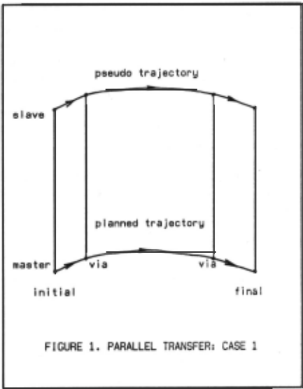
PARALLEL TRANSFER: CASE 1
In this case, we define two arms as a master arm and a slave arm. The master arm is controlled by the ordinary position feedback control with PID (proportional plus integral plus derivative) control and a feedforward term. For the master arm, the motor torque applied to each joint is

where
T(k)= command motor torque(oz-in)
8 (k)= actual joint position(deg) I
8 (k)= command joint position(deg) c
W 1 (k)=actual velocity (degjsec)
w (k)==command joint velocity(degjsec) c
a (k)=command joint acceleration(degjsec 2 ) c
J(k)= joint inertia(oz-in-sec 2 )
G(k)= joint gravity loading(oz-in)
F= joint friction with same sign as velocity(oz-ln)
K ,11. ,~<.,K = feedback coefficients p Y I C .
k= discrete time variable
When we can assume that two hands grasp the object firmly and that two hands and the object are supposed to be one body, the position of a point on the object is determined by 3 degrees of freedom of the master arm. Therefore the slave arm has to move completely following the motion of the object moved by the master arm, and cannot have degrees of freedom to the object. So the slave arm necessitates the good performance that it has gravity loading balance at arbitrary points and can be moved by the external force very lightly. For the slave arm, the motor torque applied to the upper 3 joints which decide the hand position is T(k)=J(k)a (k)+G(k)+F +L(k)+ Ti(k) c where
a (k)= command joint acceleration, which Is c calculated by supposing that the trajectory of the slave arm is parallel to
the planned trajectory of the· master arm. L(k)= joint loading, caused by the force applied to the object, if the force to the object is necessary.
Ti(k)= joint loading, caused by the Interactive force applied to the hand of the slave arm by the master arm.
J(k)a .(k) Is a feed forward term. There is no position, integral or velocity feedback. The slave arm is entirely force servoed and is free to move where necessary to follow the master arm. it applies forces to the object, if necessary. it exerts torques to cancel the interactive force from the other arm. if the slave arm were only following forces resulting from motion of the other arm, there would be a lag in acceleration. Performance would be poor for large accelerations. For high performance, a feedforward term is included. In essence, slave arm knows what the mater arm is doing. G(k) is calculated from the gravity loading of the arm itself plus the half weight of the object. L(k) is added only when the object is transferred holding by two hands from both sides. Ti(k) is the transformed torque data from the data obtained by the force sensor to each joint torque. It reduces the influence of the external force generating the same amount of force by itself. The motion of the slave arm is mainly caused by this Ti(k).
During the transfer of a large box, for instance, in order to keep the box direction, the hand has to maintain the orientation. Therefore, for the lower 3 joints, the motor torque is calculated in the usual way so as to maintain the orientation. 8 (k) and w (k) are calculated by c c using the upper 3 joint actual positions.
The sign of F is known from the direction of the force applied to the hand at the starting point. While moving, it is known from the sign of w (k) . ·
When the grasp is rigid and the two hands and the object are supposed to be one body, this method is considerably effective. But the grasp is not rigid and there are some degrees of freedom between hands and the object, it is very difficult for the slave arm to follow the motion of the master arm. In this case it is necessary to use other information such as the position data of the master arm.
Joint loadings Ti(k) and L(k) for each joint are obtained by next equations. These are for Stanford arm's joints 1, 2 and 3.
Joint Loading: Ti(k)
Ti(k) .: joint loading at the nth joint
X: hand position vector
Xs: shoulder position vector
Fi: force vector applied to the hand
M: moment vector applied to the hand
Joint Loading: L(k)
L(k) : joint loading at the nth joint
n
fa: force vector needed to hold the object.
PARALLEL TRANSFER: CASE 2
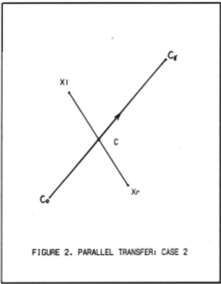
In this case, two arms are not distinguished as the master arm and the slave arm. They work in the same status. In this method it is necessary to compute the positions of both hands and computation of each joint torque while the arms are in motion, so it takes more to execute compared with CASE 1, but it is significant because it can be used with rotational transfer described in the next section. The method of CASE 1 does not seem to be usable with the rotational transfer simultaneously.
For both arms, in addition to gravity loading G(k) and friction F, torque control is applied to generate the following force Ft at each hand.
where Fe is the force. required to
Fe = ka d 2 /dt 2 (C) + kc ( C-(XI+Xr)/2 ) + kd d/dt ( C-(XI+Xr)/2 )
Fe: fixing force vector to some point
C : some point position vector
ka,kc.kd: constant coefficients
Fi · Fs
Fi: interactive force vector
Fe: the external force applied to the hand measured by the force sensor
The force Fe is calculated such that the midpoint between the two hands follow the point C. The force Fl cancels the interactive force expected in the motion. This torque control is applied to the upper 3 joints. For the lower 3 joints, position control is used in order to maintain the hand orientation. If C is moved in some direction, parallel transfer can be accomplished.
The trajectory of C should be planned. For straight line motion, one way of planning the trajectory of C is to Interpolate between endpoints with a sinusoidal function of time, as follows.
C 0 : initial position
C : final position I
t : normalized time The merit of this trajectory is the smooth acceleration and deceleration since the acceleration curve is sinusoidal.
ROTATIONAL TRANSFER
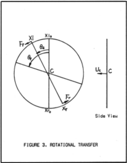
Rotational transfer means that two hands rotate the object around an arbitrary axis. One example of this task is the rotation of a large box or a long bar. If position control is applied to execute this task, the motion becomes awkward. But by using torque control for each joint to generate a force vecter to the direction of the rotation in both hands, the motion becomes very smooth. In this case the distinction of the master arm and the slave arm is unreasonable, so the control of both arms in the same status is more natural.
For each arm, in addition to gravity loading G(k) and friction F, the total force Ft is calculated from the following forces, Fr, the force to generate the rotation of the object around an axis, Fe, the force to fix the center of the object to the rotational center point, and Fi, the force to reduce the interactive force between two hands while In motion. This torque control Is used for the upper 3 joints which decide the hand position. For the lower 3 joints, orientation control is applied according to the rotation.
Fr = f (Ucx(XI-Xr))/IUcx(XI-Xr)l
Fr:
rotational force vector
f : amplitude of the force
Uc: unit rotational vector
XI: left hand position vector
Xr: right hand position vector
Fe .. kc ( C-(XI+Xr)/2) + kd d/dt( C-(XI+Xr)/2)
Fe: force vector required to fix to the center of the rotation
kc,kd:constant coefficients
C : rotational center position vector ( · (XI 0 +Xr 0 )/2)
XI 0 ,Xr 0 : initial hand position
Fi .. Fs
Fi: interactive force vector
Fe: the external force applied to the hand, measured by the force eeneor
where f should be varied in order to transfer the object smoothly and stop at the desired angle position. One way of evaluating f is as follows.
where kcx,ktl,kb: coefficients 8 : planned rotation angle c
8 : actual rotation angle ·
XI 0 ,Xr 0 :
XI,Xr:
81:
initial hand position
actual hand position
final rotation angle
The input data necessary to the rotational transfer are the rotational center position C, the unit rotation vecter Uc which has the direction of the rotation, and the desired rotational angle 8 1 around the vecter Uc. C Is assumed to be at the midpoint between the two hands here, but an arbitrary point may be used.
THE HAND ORIENT A TION
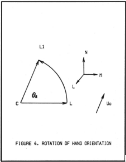
While rotating the object, the hand orientation has to be changed relative to the object. The hand orientation rotates around the unit rotation vector Uc. The hand orientation is represented by orthogonal unit vesters L, M and N. After the rotation of 8 these vecters become Ll, · Ml and Nl.
The angle between Uc and L does not change while In motion. Therefore
The rotational angle of L around Uc is 8 , ILl-ILl I, and · IUclcl. Therefore
( Ucxl )x( Ucxll ) · I Ucxl 1 2 sin8 Uc (3) ·
where
From the above equations, we have
a=cylz-czly
b=czlx-cxlz
c=cxly-cylx
d=cxlx+cyly+czlz
Therefore
Dn is the matrix for which the nth column of D is replaced by the terms on the right hand side in (4). We can obtain M1 and Nl by the same way for M = [mx,my,mz] and N = [nx,ny,nz].
By using the above equation, we calculate the hand orientation R(O ) relating to the object rotational angle. I
CONCLUSIONS
The execut ion of the coordination of two arms requires computations to be executed in runtime such as the exchange of the information between both arms and the computation of interact ive force. These are unnecessary in the control of one arm. Nevertheless, it makes possible performing new classes of manipulation tasks.
The system is effective and reasonable, since it controls the force directly instead of controlling the position which is the indirect variable in the case of controlling forces.
As the fundamental motions of the coordination of two arms, parallel transfer and rotational transfer of an object are considered. By varying the rotational center position C and the rotational vector Uc, more general rotational transfer can be performed. When parallel transfer is added to this general rotational transfer, most motions by two arms seem to be described.
In actual assembly tasks, additional forces from the outside might be appl ied to the object handled by the arms. Since arms must continue the assembly task considering these forces, more sophisticated force control would be necessary and somet imes even the part ial use of position control and visual feedback could be effective.
BIBLIOGRAPHY
- [ 1] R.Finkel, R.Taylor, R.Bolles, R.Paul, J.Feldman, "AL, A Programming System for Automation, " Stanford A.I.Project, Memo No.243, Nov.1974.
- R.C.Bolles, R.Paul, "The Use of Sensory Feedback in a Programmable Assembly System, " Stanford A.I.Project, Memo No.220, Oct.1973.
- R.P.Paul, "Modelling, Trajectory Caliculation and Servoing of a Computer Controlled Arm, " Stanford A.I.Project, Memo No.177, Mar.1973.
- [ 4] T.O.Binford, D.D.Grossman, et al, "Exploratory study of Computer Integrated Assembly Systems, " Progress Report 3, Stanford A.I.Project, Memo No.285, Aug.1976.
- (5] M.D.Roderick, "Discrete Control of a Robot Arm," Stanford A.I.Project, Memo No.287, Aug.1976. ·
- H.lnoue, "Force Feedback in Precise Assembly Tasks," Massachusetts Institute of Technology A.I.Memo No.308, Aug.1974.
- J.L.Nevins, D.E.Whitney, S.N.Simunovic, "System Architecture for Assembly Machines, " The Charles Stark Draper Lab., Memo No.R-764, Nov.1973.
- (8] C.A.Rosen, et al, "Exploratory Research in Advanced Automation," Stanford Research Institute Report, Jan.1976.
- A.K.Bejczy, "Robot Arm Dynamics and Control," California Institute of Technology, J.P.L.Memo TM33- 669, Feb.l974.
- [1 0] E.Nakano, T.lshida, et al, "Cooperational Control of a Pair of Anthromorphous Manipulators "MELARM", " Proc.4th lntern.Symp.lndustrial Robots, Nov.1974 . .
@inproceedings{ijcai1977p173,
  title     = {Force Control in Coordination of Two Arms},
  author    = {Ishida, Tatsuzo},
  booktitle = {Proceedings of the Fifth International Joint Conference on
               Artificial Intelligence, {IJCAI-77}},
  publisher = {International Joint Conferences on Artificial Intelligence},
  editor    = {Raj Reddy},
  pages     = {717--721},
  year      = {1977},
  note      = {Robotics},
  url       = {https://ijcai.org/proceedings/1977/173},
}
TY - CPAPER TI - Force Control in Coordination of Two Arms AU - Ishida, Tatsuzo T2 - Proceedings of the Fifth International Joint Conference on Artificial Intelligence, IJCAI-77 PB - International Joint Conferences on Artificial Intelligence PY - 1977 SP - 717 EP - 721 UR - https://ijcai.org/proceedings/1977/173 ER -Copied
Machine-readable versions of this paper, for tools and AI agents:





