
Recognition Of An Object in A Stack Of Industrial Parts
Proceedings of the Fourth International Joint Conference on Artificial Intelligence. Robots And Productivity Technology. Pages 811-817.
© 1975 International Joint Conferences on Artificial Intelligence
Abstract
This paper describes a method for analyzing an input scene of a stack of industrial parts in order to recognize an object which is not obscured by others. Detecting a simple familiar pattern such as an ellipse in a set of strong feature points, an analyzer selects models of the machine parts from the attributes of other featu .re points around the pattern under the constraints of the proposed models. Finally one of the models is verified through processes of matching the detailed structures of the models to the less obvious feature points.
- A. Guzman, Decompostion of a visual scene s into three-dimensional bodies, Proc. of AFIPS, 33 Part.l, pp291-304, (1968). -
- D. A. Huffman, Impossible objects as nons e nse sentences, Machine Intelligence, 6 pp295-323, (1971).
- M. B. Clowes, On seeing thing, Artifi- ci a l Intelligence, 2 pp79-116, (1971).
- D. L. Waltz, Generating semantic de- scriptions from drawings of scenes with shadows, MIT AI TR-271, (1972).
- G. Falk, Interpretation of imperfect line data as a three dimensional scene, Artificial Intelligence, 3 pplOl-144, (1972).
- R. T. Chien andY. H. Chang, Recogni- tion of curved objects and objects assem- blies, Proc. of 2nd International Joint Conference of Pattern Recognition, pp496- 510, (1974).
- M. Kelly, visual identification of people by computer, AI Project MEMO No.291
- T. Sakai, M. Nagao and T. Kaneda, Com- puter analysis and classification of pho- tograph of human faces, Proc. of 1st USA- JAPAN Computer Conference, (1972).
- G. J. Agin and T. Binford, Computer description of curved objects, Proc. of 3rd International Joint Conference of Artificial Intelligence, pp629-641, (1973) IJCAI
- I. Shirai, A context sensitive line finder for recognition of polyhedra, Artificial Intelligence, 4 pp95-120, (1973). Feature Points Selected Points for TF+ Selected Points for TF Fig.4 Feature points and Selection of Them for Clustering.
References were extracted automatically from the PDF and may contain errors.
Full text extracted automatically from the PDF; figures, tables and equations may differ. The PDF is the version of record.
ABSTRACT
This paper describes a method for ana lyzing an input scene of a stack of indus trial parts in order to recognize an ob ject which is not obscured by others. Detecting a simple familiar pattern such as an ellipse in a set of strong feature points, an analyzer selects models of the machine parts from the attributes of other featu.re points around the pattern under the constraints of the proposed models. Finally one of the models is verified through processes of matching the detailed structures of the models to the less obvi ous feature points.
INTRODUCTION
Analysis of a scene of a stack of ob jects is one of the most important and difficult problems in the studies on the machine vision. Since Guzman found suc cessful heuristics for decomposing scenes into objectsl, many excellent papers have been published on developing better seg mentation procedures.2 3 4 Most of them, however, dealt with perfect line drawings of blocks, and a beautiful extension by Falk was necessary for applying Guzman's idea to input pictures of rather complex blocks worlds where the usual line finders would be likely to make serious errors 5 ·
This paper describes an attempt of augmenting the automatic scene analyzer to handle not only the blocks world but also complicated-shaped objects such as industrial parts. The final goal of our research is to develop procedures for seg menting scenes into objects and deducing names and locations of partly hidden ob jects, but we began the research aiming at a much simpler subgoal: classify and lo cate an object which is not hidden by others. Since shapes of industrial parts are much more complex than those of blocks and the light intensity distribution on their sufaces are not uniform but have significant noise, the usual preprocessors fail to get a reliable line drawing of a stack of the industrial parts. Because of the difficulties in finding correct labels for vertices in the noisy line drawing, neither the recently proposed method for segmenting the scene into curv ed objects 6 , nor its modification along Falk's approach seem to be promising for
This work was supported in part by Grand In-Aid for Scientific Research from the Ministry of Education, Japanese Govern ment. (Grant No.911305, Specific Category,
1974)
Saburo Tsuji and Akira Nakamura Department of Control Engineering Osaka University Toyonaka, Osaka, Japan
our purpose.
We propose an alternative approach along an extension of top down picture processing which could locate less obvi ous parts of the objects utilizing both a priori knowledge and information about more obvious parts. 7 8 Our analyzer de tects a simple familiar pattern in the strong feature points, and selects promis ing models from attributes of the feature points around the pattern under constraint of the proposed models. Then one of the models is verified through processes of matching selected sets of weaker feature points of the object to correspondingparts of the models. The emphasis of the re search is laid on the processes of hypoth esizing and verification of the models which must overcome the difficulties in reasoning about variable perspective views of complex three dimensional bodies.
INFERRING MODELS OF OBJECTS
Input Scene
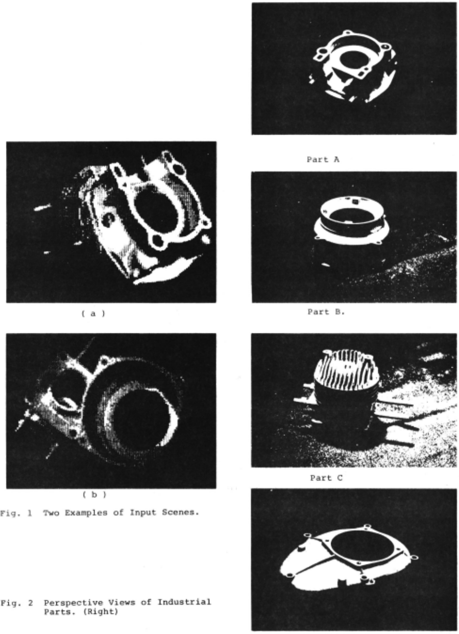
This paper describes a method for ana lyzing an input scene of a stack of parts of small internal combustion engines. Fig.l shows two examples of 128 by 128 digitized input scenes: one part leans on the other part in each picture. In order to simplify the analysis, we make the following assumptions on the input pic tures: 1) at least one object in ~he pic ture is not hidden by others, 2) its top (or bottom) face is observable. These assumptions guarantee that there exist enough information in the input scene to classify the object. The meaning of the first assumption is obvious : we can find in the scene any important feature of the object unless the object itself obscures
the feature.
Considering the characteristics of the engine parts, we introduce the second as sumption. Observation of Fig.2, perspec tive views of three examples of the engine parts, gives us the knowledge that top views of the engine parts are rich in fea tures to characterize them, while their side views are in most cases very poor in distinguishable features. Thus the second assumption assures that some of the impor tant features of the parts are detectable.
However, it must be noted that the two assumptions do not guarantee by any means that the usual line finders or curve fit ters give a reliable line drawing of these e ngine parts, because the shapes of the parts are complicated. Thus the top down type processing is necessary to decide these features as well as their relation ships.
Simple Familiar Pattern as Clues for In terpretation
We already know that enough informa tion of the objects exists in the input picture, however it is not easy to deduce which features belongs to the object in question. Since the usual preprocessor fails to obtain a perfect line drawing of the input picture, the segmentation and recognition processes must use input data and knowledge of the world to suggest and test hypothses on the classes of the ob jects as well as their relationships. Falk applied the above idea to the blocks world where strong constraints exists on the types of vertices. Finding clues for segmentation such as Y, L, or ARROW joints in the imperfect line drawings, his ana lyzer determines kernels of bodies, then one of the prototypes of blocks is hypoth esized for each kernel. Unfortunately, we cannot determines correct labels of vertices in our complicated noisy line drawings, and some clues must be found instead of Y, Lor ARROW joints.
When a human being sees a complicated scene, he unconsciously searches for some simple familiar patterns as cues for in terpretation of the scene. Also his vi sion system transforms the observed pat terns into simpler original shapes utiliz ing range information and knowledge of the world. For example, an ellipse and a tra pezoid in a three dimensional scene, are perceived as a tilted circle and a tilted rectangle, respectively. Our vision sys tem adopts similar mechanism. Finding feature points of the object by simple preprocessing, the analyzer searches a set of the strong feature points for a simple familiar pattern such as an ellipse or diamond shape. If an ellipse is found, it suggests a powerful hypothesis that its original pattern would be a circle. Then coefficients of a linear transformation of it into a circle is determined. They give us valuable information such as the angle of inclination of the key plane on which the key pattern, the simple familiar pattern exists. The analyzer applies the transformation to other feature points, and converts their patterns into original shapes if they are on planes parallel to the key plane.
Now hypotheses of a few promising mod els for the objects are possible from these transformed patterns: we can compare the attributes of the patterns with those of prototypes of the engine parts, and easily exclude ones whose structures seri ously contradict with those of patterns which likely belong to the object. Final ly the techniques of top down picture pro cessing are apllied to the verification process of the models. Different sets of weaker feature points in the scene are sequentially selected and tested whether they coincide with those of the proposed models, until one candidate is selected.
Models of the Objects
Since our vision system repeatedly uses the models of the engine parts, we must carefully design their data structure Agin and Binford proposed an excellent scene analyzer which utilized depth infor mation to sampled points on the objects, and automatically represented complex curved objects by generalized cylinders. 9 Some of their ideas are useful for our purpose, however our system deals with monocular inputs and any attempt of auto matic generation of the models has not been studied in this research. At pres ent, we manually measure the geometrical parameters of the parts, and give a com puter the structures and parameters of the models.
Since all objects are parts of rotat ing machines, it seems convenient to de scribe them in a cylindrical cordinate system whose z axis is a perpendicular to the upper surface through the center of the big hole in it. We can approximate the major portions of the part by pieces of cylindrical sufaces and horizontal planes. As mentioned before, the sides of the engine parts are poor in distinguish able features, and we pay attention to description of the horizontal planes.
Thus our model of an engine part is a set of horizontal sufaces. Each plane is characterized by its height from the base, an outer boundary, inner boundaries and an index of observable direction (top or bottom) · Both the outer boundary and the inner boundary of the big hole are de scribed by arcs or line segments, and the inner boundaries of small holes are characterized by their areas and the posi tions of their centers. Another distin guishable feature, the horizontal rods of part A ~nd part C in Fig.2, is described by their heights and positions of both end points. These features are arranged in a table which is stored in a disk memory. Other features such as colors or textures of the surfaces have not been implemented yet.
SYSTEM DESCRIPTION
Flow of Processing
Fig.3, an overall diagram of the scene analyzer, displays the flow of processing as well as the experimental results of separate modules in it to the input scene of Fig.l (b).
Two different modules EDGE FINDER and HOLE FINDER are designed for preprocessing 128 by 128 digitized input pictures.
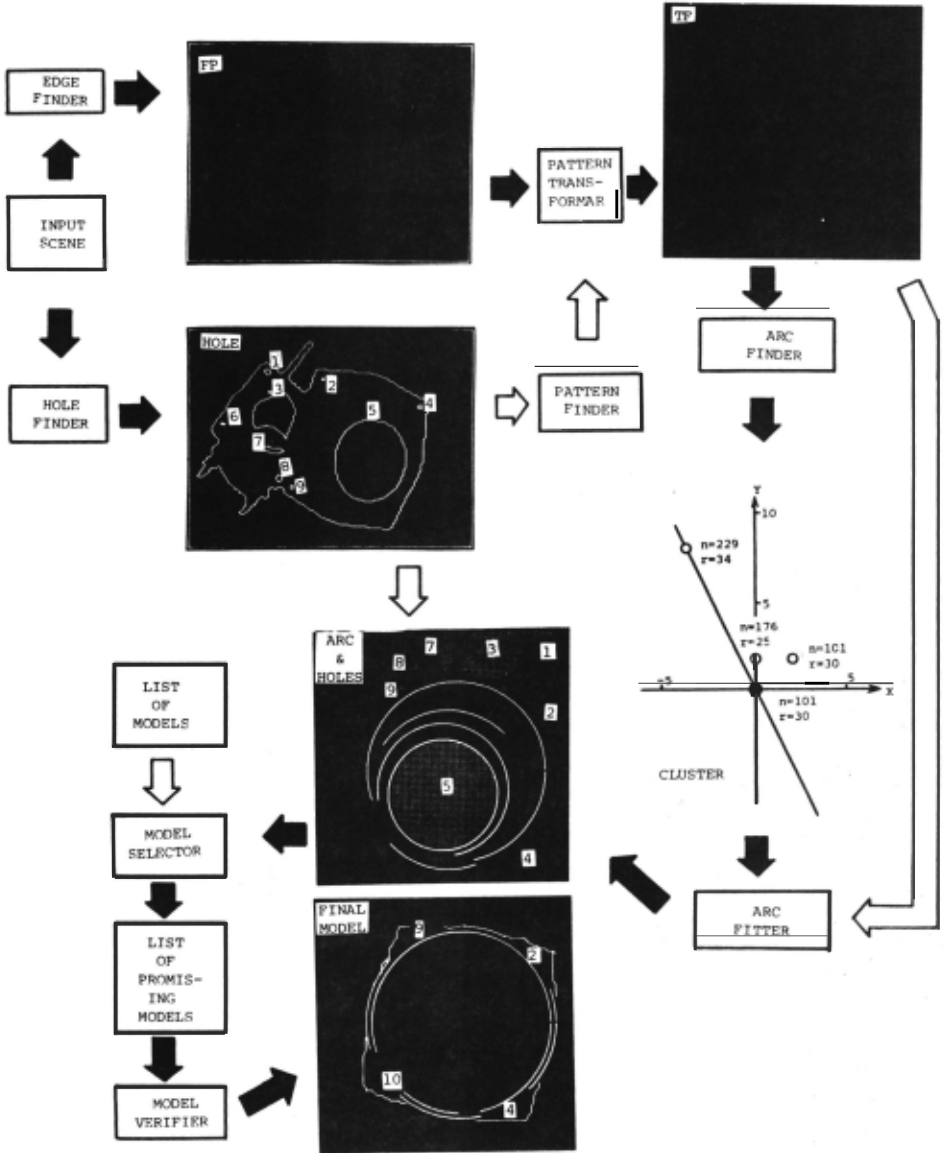
EDGE FINDER uses a simple gradient ~P~=~ tor to find edge points which are memori zed in an array FP (FEATURE POINT). The other module HOLE FINDER is a specialist to search for obvious holes. PATTERN FINDER is for finding the simple familiar pattern, however only a procedure for de tecting an ellipse of considerable size in the set of the obvious holes.
In order to find circular edges of the object, some qualified points in FP are mapped on TF (TRANSFORMED FEATURE) by a linear transformation whose coefficients are evaluated from rough parameters of the ellipse. ARC FINDER first searches for arcs in TF by a clustering method, then evaluate attributes of the reliable arcs, which are compared with those of moae~s by MODEL SELECTOR. Finally MODEL VERIFI ER matches detailed structures of models recommended by MODEL SELECTOR to the cor responding parts of the object, and choos es the most promising one.
The system is programmed in FORTRAN and SABR (an assembler language), and the typical computing time on a mini-computer PDP8/E (12kw of core memory, 28kbytes of buffer memory, and 1.8Mw disk memory) is about 15 minutes.
Preprocessing
We have not paid much attention to de sign a good preprocessor in this research. EDGE FINDER applies a local gradient oper ator and thresholding at every point in the picture, and stores its absolute val ue and angle in FP.
Since the background of the stack is dark, HOLE FINDER easily find the outer boundary of the stack. Then an adaptive threholding technique is applied to the region surrounded by t~e outer boundary, and several dark domains are obtained. Testing whether each boundary point of the domain or one of its neighbours has a sig nificant gradient, HOLE FINDER excludes some dark domains which are considered as shades. Some small holes, however, ~~~ misclassified as shades because of lack of sharp light intensity change on its boun dary, such as a small hole at the lower right corner of the object in Fig.l (b) (see HOLE in Fig.3).
Transforrnation into Original Shapes
An affine transformation of the el lipse found by HOLE FINDER and PATTERN FINDER into its auxiliary circle, is use ful to simplify the hypothesizing and veri fication process. The distance from the input TV camera to the objects is much larger than the sizes of the objects, therefore our vision system has little parallax, and the transforamtion rules be come very simple:
- {1) pattern on parallel planes tc t~~ ~~ !ipse are transformed into their original shapes,
- {2) the rotating axis of the object (z axis of the model) coincides with the mi nor axis of the ellipse,
- a parallel line to the rotating axis is ma7ped on its extension whose length is g./ a2-b2)/b, where a: length of thema jor axis, b: length of the minor axis, g.; actual length of the line.
Clustering Method for Detecting Arc
We use a clustering method, an exten sion of Duda and Hart's method,to search for reliable arcs in a set TF of the transformed feature points. In order to facilitate the detection, the analyzer first selects promising feature points to be elements of arcs, then classifies them into two groups TF! and TF_. If a fea ture point is an e ement of an arc, it must have a gradient whose radial compo nent g has a significant value. There fore ar feature point whose lg I is larg er than a thresholding value r is trans formed into TF+ or TF_ depending on the sign of g . This classification is effectiverfor preventing confusion be tween two adjacent arcs. Since the pur pose of arc finding is for detecting the circlular edges of the object, feature points which exist on the boundaries of detected small holes are excluded from TF. Fig.4 illustrates the feature points in Fig.l (a) and points selected from them for TF+ and TF_.
Duda and Hart suggested that their me thod is applicable to find circles in the scene. 1 O If one wishes to adopt their me thod for detecting circles, searching for clusters in a three dimensional space on which every feature point is mapped, is necessary. Fortunately, we have the know ledge that centers of all arcs are on the rotating axis, therefore we look for clus ters in a simpler two dimensional space.
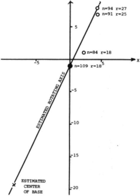
Consider orthogonal cordinates (x,z) on the transformed plane, where x and y axes coincide with the major and minor axes of the ellipse E. The first stage of clustering is to test a hypothesis that there exist an arc A(r,O,z) on the plane, where r is the radius of the arc and (O,z) are the cordinates of its center. N(r,O,z), number of feature points in TF+ (or TF ) which satisfy the hypothesis, is mapped on PLUS rz (or MINUS rz) plane. If a sharp peak should exist on this plane, it would indicate verification of the hypothesis. The experimental results, however, do not have a sharp peak but me dium mountain ridges in most cases, be cause the estimation of the parameters of E is rough.
Since the estimation of a,b is more accurate than that of the orientation of the pricipal axis of E, the s~c0~~ &t~;~
e center of key circle,
o center of other arc,
n:number of feature points on arc, r:radius of arc.
of cluster finding is to correct theerror of the orientation by a hill climbing me thod. Deciding the highest point (r,z ) in the mountain ridges, the analyzer 0 sets the starting center point at (O,z 0 ). Then it iteratively searches the neigh bourhood of n-th center point (x ,z ) for a better center point (x +l'z n) n such that M~x[N(r,xn+l'zn+l)]n M~~1~(r,xn,zn]'
until the center point comes to ~ stand still at the highest peak. When the peak is found, the feature points belonging to the best arc are excluded from TF+ (or TF ) and the hill climbing process is re peated. Fig.5 shows an experimental re sult of the above mentioned procedures whose input is a set of feature points illustrated in Fig.4. The correct direc tion of the rotating axis is estimated by the majorities of the clusters. Some times a few clusters are located far from the corrected axis, because the arcs are not real edges of the object but borders of the shadows projected on the object.
Next the arc fitting process is per formed which decides reliable portions of arcs. Kernels of circular St::.;,;:;,.::ui..o vf considerable length are determinea i~rs~ on which the feature points desely exist, then the kernels are extended to feature points which are located at the neigh bour hoods of their end points. Fig.6 shows the results of the arc fitting pro cess whose inputs are transformed feature points in two pictures of Fig.l.
Selection of Models
MODEL SELECTOR utilizes attributes of arcs and small holes on the transformed plane to choose and rank a few promising models in the list of prototypes of the engine parts. ·
Since the v~s~on system uses the mono cular TV camera, we can evaluate only the relative sizes of the objects. Thus the system normalizes measured geometrical parameters by the radius of the key circle C, which is transformed from the ellipse E. The detected arcs have the following valuable information:
(1) the normalized radius and length of the circular edge of. the object, (2) the normalized height from the plane including C,
(3) the arc belongs to the object in ques tion if its center is on the rotating axis and the relative height has a reasonable value.
MODEL SELECTOR checks whether these attributes of the arcs are acceptable to each prototype. Table 1 shows a part of arcs in the list of prototypes. Observ ing Table 1, we know that there areplural candidates for the key hole C in a single view of one engine part (Part B bottom view has two candidates). Thus MODEL SE LECTOR repeatedly tests the hypothesis that each candidate in every prototype is really the key circle, by comparing nor malized radii, heights and angles of de tected arcs with those of prototype, and easily exclude many prototypes from the list of promising prototypes.
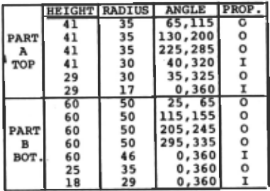
Two examples of sets of arcs illus trated in Fig.6, have common promising prototypes, bottom view of Part B and top view of Part A, because the selection must be conservative to allow for the errors of the arc finding and fitting process.
Now MODEL SELECTOR uses the informa tion of the small holes to compute scores of matching of the object to the selected prototypes. If an arc belongs to the ob ject, then a fan-shaped area which is de temined by the circular segment and its center, is considered as a portion of the object. When a small hole is located in the fan-shaped areas or their neighbour hoods, the analyzer examines whether each promising prototype has the corresponding hole or not. And a prototype whosestruc ture satisfies all qualified small holes as members of the object, is considered as the most promising one. Fig. 7 shows all detected holes in Fig.l (a) by HOLE FINDER. Six of seven holes in the top view of Part A is found, and five small holes are qualified as the members of the prototype if the selection is correct, while a wrong selection of the bottom view of Part B satisfies three smallholes at most, because of the size condition of the holes.
Verification of Selected Model
The final stage of the analysis is for MODEL VERIFIER to verify one of the pro posed models by MODEL SELECTOR. We use a model guided processing for evaluating matching of the object to the most pro mising prototype which suggests a feature to examine next as well as its location. At present, the method is applied to exa mine the features on the top face of the · object .
The angle of rotation of the object is hypothesized from the structure of top face of the model, the position of the rotating axis on the top face of the ob ject, and detected attributes such as position of small holes and arcs. If a small hole in the model's top face has not been detected, HOLE FINDER re-exam ines the corresponding area utilizing a lower threshold value for testing the gradients than that used for the initial hole detection. (Fig.3 FINAL MODEL shows no.lO small hole is detected by this re examination.)
Arcs of the top face are also re-exa mined at estimated areas from parameters of the model's arcs and those of relia bly detecte d arcs in the object. Similar procedures are applied to find linear edges of the object. A set of transform ed feature points whose absolute values of their gradient are larger than 1/2 of the threshold used in the first arc find ing, is used for these re-examination process to test weaker feature points. FINAL MODEL of Fig.3 shows most parts of the top face are detected, however some portions of circular or linear edges are not detected because of little change in brightness at these portions.
DISCUSSION
A method is proposed for recognizing complex-shaped engine parts which are not obscured by others. The results are sat isfactory for the illustrated examples, however the system has several difficulti es which must overcome in near future.
We use only the ellipse as the simple familiar shape, which is impotant clue of processing. Simple figures such as a par allelogram or a diamond shape, must be used as the cues. We can find the paral lelogram by Hough transformation, however a difficulty exists that there are infi nite rectangles as the original shapes of the parallelogram. Therefore the system must search the list of prototypes for a rectangle, and calculate the coefficients of the affine transformation which con verts the parallelogram into the rectan gle, and computing time would increase considerably.
We assume the existence of a perfect or near perfect ellipse in the input pic ture, however sometimes a part of the ellipse is hidden by some part of the ob ject. Thus we have to modify PATTERN FINDER to evaluate more accurate para meters in most cases .
At present, our system does not use information of a side view of the object, which is useful for the parts whose top faces have small flat portions. The sys tem does not use color or texture infor mation either, however we can easily implement them in the analyzer. There is a technical limitation of size measure ment by monocular vision input, and the range finder would augment our system con siderably.9
Finaily context-sensitive processing 11 must be used at the verification process where some portions of edges of the pro posed model are not detectable by the simple changing threshold value.
@inproceedings{ijcai1975p129,
  title     = {Recognition Of An Object in A Stack Of Industrial Parts},
  author    = {Tsuji, Saburo and Nakamura, Akira},
  booktitle = {Proceedings of the Fourth International Joint Conference on
               Artificial Intelligence, {IJCAI-75}},
  publisher = {International Joint Conferences on Artificial Intelligence},
  editor    = {Patrick Winston and Carl Hewitt},
  pages     = {811--817},
  year      = {1975},
  note      = {Robots And Productivity Technology},
  url       = {https://ijcai.org/proceedings/1975/129},
}
TY - CPAPER TI - Recognition Of An Object in A Stack Of Industrial Parts AU - Tsuji, Saburo AU - Nakamura, Akira T2 - Proceedings of the Fourth International Joint Conference on Artificial Intelligence, IJCAI-75 PB - International Joint Conferences on Artificial Intelligence PY - 1975 SP - 811 EP - 817 UR - https://ijcai.org/proceedings/1975/129 ER -Copied
Machine-readable versions of this paper, for tools and AI agents:
 Welcome
 Future Conferences
 AI Journal Division
 IJCAI Proceedings
 About IJCAI
 IJCAI Awards