
Scene Segmentation By Velocity Measurements Obtained With A Cross-Shaped Template
Proceedings of the Fourth International Joint Conference on Artificial Intelligence. Robots And Productivity Technology. Pages 803-809.
© 1975 International Joint Conferences on Artificial Intelligence
Abstract
This paper presents a method of segmenting a scene into its basic objects on the basis of motion The velocities of points are approximated by associating them to sets of reference edges in the scene. These measurements are then used to group the points. A basic tenant of this work is that all points of a single object have the same velocity values. Accordingly, points with the same velocity measurements are grouped together. Since the motion of an object . is independent of its other visual characteristics, whole objects (not surfaces or edges) are initially included in one segment. The program successfully grouped points from internally generated scenes with 100% accuracy, Points from real test scenes were grouped correctly 90% of the time on the average, The poorest result was 42% accuracy, The best was 100%.
- 'Bibliography Brice, C, R, and c. L, Fennema, "Scene Analys~s Using Regions," Arti- ficial Intelligence, 1• 1970, 205.
- Endlich, R. M,, D, E. Wolf, D. J, Hall, and A, E. Brain, "Use of a Pat- tern Recognition Technique for Determining Cloud Motions from Sequences of Satellite Photo- graphs," Journal of Applied Meteorology, 10, 1971, 103-117.
- Guzman, A,, "Oecomposi tion of a Vi- sual Scene into Three Dimensional Bodies," AFIPS Proceedings, Fall Joint Comp~Conference, ]1-,--- ~ 291-304, .
- Leese, J, A,, c. s. Novak and V, R, Taylor, "The Determination of Cloud Pattern Motions from Geo- synchronous Satellite Image Data," Pattern Recognition, 2, 1970
- Potter, J., "Motion as a Cue to Seg- mentation," IEEE Transactions S!~C, sr.~c-_2, r, ~ay, 1975. 390-394.
- - Smith, E. A, and D. R. Phillips, "Au- tomated Cloud Tracking Using Pre- cisely Aligned Digital ATS Pic- tures," IEEE Transactions on Computers, ~. 1972, 715-72~
- Uhr, L, and C. Vossler, "A Pattern Recognition Program that Gener- ates, Evaluates and Adjusts Its Own Operators," L. Uhr (ed.), Pattern Recognition, John Wiley and Sons, New York, 1966, 349- 364,
References were extracted automatically from the PDF and may contain errors.
Full text extracted automatically from the PDF; figures, tables and equations may differ. The PDF is the version of record.
Introduction
One of the most important steps in processing digitized scenes is the segmen tation of the scene into its basic objects ("Basic objects" in the sense used here correspond roughly to the common nouns that refer to three dimensional objects which would normally be used in the description of a scene), Guzman [1968] segmented line drawings into objects on the basis of ver tex configurations, Brice and Fennema [1970] segmented scenes directly into sur faces on the basis of the gray scale values of the picture elements. It is the au thor's belief that the .motion of objects in a scene can be profitably used for segmen ting a scene into its component objects. Potter [1975] proved the feasibility of such an approach, The process envisioned here is not intended to solve the problem of segmentation by itself, but instead pro vide a powerful method of dividing a scene into a set of fundamental divisions which correspond to the scene's basic objects. A basic consideration in the design of the system was that it should be compatible with other segmentation schemes. The au thor hopes to integrate this system with other systems so as to achieve more com Plete and accurate scene segmentation.
The use of motion for scene segmenta tion results in two subproblemss first, how to extract motion information; second, how to use motion information for segmem
tation ~his paper discusses a method of
*The research reported in this paper was completed by the author while a stunPn+ ~t
the University of Wisconsin -Madison, the pictures were taken only a few moments apart, the edges* could be correlated be tween the pictures by their spatial posi tion alone, A motion measurement was ob tained by determining the displacement of the edges between pictures from a given point on a superimposed absolute reference grid, These same general assumptions and approaches are taken here, however instead of determining the x- and y-motion com ~onents seperately as was done in Potter L1975], a "cross-shaped template" is used to determine the actual velocity in one step,
The "Cross-shaped Template"
The basic concept of velocity extrac tion to be used here is to find a feature in one picture, find the corresponding feature in a second picture and use the observed displacement as a measure of mo tion, The major problem with feature matching is that a feature has to be . ini tially found ( and identified), One way of circumventing this problem is to extract templates from one picture and in this man ner, generate features, This approach was fir~t discussed by Uhr and Vossler [1966], The1r templates were rectangular and of a fixed size, If such a template happens to be defined in an area of the picture that contains little information, then there is little significance in its matching or failing to match in a subsequent picture,
The "cross-shaped" template (here after referred to as simply the cross tem plate) contains two advantages for motion extraction purposes over the Uhr and Vossler template generation scheme, First, the template is cross-shaped as opposed to rectangular. This results in a consider able reduction of points that need to be processed for matching, In figure 1, for example, a five-by-seven rectangular tern-
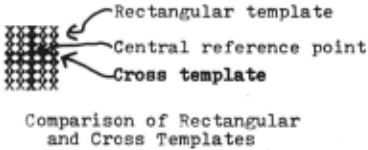
*More accurately, discontinuities in gray scale values were used instead of edges. However, since "edge" is a more easily understood term, it will be used in this paner, It should be kent in mind how ever, that wherever "edge" is used, dis continuity in eray scale value should be used, See Potter [1975l for a more com plete discussion plate contains 35 points. But the five by-seven cross template contains only 11 points. Second, the cross template is of variable size, The length of an arm of the cross is determined by the distance from the central reference point (or sim ply center of the template) - to the nearest edge, The variable size of the template greatly increases the likelihood that it contains useful information, The cross template is defined by taking the point at the intersection of the arms as the center point of the template and the distance from the center to the closest edge in four given directions as the length of the corresponding arms, That is, an association of distance and direction forms the basis for the cross template, The association operates on the assumption that every point of a super imposed absolute reference grid is sur rounded by edges in the picture. In any one picture, a reference point of the grid may be surrounded by any number of edges. A unique association is established be tween a reference point and an edge by picking a direction and recording the dis tance from the point to the nearest edge, In figure 2, the point (x,y) is surrounded by the edges a, b, c, d, e and f, Ry re stricting the direction of association to the positive x-axis, the number of edges is reduced to three· edges b,c and d, This number is reduced to one (and there fore a unique association) by choosing the closest edge, In figure 2, the point (x,y) and edge b are associated uniquely by the positive x-axis direction and the distance between them, three units The point (x,y) and the edge b are uniquely associated by the positive x-axis direction and the distance of three units.
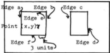
Unique Association of a Reference Point and a Reference Feature Figure 2
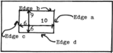
A template must be sufficiently unique that "false matches" do not occur An ef fective design for a unique templ~te con sists of four orthogonal arms. Thus a "cross-shaped" template is defined by a set of four rays parallel to the positive x-, positive y-, negative x-, and negative y axes In figure Ja, the cross template is defined by uniquely associating the point (x,y) with the closest edge (edge a) in the positive x-axis direction by the dis tance value of 10 units, with the closest edge (edge b) in the positive y~axis di rection by the distance value of 9 units, with the closest edge (edge c) in the neg ative x-axis direction by the distance value of 6 units, and with the closest edge (edge d) in the negative y-axis di rection by the distance value of 6 units,
a
b
Cross Temnlate Definition for Various Objects
Figure 3
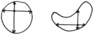
In figure Ja, the cross template is defined by the edges of a rectangular ob ject. Figure Jb illustrates the fact that cross templates can be used with any arbi trarily shaped rigid figure It should be kept in mind that although most of the ex amples in this paper are rectangular and have straight edges, the only requirement for application of the cross template is that the object does not change shape be tween pictures.
Velocity Determination
After the cross template has been de fined in one picture, it is moved around the second picture until an exact match is found, The cross template is sought in a regular manner. Each of the absolute ref erence points in the neighborhood of the reference point used as the center of the defining template is tested as the center point of a matching template. First the points along the positive x-axis are test ed, then the points along the negative x axis, then the points along the positive y-axis and finally along the negative y axis. Each axis is searched until a search length parameter is exceeded, This parameter is set by the user and reflects the maximun number of absolute reference units an object can move between pictures.
The search along the axes is a heuris tic approach to finding a matching tem plate since the actual movement of the ob ject may be oblique to both axes, The searching routine looks for a match of the total length of the perpendicular arms of the template (i.e, total y-arms length, if searching along the x-axis), If a total length match is found, the true y-dis placement can be easily calculated, The search along the perpendicular axis (y axis in this case) is then started from this newly calculated reference point. When (or if) a total x-arm match is found, the x-displacement is calculated, The ab solute reference point obtained by calcu lating the x- and y-displacements, is tested as the center of a matching tem plate, If successful, the x- and y-dis placement values are used as a measurement of the x- and y-axes component velocities. If the template does not match, the search continues Points for which no matching template can be found are assigned a "null" (not to be confused with zero) velocity value.
The velocity value obtain~d from this process is associated with the correspond ing reference point in the last picture taken. The reason for associating the ve locity with the reference point is that if the reference point corresponds to some physical point of the object, then that physical point does have a velocity, More over, at an initial level of processing, there may not be any other entity (edge, corner or feature of any type) that the motion value can be meaningfully associ ated with.
The main advantage of this approach to velocity extraction is that it is object independent, It can be used on any size or shape of object. The only requirement is that a number of spatial discontinui ties in gray scale be associated with the object~ Every visible object meets this requirement, Perhaps more important is the property that this procedure can be applied to any point of a scene without any prior knowledge of the nature of the object which is at that point, Therefore, the information obtained by this procedure is available to be used at all levels of scene processing,
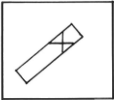
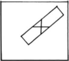
Unfortunately, this velocity extraction procedure does not always detect the cor rect velocity, Under certain circumstances it can not detect motion parallel to an edge, The situation arises when the ex tracted template is not unique, Figure 4a shows an example of such a situation, The condition illustrated in the figure is complicated, Fi~st, the object must have two parallel s~des. Second, the two sides must be long enough and of such an orientation that they constitute the de fining discontinuities for all of the arms An Example of Oblique Motion
a
b
Figure 4
of the template. Third, the motion of the object must be parallel to the two sides. All of these conditions are expressed in the phrase "oblique motion parallel to two edges" or "oblique motion" for short. ·
The problem of oblique motion is more theoretical than practical, Since it a rises from the relationship between the orientation of the arms of the template and the two parallel sides of the object, whenever the situation is detected, a new template can be constructed which avoides the problem. The new template need only to be constructed with one set of arms parallel to the parallel sides. This new ly definded template will extract the cor rect velocity, Unfortunately, this is a somewhat ad hoc solution to the problem,
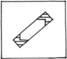
The theoretical problem of oblique motion can be eased slightly by the ob servation that a human can not directly detect motion under similar conditions either. Instead, motion of the parallel sides seems to be inferred from the ob served motion of the ends (or "remainder") of the object. Therefore, a less ad hoc but perhaps more difficult solution is to rely on the knowledge of the real world and deductive capability of a monitor. For example, all of the points in the shad ed areas of the object in figure 4b will have accurate motion measurements, A
"smart" monitor should be able to infer that points with zero motion values which lie between the shaded areas are the result of oblique motion and should be given the same motion values as the bracketing points.
Scene Segmentation
The points of a scene are grouped into segments on the basis of the computed x and y-axis velocity components. The avowed purpose of this procedure is to obtain a crude first approximation of the basic ob ject segments in a scene, Accordingly it is not essential and in fact wasteful to process every absolute reference point. Instead, every n-th point (a system para meter) is processed, The points are proc essed in serial Thus, after the velocity values of a point have been determined, they are compared with the velocity values of previously processed points which have been divided into groups on the basis of their velocity measurements. If an exact match of velocity magnitude and direction of both the x- and y-axis components exists between the point and a group, the point is added to the group, If there is no match, a new group is created with the present point as its first member. This process is repeated until all of the points selected have been processed, In this elementary algorithm, points with "null" velocity values are grouped with points which have zero velocity values (This group corre sponds roughly to the background of a scene).
Results
The velocity extraction and scene seg mentation program(VESS) was implemented in FORTRAN IV on a DATACRAFT computer, The program required 24k memory locations (16 bit words). The pictures were taken by a KGM ll)TM television camera connected via a Zeltex analog-to-digital converter to a PDPll/20 computer, Each 5000 byte picture was transmitted from the PDP11 to the DATACRAFT by an asychronous interface unit.
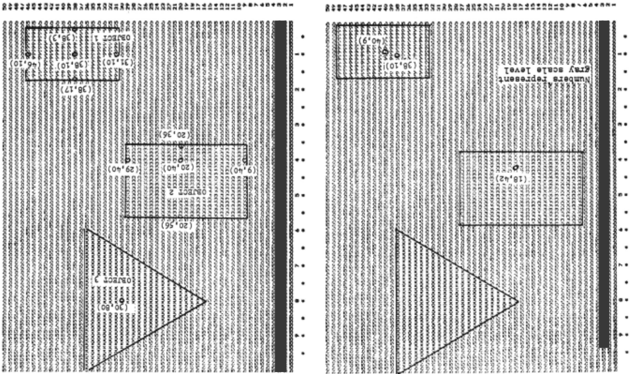
The VESS program was tested on various scenes. It was completely effective on internally generated scenes of rigid, non occluded objects. These scenes contained three or four rectangular and triangular objects with various types of motion. The upper limit of four is due to the conve nience of displaying a scene if the gray scale levels are limited to a single digit, Figure 5 is an example of an internally generated scene of three objects.
Starting from point (5,5) every 10th point was processed. That is, the 50 points- (5,5), (5,15). ... (5,95), (15.5), · . . ( 15 , 9 5) , . . · · . · ( 4 5 , 9 5) - were put into segments on the basis of their motion. Of the fifty points processed for the scene shown in figure 5, all were correctly grouped, Four groups were formed, one for each object and one for the background. Every point in every group was from the same object (background being an "object").
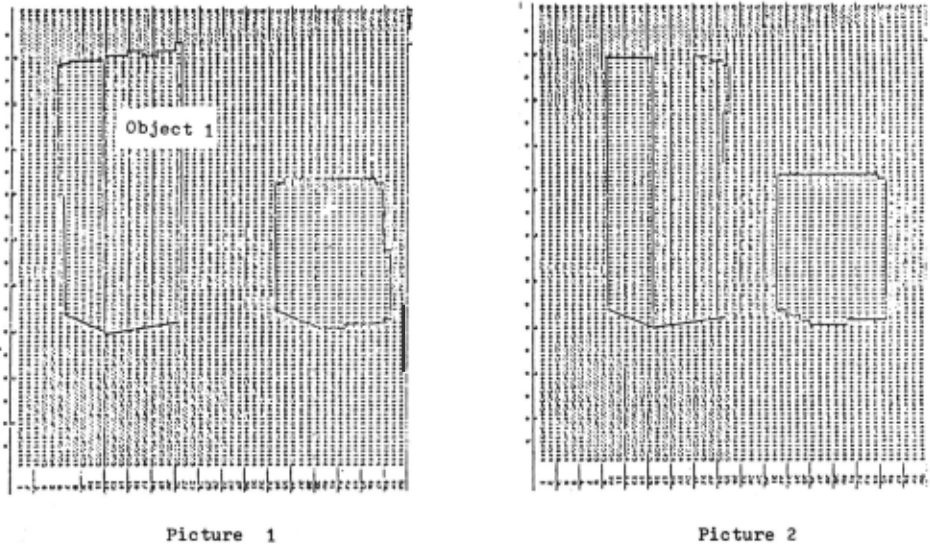
Four different real scenes of one or two rigid, non-occluded objects were used for testing the basic segmentation program. The first scene is shown in fig ure 6 Table 1 shows the results of four runs. Three of the runs used the same 50 point sample used to test the generated scenes. ~wo parameters were used to ac commodate noisy data. They were varied from zero to two. One of the two para meters determined the discrepancy in gray scale value allowed before an edge was '"detected." The other parameter deter mined the tolerance in velocity values allowed in grouping points. As can be seen the best results were obtained when the "deltas" were set to 1.
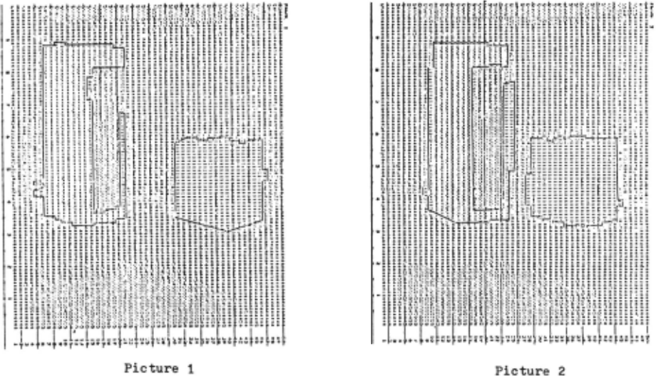
The poor results for object 1 in scene 1 were due to the lack of contrast between the right hand surface (orange) and the background (yellow). A second scene was taken with the right side of ob ject 1 black with an orange insert. A ninety point sample ({2,5), {2,15), ... ( 2 .95). (7 .5). ... (7 .95). .·.... (47 .95)) was used for this test. The change in color resulted in an improvement to 61% correctly classified as shown in the scene 2 column of table 1.
A third test scene was made with the entire right face of object 1 con trasting with the background. The results of this test run were approximately the same as the previous one. APparently the shadowy area between the objects in the second scene caused a decrease in contrast, so a fourth test scene (not shown) was taken of a single multi-colored object. The results were considerably better as shown in the scene 4 column of table 1. The averages of all tests (with "deltas" set to 1) are given in the last column of table 1.
A major problem in these tests with real data was the noi se present in the pictures. The edge noise was such that "large" objects were required. Large ob jects can only be moved slightly before being outside of the field of view of the TV camera. The scenes used constituted a compromise of these aspects and consisted of moderately sized objects (4 to 7 in ches long) in a field of two feet by one and a half feet. These limitations pre vented using scenes with more than two objects.
During these test runs, the segmen tation program processed on the average one point every 5.5 seconds. The fastest processing was one point every 2.4 sec onds on the generated scene data. The real scene data was processed at one point every 6 seconds.
Conslusion
This paper shows that the use of mo tion for scene segmentation can be ap plied to quite general scenes. The cross template can be used to extract the motion of any arbitrarily shaped, rigid, non occluded object. The motion values so ob tained can be effectively used to segment a scene into its moving components and "background~" Although the scenes in this paper were restricted to non-occlud ed objects, the approach presented here seems applicable with slight modifications to scenes with occluded objects. This problem is currently under investigation and results should be forthcomming short lY. The primary drawback of the cross template is its failure to detect "oblique motion." However, on the whole, this process seems to be quite promising as a first step in the segmentation of complex scenes since the groupings are independent of the color (or gray scale value) of the objects in the scene
| Sc ne | |||||||
|---|---|---|---|---|---|---|---|
| 1 (Figure | 6) | 2 | J | 4 | A.ver- ae.e | ||
| Deltas | 0 | 1 | 2 | 1 | 1 | 1 | 1 |
| Correct | O% | 25% | 17~1, | 61% | 67% | 89% | 46% |
| Object 1 No Value | 92 | 25 | 17 | 17 | JJ | 11 | 25 |
| Incorrect | 8 | 50 | 67 | 22 | 0 | 0 | 29 |
| Correct | JJ | 100 | JJ | 89 | 80 | - | 39 |
| Object 2 No Value | 67 | 0 | 67 | 11 | 0 | - | 6 |
| Incorrect | 0 | 0 | 0 | 0 | 20 | - | 6 |
| Correct | 75 | 100 | 100 | 100 | - | - | 100 |
| Back- ground No Value | 25 | 0 | 0 | 0 | - | - | 0 |
| Tnr.orrP~t- | 0 | 0 | 0 | 0 | - | - | 0 |
z e.zn+01d
~ a.znju aueos tWOTdA.L
Acknowledgement
The author wishes to express his grat itude to Dr, L, Uhr, who provided many helpful suggestions and criticisms during the course of this research, This work was supported in part by a grant from the National Science Foundation (GJ-36312),
'Bibliography
- Brice, C, R, and c. L, Fennema, "Scene Analys~s Using Regions," Arti ficial Intelligence, 1· 1970, 205.
- 2 Endlich, R. M,, D, E. Wolf, D. J, Hall, and A, E. Brain, "Use of a Pat tern Recognition Technique for Determining Cloud Motions from Sequences of Satellite Photo graphs," Journal of Applied Meteorology, 10, 1971, 103-117.
- Guzman, A,, "Oecomposi tion of a Vi sual Scene into Three Dimensional Bodies," AFIPS Proceedings, Fall Joint Comp~Conference, ]1-,--- ~ 291-304, .
- 4 Leese, J, A,, c. s. Novak and V, R, Taylor, "The Determination of Cloud Pattern Motions from Geo synchronous Satellite Image Data," Pattern Recognition, 2, 1970
- Potter, J., "Motion as a Cue to Seg mentation," IEEE Transactions S!~C, sr.~c-_2, r,~ay, 1975. 390-394. -
- 6 Smith, E. A, and D. R. Phillips, "Au tomated Cloud Tracking Using Pre cisely Aligned Digital ATS Pic tures," IEEE Transactions on Computers, ~. 1972, 715-72~
- Uhr, L, and C. Vossler, "A Pattern Recognition Program that Gener ates, Evaluates and Adjusts Its Own Operators," L. Uhr (ed.), Pattern Recognition, John Wiley and Sons, New York, 1966, 349364,
@inproceedings{ijcai1975p128,
  title     = {Scene Segmentation By Velocity Measurements Obtained With A Cross-Shaped Template},
  author    = {Potter, J.},
  booktitle = {Proceedings of the Fourth International Joint Conference on
               Artificial Intelligence, {IJCAI-75}},
  publisher = {International Joint Conferences on Artificial Intelligence},
  editor    = {Patrick Winston and Carl Hewitt},
  pages     = {803--809},
  year      = {1975},
  note      = {Robots And Productivity Technology},
  url       = {https://ijcai.org/proceedings/1975/128},
}
TY - CPAPER TI - Scene Segmentation By Velocity Measurements Obtained With A Cross-Shaped Template AU - Potter, J. T2 - Proceedings of the Fourth International Joint Conference on Artificial Intelligence, IJCAI-75 PB - International Joint Conferences on Artificial Intelligence PY - 1975 SP - 803 EP - 809 UR - https://ijcai.org/proceedings/1975/128 ER -Copied
Machine-readable versions of this paper, for tools and AI agents:





