
Recognition of Hand-Printed Numerals Reduced to Graph-Representable Form
Proceedings of the Second International Joint Conference on Artificial Intelligence. Pages 322-331.
© 1971 International Joint Conferences on Artificial Intelligence
Abstract
A method for reducing hand-printed characters to directed graphs is described. When hand-printed characters are reduced to this form, area zoning techniques which have been successfully applied in real time environments can be used. Alternatively, the data in this form can be used to generate descriptions in a simple character-description language.
- Rohland et al, "The design of an O.C.R. system for reading handwritten numerals" A.F.I.P.S., Conf. Proc . , Vol.33, Pt.2, 1968, pp 1151-1162.
- Greanias et al, "The recognition of hand- written numerals by contour analysis" I.B.M. J. of Res. and Dev., Vol. 7, Jan. 1963, pp 14-21.
- Munson, J. H. "Experiments in the recog- nition of handprinted text" A.F.I.P.S., Conf. Proc., Vol.33, Pt.2, 1968, pp 1125- 1149.
- Nagy and Tuong, "Normalization techniques for handprinted numerals" I.B.M. J. of Res. and Dev., Vol.l3, No.8, Aug.l970, pp 475-481.
- Casey, R. G. , "Movement normalization of handprinted characters" I. B. M. J. of Res. and Dev., Vol.13, Sept.l970, pp 548-557.
- Parks, J. R., private communication.
- Bernstein, M. I., "A method for recog- nizing handprinted characters in real time" Pattern Recognition, Academic Press, 1968, pp 109-114.
- Parks, J. R., "A multi-level system of analysia for mixed font and hand block printed character recognition" Automatic Interpretation and Classification of Images, Academic Press, 1969, pp 295-322.
- Shaw, A. C., "Parsing of Graph Representable Pictures" J.A.C.M., Vol.l7, No.3, July 1970, pp 453-481.
References were extracted automatically from the PDF and may contain errors.
Full text extracted automatically from the PDF; figures, tables and equations may differ. The PDF is the version of record.
1. Introduction
With the development of large computers, - the need for an alternative to the manual trans cription of printed data has been partially solved, for a limited number of fonts, by the development of fast O.C.R. machines. A similar need exists for transcribing hand-printed data in situations where machine-printed characters are not, or cannot be used. The only commerc~f~ machine developed at present is the IBM 1287, which reads numerics and 5 control characters and is based on a contour-following technique, described in reference (2).
Global techniques, where a pattern is con sidered as a singl£ entity represented by a number of independent parameters, have been applied successfully to fixed and special O.C.R. fonts. The variations in unconstrained hand printed characters make them entirely unsuitable for these techniques, and efforts have been directed towards obtaining a global description, of varying degrees of articulation, by either combining responses from various local feature detectors,(3) or using information from a contour or edge trace. (2) Other methods embody various normalization techniques which attempt to eliminate some of the wilder variations in hand-printed characters, and reduce the problem to something approaching mixed font machine
printed characters. (4,5)
In real time situations using a special pen and writing tablet, simple area zoning techniques have proved extremely powerful. For example, Parks,(6) reports an error rate of 1·6% in 1000 characters, with approximately 16% of all characters subsequently processed still producing codes. Except in special circumstances, where it is economic to record real time information on tape for subsequent processing, these techniques are limited in application to the relatively trivial situation of one person at a time communicating alphanumerics with a computer via a special pen device.
The valuable real time information obtained from these special writing devices is the spatial position of the pen as a function of time· velocity and acceleration information is some~imes used.(7) The importance of this information in facilitating recognition of the character can be illustrated by the following example.
Possibly all nines, with the exception of the two-stroke 9 and the 9 , . wi ~ 1 be encom passed by the following descr1pt1on:
From a starting point in the top R.H. zone of the minimum area rectangle (smallest rectangle which can be drawn around the character), an open or closed loop is described in an anti clockwise direction. A vertical stroke or a curve is made by reversing the direction of move·ment at a point near the start point.
A representation of this description can be extracted from the movement of the pen as it moves over the tablet, if its spatial position is recorded. For example, the description can be approximated by dividing the minimum area rectangle into a series of marked zones, and recording the sequence of zones entered. The description then consists of a sequence ~f " integer numbers. It can be enhanced by corner information, so that ~ is distinguishable from Z. for example.
Conversely, nines could be described just as economically in the following terms:
A closed loop or a nearly closed loop with its extremities pointing upwards. A downwards pointing tail is joined to the R.H.S. of the closed loop or the R.H. extremity of the open loop.
This description is equally powerful, but whereas the former is easi-ly generated as the character is penned, it is difficult to generate either description from a character already formed, i.e. without real time information. Both descriptions are articulate in that they describe the character in terms of its parts and these parts are explicitly related to each other.
In "passive" recognition, where it is required to map a pattern into one of a finite number of classes, a property list approach may be sufficient. An articulate description is only required when we wish to interrogate the description rather than classify it. Neverthe less a descriptive approach to hand-printed char;cters could be extremely useful in resolv ing the not infrequent ambiguities. For example, it would be a fairly simple matter to arrange for certain descriptions to be tagged ambiguous and to initiate a further examination of the parts of the character which produced the ambiguities. Such ambiguities may, for example, be generated by a "seven" and a long, seriffed "one" <71>·
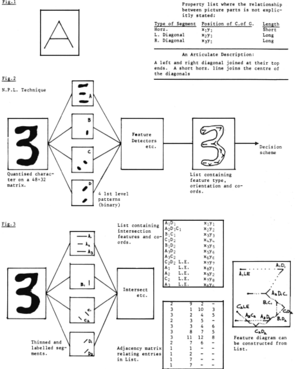
The distinction made between articulate descriptions and property or attribute lists is sometimes rather pedantic. A property or attribute list containing, say, feature detector responses, and the spatial co-ordinates of these responses, could be said to be an articulate description in the sense that the relationship between various attributes is implicit in the spatial co-ordinates associated with these attributes . The structural information which is explicitly stated in an articulate description may be buried in a property list . It is a difference in representation of information rather than a difference in information content, albeit that this difference may be very impor tant. This point is illustrated in Fig.l.
Thus , a structural or articulate descrip t ion can be generated from some property lists whi ch are seen in this context as a convenient intermediate step between the pattern and the production of an articulate description. This is t he philosophy underlying the approach des cribed here, in particular a method to reduce hand-printed characters to a graph-representable fo rm, where area zoning techniques and descrip ti ve techniques can be applied.
2. ~o t i vation
The work described here is a prelimi nary invest i gati on into an extension of a technique developed at the ~ational Physical Laboratory , England. A brief description of the N. P.L. techn ique is given here. A full description wi ll be found in reference (8).
Ct ~racters are first 'scanned by a flying s po t scanner and quantized on to a 48 · 32, 3-b it gray scale matrix. This analogue matrix is then converted into 4 binary matrices, which i deally represent the horizontal, vertical and ri gh t and left diagonal components of the pattern. Feature extractors are applied to these patterns, referred to as lst level patterns, and features of four generic t ypes, (1) line endings, (2) changes of dire cti on (j unc ti on of 2 lines), (3 ) line junctions (junctions of 3 lines), and (4 ) crossovers, (juncti ons of 4 lines), are detected in different orientations, defining approximately 64 features. A list is produced containing the de tected features and the co-ordinates on which they occur. This is shown schematically in Fig.2. A hierarchical decision scheme looks for certain spatial juxtapositions of features, and eventually selects a character class to wh i ch t he feature list conforms.
lnforma~ion not eval uated or expli c itly used in the N.P.L . technique is the connectivity relationship between features . For example, having found a line ending, say the upper L.H. line ending in Fig.2, the fact that this fea ture and the upper R.H. acute angle are both end features of the same horizontal line is regained in the decision scheme by lookiug for a feature to the right of the line ending.
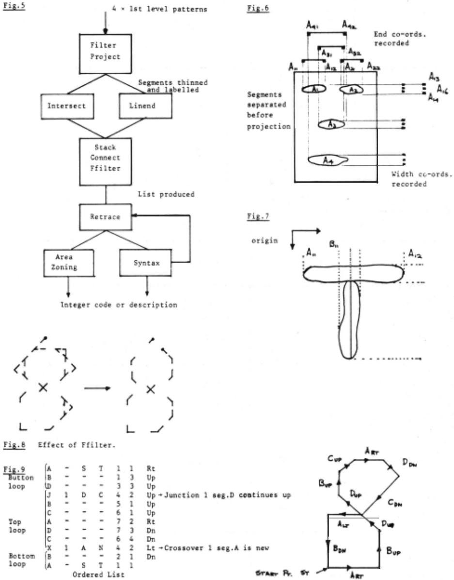
An alternative approach, wQich is the subject of this paper, is to generate a list which consists of the intersections between labelled segments in the 1st level patterns. The segments can be easily thinned if one exploits the fact that a pattern should only consist of either horizontal, vertical or diagonal lines. The feature type information and the connectivity information is implicit in the list in Fig.3 (hereinafter referred to as List). For example, the information that the top R.H. feature, A1D1, is an acute change of direction with a certain orientation as opposed to any other combinat i on of a hori zontal and right diagonal line, is given by the existence of only two other connected features, A1LE (AI line ending), A2C1D1 and the spatial position of these. An advantage of this method i s that it is not necessary to search for a large number of different features. If no vertical segments exist, then no vertical intersections are searched for. Having gener ated List, it is a fairly simple matter to start at a line ending, or at the lowest or highest feature if no line ending exists, and to generate a list, Fig.9, which consists of the segments passed, their start points and the direction travelled - up, down, left or right. This list is referred to as Ordered List. The segments will either appear con secutively, in the order in which they would have been generated by hand, or, the sequence will bear some relation to this order. The starting point is unimportant . In this form the character representations are suitable for parsing into a descriptive sentence or for the application of area zoning techniques.
3. Pre-processing method
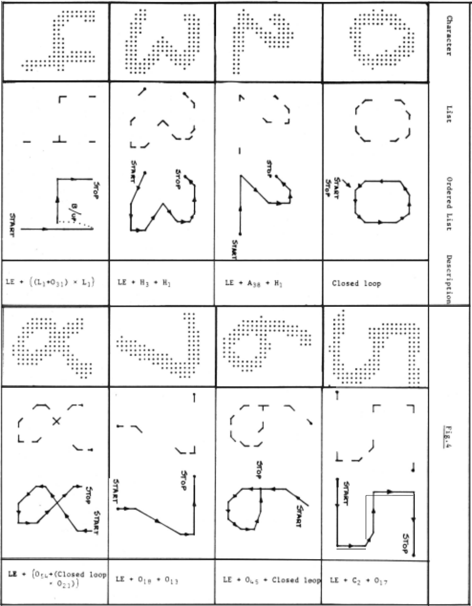
This section contains a brief description of the pre-processing method . The technique is si m~lated in a computer program; a sample comprising of 250 (25 per class), unconstrai ned hand-printed numerals were obtained from the N. P. L. already dichotomized into horizontal , vertical and le f t and right diagoual lst level features. The method is still being optimized on the design set, and the amount of data processed is limited. Some results are illus trated in Fig.4, and it is hoped that results from long runs will be available in time for the Conference. A block schematic diagram of the pre-decision stages in terms of the program sub-routines is given in Fig.5, and it is con venient to explain the method in terms of
these routines.
(a) Filter
This routine removes isolated points from each 1st level pattern. A point is considered to be isolated if there are no points immediatelv adjacent to it, in a direction specified by the type of 1st level pattern to which the point belongs. For example, a point in the horizontal 1st level pattern which does not have a point immediately to the right or left of it is remove~
(b) Project
The aim is to label and obtain a co ordinate representation of each segment. A convenient way to accomplish this is to separate the segments and project them horizontally and vertically, at the same time maintaining the separation between segments. This is shown for a horizontal pattern in Fig.6. Five co-ordinates specify a horizontal line, (and similarly a vertical) ANI· AN2· AN3· AN~ and AN s· A similar procedure is adopted for the diagonals - but only four co-ordinates are specified.
(c) Intersect
This routine checks for intersections of labelled lines representing segments from pairs of 1st level patterns, by comparing their co ordinates. For example, the junction in Fig.7 is detected as the intersection feature A1B1 occurring as co-ordinates A1c BIC· viz. A1B1 occurs on co-ordinates A1c B1c
Tolerances are allowed in the expressions. The process is equivalent to simply over-laying the four thinned and labelled 1st level patterns, and specifying a feature where an intersection occurs, or occurs after allowing for the toler ances.
(d) Linend
Any segment which does not have a feature within a reasonable distance of an extremity is allocated a line ending at that extremity. Unfortunately, this has the effect of occasion ally generating line endings where none are wanted, and the criteria used in this routine are being re-examined.
(e) Stack
Features which occur at the same co ordinates are combined, for example, A1B1 and A1C1 both at point X,Y. This is re-written as A1B1C1, ~epresenting a 3-way junction.
(f) Connect
As stated in section 2, a list, termed List, is built up of suffixed intersection features. The generic type is given by the letters in List. The particular variety of type, i.e. whether an AB intersection is a corner,junction or crossover, although not explicitly stated in List, is embedded in List in the form of connectivity relationships, wherein features are related by their numerical suffices. The connectivity between features is expressed in a matrix, termed an adjacency matrix- Fig.3. This is evaluated by first constructing a connectivity matrix which connects entries in List if they share a common letter and suffix. The connectivity matrix is degener ated into an adjacency matrix by selecting only those connections which link a feature to its nearest neighbour. In Fig.3, A3D2 connects to C2D2, B1D2, C1D2 and A3C2, but is only adjacent to C2D2, B1D2 and A3C2. Each row corresponds to a row in the List. The first number in each row is the number of connections in the row and the other numbers give the entry in the list to which the feature is connected.
(g) Ffilter (feature· filter)
Usually a number of redundant links appears in List. By far the most numerous form triangles, Fig.B, with a feature at each vertex. These are simply eliminated by looking for triangular relationships and eliminating the links which only contribute to the formation of a triangle if the area of the triangle is less than a fraction of the area occupied by the character. It is not strictly necessary to eliminate these redundancies, although there are certain advantages in doing so. These are explained in the next paragraph.
(h) Retrace
This routine traces through List and produces Ordered List, consisting of segment type, line endings, junctions, crossovers, the co-ordinates of the start point of each segment, and the direction of the segment relative to the trace. A trace continues until a line end ing is encountered, or until the starting point is regained. If no untraced segments remain, trace stops. If untraced segments connected to the line ending remain, then the trace backs up and continues. Since the routine has to make a decision on encountering a line ending, whether any untraced segments are redundant or not, it is clearly desirable to remove redundancies generated by the intersection process, and this is the purpose of the previous routine, Ffilter. A trace will also terminate at a junction encountered for the second time (unless it is a crossover). This signifies a closed loop. An example is shown in Fig.9. The start co ordinates of each segment are in columns 5 and 6, and the direction taken by the segment in column 7. The segments are in columns 1 or 3; junctions are numbered J1, J 2, etc., and if encountered twice x1, x2· Jl AN means junction no. 1 is encountered, the previous segment terminates at that junction and A is new. Jl AC means A continues. On encountering a junction the trace will try to keep in the same direction as the previous segment. A trace starts at a line ending if a line ending is the lowest or highest feature or if it is connected directly to the lowest or highest features, otherwise it starts at the lowest feature. 2-stroke charac ters are identified by the existence of 2 line endings separated from the rest of the character already traced, and another trace is initiated. At junction points where there is a choice in the next segment to be selected, the decision is based on the direction of the previous segment. Results for samples of eight numerals are shown in Fig.4.
4. Decision techniques
(i) Area zoning
The information is now in a suitable form for direct application of area zoning techniques, and work is continuing on this. Area zone techniques produce a very basic structural description of the character. If the produced code is unenhanced by the addition of any information other than position, then the character is represented by a directed graph whose points occur (somewhere) in each zone. Such techniques are extremely simple, and a large number of hand-written characters will map into identical codes, although 40-50 codes may be required to specify a character class. Inevitably there is a reject category for
'unseen' codes.
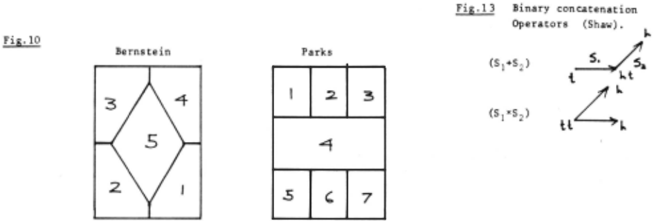
The co-ordinate information in columns 5 and 6 of Ordered List may be insufficient if used on its own. In particular, a long vertical line spec ified by its end co-ordinate could "miss" a central zone. It is intended to imple ment two schemes and these are shown in Fig.lO. One is due to Bernstein, (8) and the other to Parks,C6l. Bernstein uses a local velocity to detect corners and his code consists of the area sequence plus corner information, and is an enhanced area zone technique. In this method corner information is available from the segment type information in Ordered List.
(ii) Syntax directed approach
Syntax directed approaches are being increasingly used in picture interpretation. It is worth re-emphasizing at this point that an articulate description may not be required in a 'passive' recognition situation, where it is required to map a character into a finite number of classes. Articulate descriptions are required when it is necessary to interrogate the descrip tion with such questions as:
In what sense is q different from Cf? Is ~ more like a nine or a five?
However, a formal descriptive approach may prove a more useful technique than an area zone code.
The degree of articulation or detail in the description can be changed, although it is unlikely that the number of descriptive sen tences produced for a given set of examples of a class will be much less than with the area zone codes - an area zone code is a very basic structural description. A formal descriptive approach may give rise to fewer ambiguities (characters from different classes producing the same description), and it should be easier to resolve the ambiguities when the structural information is presented in a sentence.
The basis of these approaches is that a picture can be described in terms of primitive components or entities, such as line segments (in this case). The picture or character can be broken down into related structures and these structures into primitive components or entities (which cannot be further articulated). This process is directed by a set of rewrite rules or syntax in the same way that sentences can be broken down into phrases and words. Pictorial relationships relating parts of a character may be "near to", "above", "left of", "joining", etc.
Primitives may be related to other pr4m4tives to form higher level structures and these related to form further structures, and even tually the character. The main pre-requisite of this approach is that the character is in a form Whereby the primitives and their relation ship to each other is easily recoverable under the direction of the rewrite rules. The problem is somewhat simpler in the case of 'on-line' characters, and it has been shown that infor mation bearing some resemblance to real time information can be obtained from List.
Shaw defines pictures in terms of primi~ tives which, in this case, are either segments or groups of segments. A full definition is given in reference (9), and definitions relevant to this application are reproduced here for convenience.
- A picture primitive has two dis tinguished points, a tail and a head.
- Primitives can only be geometrically concatenated together at their tail and head points (h and t).
- Four binary concatenation operations are defined. These are illustrated in Fig.l3.
- Primitives are grouped into higher level structures by specifying a grammar G generating sentences in the picture description language, describing the picture of interest. G is a context-free phrase structure grammar.
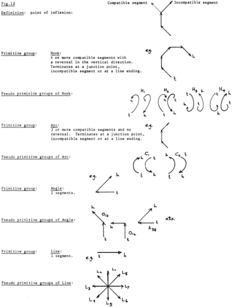
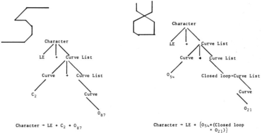
Only the+ and X operators are used in this context; these are pictorial relationships of the form "joined to". An immediate disadvantage is the restriction of primitives (or groups of primitives) relating to other primitives only at their head and tail points. Thus, such charac ters as 4 necessarily break into ~- and the result is an "unappealing" description. The advantage of this metho~ is its extreme sim plicity and ease of implementation on the data in List. The syntax used is illustrated in Fig.ll, and primitive groups in Fig.l2.
| Characters are | assumed to consist of: |
|---|---|
| L.E. line endings Line Closed loop Hook Arc Angle | Primitives Primitive groups |
Primitive groups are groups of line segments which need not be articulated into parts. Thus, a closed loop, hook, arc or angle are not further articulated into their constituent line segments. L1-Le are pseudo primitives,in the sense that the suffices merely specify the attribute direction (Fig.l2) of the line, rather than defining new primitives. In the same way, the suffices of the pseudo pr1m1t1ve groups specify the orientation of the primitive groups. These definitions reflect an extremely simple formation expressible in terms of a syntax. A character representation can then be parsed, as shown in Fig.ll, under the direction of these rules.
Shaw outlines the advantages of using a top down parser in picture interpretation, but the nature of the data and the form of the re write rules suggest a bottom up parsing pro cedure. The parsing algorithm used is simply a modification of the routine Retrace, (already described) which traces line segments until a junction point or point of inflexion is reached, and then classifies or "attributizes" the primitive or primitive group into pseudo primitives or pseudo primitive groups. Results are shown for eight numerals in Fig.4; 2-stroke characters have not yet been dealt with. Shaw suggests the use of a blank primitive.
5. Results
250 characters have been processed and about 15% of the processed characters are unsuitable for the application of the above two techniques. This is either due to spurious line endings generated in the routine Linend, or extra unwanted features which cannot be eliminated by Ffilter, arising from too much detail in the process which produces the 1st level features. Both these processes are being re-designed.
6. Conclusions
- A method has been described which,
- forms four sets of directionally oriented segments by mapping points into these segments which have a particular relationship with neighbour ing points;
- numbers or labels the constituent segments;
- finds intersection features, which are connected to each other by the labelling, by using nearness and inter section criteria to relate segments;
- uses the implicit connectivity between the features to either
- (a) reconstruct a representation of the character which bears a simple relationship to the information obtainable from "on-line" characters, or
- (b) use in a sintax-directed approach.
Experience gained so far has proved encouraging, although certain difficulties are becoming apparent. In particular, the primitive definitions and primitive grouping may have to be re-examined; the present sche~~ produces some descriptions which are not intuitively appealing.
7. References
- Rohland et al, "The design of an O.C.R. system for reading handwritten numerals" A.F.I.P.S., Conf. Proc . , Vol.33, Pt.2, 1968, pp 1151-1162.
- Greanias et al, "The recognition of hand written numerals by contour analysis" I.B.M. J. of Res. and Dev., Vol. 7, Jan. 1963, pp 14-21.
- Munson, J. H. "Experiments in the recog nition of handprinted text" A.F.I.P.S., Conf. Proc., Vol.33, Pt.2, 1968, pp 11251149.
- Nagy and Tuong, "Normalization techniques for handprinted numerals" I.B.M. J. of Res. and Dev., Vol.l3, No.8, Aug.l970, pp 475-481.
- Casey, R. G. , "Movement normalization of handprinted characters" I. B. M. J. of Res. and Dev., Vol.13, Sept.l970, pp 548-557.
- Parks, J. R., private communication.
- Bernstein, M. I., "A method for recog nizing handprinted characters in real time" Pattern Recognition, Academic Press, 1968, pp 109-114.
- Parks, J. R., "A multi-level system of analysia for mixed font and hand block printed character recognition" Automatic Interpretation and Classification of Images, Academic Press, 1969, pp 295-322.
- Shaw, A. C., "Parsing of Graph Representable Pictures" J.A.C.M., Vol.l7, No.3, July 1970, pp 453-481.
·~
.s '
Character ~ LE + Curve List I Curve List
Curve List ~ Closed loop e Curve List i Curve ~ Curve List I Closed loop
Curve ~ Hook I Arc I Angle I Line
(where ¢ is + or x)
Curve
Orientation attributes represented as ~ewrite rules producing pseudo primitives
Hook
Arc Angle ... etc.
Line
E.G .
@inproceedings{ijcai1971p32,
  title     = {Recognition of Hand-Printed Numerals Reduced to Graph-Representable Form},
  author    = {Watt, A. H. and Beurle, R. L.},
  booktitle = {Proceedings of the Second International Joint Conference on
               Artificial Intelligence, {IJCAI-71}},
  publisher = {International Joint Conferences on Artificial Intelligence},
  editor    = {D.C. Cooper},
  pages     = {322--331},
  year      = {1971},
  url       = {https://ijcai.org/proceedings/1971/32},
}
TY - CPAPER TI - Recognition of Hand-Printed Numerals Reduced to Graph-Representable Form AU - Watt, A. H. AU - Beurle, R. L. T2 - Proceedings of the Second International Joint Conference on Artificial Intelligence, IJCAI-71 PB - International Joint Conferences on Artificial Intelligence PY - 1971 SP - 322 EP - 331 UR - https://ijcai.org/proceedings/1971/32 ER -Copied
Machine-readable versions of this paper, for tools and AI agents:





