LADDER: A Language to Describe Drawing, Display, and Editing in Sketch Recognition
Proceedings of the Eighteenth International Joint Conference on Artificial Intelligence. Pages 461-466.
© 2003 International Joint Conferences on Artificial Intelligence
Abstract
We have created LADDER, the first language to describe how sketched diagrams in a domain are drawn, displayed, and edited. The difficulty in creating such a language is choosing a set of predefined entities that is broad enough to support a wide range of domains, while remaining narrow enough to be comprehensible. The language consists of predefined shapes, constraints, editing behaviors, and display methods, as well as a syntax for specifying a domain description sketch grammar and extending the language, ensuring that shapes and shape groups from many domains can be described. The language allows shapes to be built hierarchically (e.g., an arrow is built out of three lines), and includes the concept of "abstract shapes", analogous to abstract classes in an object oriented language. Shape groups describe how multiple domain shapes interact and can provide the sketch recognition system with information to be used in top-down recognition. Shape groups can also be used to describe "chain-reaction" editing commands that effect multiple shapes at once. To test th at recognition is feasible using this language, we have built a simple domain-independent sketch recognition system that parses the domain descriptions and generates the code necessary to recognize the shapes.
- [Alvarado eta!., 2002] C Alvarado, M Oltmans, and R Davis. A framework for multi-domain sketch recognition. AAAI Spring Symposium on Sketch Understanding, pages 1-8, March 25-27 2002. [Bimber eta/., 2000]
- Bimber, LM Encamao, and A Stork. A multi-layered architecture for sketch-based interaction within vir- tual environments. Computer and Graphics, 2000.
- [Booch eta/., 1998] G Booch, J Rumbaugh, and I Jacobson. The Unified Modeling Language User Guide. Addison-Wesley, Read- ing, MA, 1998.
- [Caetano eta/., 2002] A Caetano, N Goulart, M Fonseca, and J Jorge. Javasketchit: Issues in sketching the look of user inter- faces. AAAI Spring Symposium on Sketch Understanding, 2002.
- [Friedman-Hill, 1995] E Friedman-Hill. Jess, the rule engine for the java platform. http:/ lherzberg.ca.sandia.gov/jess/, 1995. Link
- [Gips, 1999] J Gips. Computer implementation of shape grammars. NSF/MIT Workshop on Shape Computation, 1999.
- [Gross and Do, 1996] MD Gross and EYL Do. Demonstrating the electronic cocktail napkin: a paper-like interface for early design. ACM Conference on Human Factors in Computing, pages 5--{) 1996. ,
- [Hunt and McGlashan, 2002] A Hunt and S McGlashan. Speech recognition grammar specification version 1.0, w3c candidate re- comentation. http://www.w3 .org/TR!speech-grammar, 26 June 2002. Link
- [Jacob eta/., 1999] RJK Jacob, L Deligiannidis, and S Morrison. A software model and specification language for non-WIMP user interfaces. ACM Transactions on Computer-Human Interaction, 6(1):1-46, 1999.
- [Mahoney and Fromherz, 2002] N Mahoney and MPJ Fromherz. Three main concerns in sketch recognition and an approach to ad- dressing them. AAAI Spring Symposium on Sketch Understand- ing, pages 105-112, March 25-27 2002.
- [Sezgin eta!., 2001] TM Sezgin, T Stahovich, and R Davis. Sketch based interfaces: Early processing for sketch understanding. Per- ceptive User Interfaces Workshop, 2001.
- [Sez~in, 2002] M Sezgin. Generating domain specific sketch recog- mzers from object descriptions. MIT Student Oxygen Workshop, 2002.
- [Stiny and Gips, 1972] G Stiny and J Gips. Shape grammars and the generative specification of painting and sculpture. Informa- tion Processing, pages 1460-1465, 1972.
- [Veselova, 2002] Veselova. Perceptually based learning of shape descriptions from one example. MIT Student Oxygen Workshop 2002. ' Zue eta/., 1990]
- V Zue, J Glass, M Phillips, and S Seneff. The mit speech recognition system: phonological modeling and lexical access. 1990 International Conference on Acoustics, Speech and Signal Processing, pages 49-52, March 25-27 1990.
References were extracted automatically from the PDF and may contain errors.
Full text extracted automatically from the PDF; figures, tables and equations may differ. The PDF is the version of record.
1 Introduction
To date, sketch recognition systems have been domain specific, with the recognition details of the domain hard coded into the system. Developing such a sketch interface is a substantial effort. We propose instead that recognition be per formed by a single domain-independent recognition system that uses a domain specific sketch grammar (an approach used with some success in speech recognition [Zue et al., 1990; Hunt and McGlashan, 2002]). Programmers could then cre ate new sketch interfaces simply by writing a sketch grammar describing the domain-specific information.
We have created LADDER, a sketch description language that can be used to describe how shapes and shape groups are drawn, edited, and displayed. These descriptions primarily concern shape, but may include other information helpful to the recognition process, such as stroke order or stroke direc tion. The specification of editing behavior allows the system to determine when a pen gesture is intended to indicate edit ing rather than a stroke. Display information indicates what to display after strokes are recognized.
The language consists of predefined shapes, constraints, editing behaviors, and display methods, as well as a syntax for specifying a domain description and extending the lan guage. The difficulty in creating such a language is ensur ing that domain descriptions are easy to specify, and that the descriptions provide enough detail for accurate sketch recognition. To simplify the task of creating a domain de scription, shapes can be built hierarchically, reusing low level shapes. Shapes can extend abstract shapes, which de scribe shared shape properties, preventing the application de signer from having to redefine these properties several times. The language has proven powerful enough to describe shapes from several domains. The language enables more accurate sketch recognition by supporting both top-down and bottom up recognition. Descriptions of how shapes may combine can aid in top-down recognition and can be used to describe "chain-reaction" editing commands.
Our contribution is in creating LADDER, the first sketch ing language to incorporate editing, display, and shape group information. To test our language, we have built a simple domain-independent sketch recognition system that parses the domain description and successfully recognizes shapes based on these descriptions.
Section 2 describes the components of the language, in cluding the predefined shapes, constraints, editing behaviors, and display methods available. Section 3 describes the syn tax and content of a sketch grammar designed in the language. Section 4 describes a system we have implemented to test the language and ensure that shapes in a domain can be recog nized based on their descriptions. Section 5 describes related work done in the development in sketch languages.
2 Language Contents
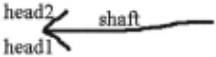
The language consists of predefined shapes, constraints, edit ing behaviors, and display methods. Figure 2 shows an ex ample description for OpenArrow drawn in (Figure 1 ). The description of a shape contains a list of components (the el ements from which the shape is built), geometric constraints on those components, a set of aliases (names that can be used to simplify other elements in the description), editing behav iors (how the object should react to editing gestures), and dis play methods indicating what to display when the object is recognized.
(define shape OpenArrow (description "An arrow with an open head") (components (Line shaft) (Line headl) (Line head2)) (constraints (coincident shaft.pl headl.pl) (coincident shaft.pl head2.pl) (coincident headl.pl head2 .pl) (equal-length headl head2) (acute-meet headl shaft) (acute-meet shaft head2)) (aliases (Point head shaft .pl) (Point tail shaft .p2)) (editing ( (trigger (click_hold_drag shaft)) (action (translate this) (set-cursor DRAG) (show-handle MOVE tail head))) (trigger (click_hold_drag head)) (action (rubber-band this head tail) (show-handle MOVE head) (set-cursor DRAG))) (trigger (click hold drag tail)) (action - - (rubber-band this tail head) (show-handle MOVE tail) (set-cursor DRAG)))) (display (original-strokes)))The power of the language is derived in part from carefully chosen predefined building blocks.
2.1 Predefined Shapes
The language includes a number of predefined primitive and non-primitive shapes, usable as building blocks in describing other shapes. The primitive shapes are Shape, Point, Path, Line, BezierCurve, and Spiral. Circle, Arc, and Ellipse are examples of non-primitive shapes included in the language library; all three are more specific versions of the primitive shape Spiral. The OpenArrow in Figure 2 is a non-primitive shape built out of three primitive shapes.
The language uses an inheritance hierarchy; Shape is an abstract shape which all other shapes extend. Shape provides a number of components and properties for all shapes, includ ing boundingbox, centerpoint, width, and height. Each prede fined shape may have additional components and properties; a Line, for example, also has pi, p2 (the endpoints), midpoint, length, angle, and slope. Components and properties for a shape can be used hierarchically in shape descriptions. When defining a new shape the components and properties are those defined by Shape, and those defined by the components and aliases section.
2.2 Predefined Constraints
New shapes are defined in terms of previously defined shapes and constraints between them. For instance, the OpenArrow in Figure 2 contains the constraint (acute-meet head] shaft), which indicates that head] and shaft meet at a point and form an acute angle in a counter-clockwise direction from headl to shaft. (Angles are measured in a counter-clockwise direc tion.)
A number of predefined constraints are included in the lan guage, including: perpendicular, parallel, collinear, same side, opposite-side, coincident, connected, meet, intersect, tangent, contains, concentric, larger, near, draw-order, equal length, =, <, <=, angle, angle-dir, acute, obtuse, acute meet, and obtuse-meet. If a sketch grammar consists of only the constraints above, the shape is rotationally invariant.
There are also predefined constraints that are valid only in a particular orientation, including horizontal, verti cal, pos-slope, neg-slope, left-of, right-of, above, below, same-H-pos, same-V-pos, above-left, above-right, below-left, below-right, centered-below, centered-above, centered-left, centered-right, and angleL, where (angleL line] degrees) specifies that the angle between a horizontal line pointing right and linel is degrees.
There is an additional constraint: is-rotatable, which im plies the shape can be found in any orientation. If is-rotatable is specified along with an orientation-dependent constraint, there must be an angleL, horizontal, or vertical constraint specified, which serves to define the orientation and set a rel ative coordinate system. For example, the two angle-meet constraints could have been replaced with:
(is-rotatable} (horizontal shaft) (neg-slope headl) (poe-slope head2) (left-of shaft . pl shaft.p2) (left-of headl.p2 shaft.p2) (left-of head2 .p2 shaft .p2) ,
in which case the shaft is the reference line.
2.3 Predefined Editing Behaviors, Actions, and Triggers
Describing editing gestures permits the recognition system to discriminate between sketching (pen gestures intended to leave a trail of ink) and editing gestures (pen gestures in tended to change existing ink), and permits us to describe the desired behavior in response to a gesture.
In order to encourage interface consistency, the language includes a number of predefined editing behaviors described using the actions and triggers above. One such example is Draglnside, defines that if you click-hold-drag the pen start ing inside of the bounding box of a shape, the entire shape automatically moves with it.
When defining a new editing behavior particular to a do main, there are two things to specify: the trigger- what sig nals an editing command- and the action- what should hap pen when the trigger occurs. The language has a number of predefined triggers and actions to aid in describing editing behaviors.
For instance, in Figure 2, the OpenArrow contains three editing behaviors. The first editing behavior says that if you click and hold the pen over the shaft of the OpenArrow, when you drag the pen, the entire OpenArrow will translate along with the movement of the arrow. The second editing be havior states that if you click and hold the pen over the head of the arrow, the head of the arrow will follow the motion of the pen, but the tail of the arrow will remain fixed and the entire OpenArrow will stretch like a rubber band (translat ing, scaling, and rotating) to satisfy these two constraints and keep the OpenArrow as one whole shape. All of the edit ing behaviors also change the pen's cursor as displayed to the sketcher, and display moving handles to the sketcher to let the sketcher know that she performing an editing command.
The possible editing actions include wait, select, deselect, color, delete, translate, rotate, scale, resize, rubber-band, show-handle, and set-cursor. To give an example:
(rubber-band shape-or-selection fixed-point move-point [new-point])
translates, scales, and rotates the shape-or-selection so that the fixed-point remains in the same spot, but that the move-point translates to the new-point. If new-point is not specified, 'move-point translates according to the movement of the pen.
The possible triggers include: click, double-click, click hold, click-hold-drag, draw, draw-over, scribble-over, and encircle. Possible triggers also include any action listed above, to allow for "chain-reaction" editing.
Shape groups allow designers to define "chain-reaction" editing behaviors. For instance, the designer may want to specify that when we move a rectangle, if there is an arrow head inside of this rectangle, the arrow should move with the rectangle.
2.4 Predefined Display Methods
An important part of a sketching interface is controlling what the user sees after shapes are recognized. The designer can specify that the original strokes should remain, or instead that a cleaned version of the strokes should be displayed. In the cleaned version, the original strokes are fit to straight lines, clean curves, clean arcs, or a combination.
Another option is to display the ideal version of the strokes. In this case, lines that are supposed to connect at their end points actually connect and lines that are supposed to be par allel are actually shown as parallel. In the ideal version of the strokes, all of the noise from sketching is removed.
It may be that we don't want to show any version of the strokes at all, but some other picture. In this case, we can ei ther place an image at a specified location, size, and rotation, or we can create a picture built out of predefined shapes, such as circles, lines, and rectangles.
The pre-defined display methods include: original-strokes, cleaned-strokes, ideal-strokes, circle, line, point, rectangle, text, color, and image. Each method includes color as an op tional argument.
3 Specifying a Domain Description
A domain description contains a list of the domain shapes and shape groups, as well as definitions for each of them. De scriptions can be hierarchical and can refer to other shapes in the language. This section provides examples from the domain description sketch grammar of UML (Unified Mod elling Language) class diagrams [Booch eta/., 1998].
3.1 Indicating Domain Definitions
The compiler uses a list of domain shapes and shape groups to confirm that each shape is properly defined and to speed recognition by creating recognizers only for sub-shapes needed by the domain.
3.2 Defining Shapes
A domain shape is a shape that is meaningful in the do main. Geometric shapes usually occur in several domains and are the building blocks of the domain shapes. For instance, in the domain of UML class diagrams, the domain shapes (followed by their geometric shape component) are: general classes (represented by rectangles), interface classes (circles), interface associations (lines), dependency associations (open headed arrows), aggregation associations (diamond-headed arrows), inheritance associations (triangle-headed arrows), information associations (dotted lines or dotted open arrows).
A shape definition includes primarily geometric informa tion, but can include other drawing information that may be helpful to the recognition process, such as stroke order or stroke direction. A shape definition is composed of seven sections. All sections are optional except the components sec tion.
- The description contains a textual description of the shape, e.g., "an arrow with a triangle-shaped head."
- The is-a section specifies any class of abstract shapes (Section 3.3) that the shape may be a part of. This is similar to the extends property in Java. All shapes extend the abstract shape Shape.
- The components section lists the components of the shape. For example, the TriangleArrow in Figure 3 is built out of the OpenArrow from Figure 2 and a Line. Components can be accessed hierarchically.
- The constraints section specifies relationships between the components. For example, in the TriangleArrow in Figure 3, (coincident head3.pl headl.p2) specifies that an endpoint of head3 and an endpoint of head] are lo cated at the same point.
The constraints section can specify both hard con straints, such as the one listed above, and soft con straints, which are specified by the keyword soft. Hard constraints are always satisfied in the shape, but soft con straints may not be. Soft constraints can aid recognition by specifying relationships that usually occur. For in stance, in Figure 3 the shaft of the arrow is commonly drawn before the head of the arrow, but the arrow should still be recognized even if this constraint is not satisfied.
- The aliases section allows us to compute certain prop erties and name them for use later. For instance, in Fig ure 3, head] is defined and used in a constraint for sim plicity. Components specified in the aliases section can be accessed hierarchically. For instance, TriangleAr row uses head and tail from the OpenArrow in Fig ure 2.
- An editing section specifies how the shape can be edited. Common editing commands involve movement
and deletion of the shape. Each editing behavior must specify a trigger and an action listed in Section 2.3.
Shapes can be defined to be moved as a whole rather than having to move individual lines. For instance, in Figure 3, one editing behavior for the TriangleArrow indicates that if the user presses and holds the pen on the shaft for a brief period, the pen will drag the entire TriangleArrow when moved.
- A display section specifies what should be displayed on the screen when the shape is recognized. This section is generally included only for domain shapes, not for ge ometric shapes. In the UMLinheritanceAssociation in Figure 4, the arrow will be displayed using straight lines for the arrow head and the original stroke for the shaft.
(define shape TriangleArrow (description "An arrow with a triangle-shaped head") (components (OpenArrow oa) (Line head3) ) (a liases (Line shaft oa.shaft) (Line headl oa.headl) (Line head2 oa.head2) (Point head oa.head) (Point tail oa.tail)) (constraints (coincident head3.pl headl.p2) (coincident head3.p2 head2.p2) (soft draw-order shaft headl) (soft draw-order shaft head2)) (editing ( (trigger (click_hold_drag shaft)) (action (translate this) (set-cursor DRAG) (show-handle MOVE tail head))) ... ))(define shape UMLinheritanceAssociation (is -a UMLGeneralAssociation) (components (TriangleArrow arrow)) (aliases (Point head arrow.head) (Point tail arrow.tail) (Line shaft arrow.shaft)) (display (original_strokes arrow .shaft ) (c leaned_strokes arrow.headl arrow . head2 arrow.head3))3.3 Defining Abstract Shapes
In the UMLinheritanceAssociation defined in Figure 4, the is-a section specifies that the UMLinheritanceAssociation is an extension of the abstract shape UMLGeneralAssocia tion. Abstract shapes have no concrete shape associated with them; they represent a class of shapes that have similar at tributes or editing behaviors. These attributes can be defined once in the abstract shape description rather than for each do main shape. For instance, in Figure 2 and Figure 3, notice that the OpenArrow and the TriangleArrow have identical edit ing behaviors defined. Rather than repeatedly listing these editing behaviors in each shape, we could create an abstract shape which specifies these editing behaviors.
An abstract shape is defined similarly to a regular shape, except it has a required section instead of a components sec tion. Each shape that extends the abstract shape must define each variable listed in the required section, in its components or aliases section.
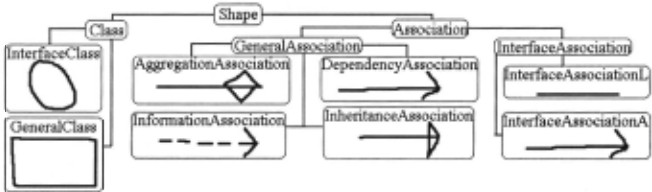
Figure 5 presents a diagram of the inheritance hierarchy for the abstract and non-abstract shapes in the UML class dia grams domain. In UML, UMLDependencyAssociation, the UMLinheritanceAssociation, the UMLAggregationAsso ciation, the UMLinformationAssociation, and the Inter faceAssociation are all links represented by arrows or lines and all have the same editing behavior. Thus, we can create the abstract shape UMLAssociation, which lists the editing behavior of these shapes. Figure 6 shows the abstract shape description of the UMLAssociation. Notice that the required variables are used when defining editing behaviors.
(define abstract-shape UMLAssociation (is-a Shape) (required (Point head) (Point tail ) (Line shaft)) (editing ( (trigger (click_hold_drag shaft)) (action (t ranslate this) (set-cursor DRAG) (show-handle MOVE tail head))) . .. ))Figure 6: The description for the abstract class UMLAssoci ation.
3.4 Defining Shape Groups
A shape group is a collection of domain shapes that are commonly found together in the domain. Defining shape groups provides two significant benefits. Shape groups can be used by the recognition system to provide top-down recogni tion, and "chain-reaction" editing behaviors can be applied to shape groups, allowing the movement of one shape to cause the movement of another.
In the domain of UML class diagrams, there are six le gal shape groups that describe the visual relationship between UML associations and UML classes. For example, one shape group consists of an association combined with a general class, such that the tail of the association is inside or near the general class shown in Figure 7 and described in Figure 8. A shape group definition is similar to that of a shape definition.
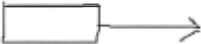
If a single shape in a sketch can be part of many instances of a shape group, then we place the key word multiple before the component shape of the shape group. In UML Class Dia grams, for example, a single UMLAssociation can be part of only one instance of a shape group, while a single UMLClass can be part of many instances ofUMLGenClassGenAssoci ationTail.
(define shape-group UMLGenClassGenAssociationTail (de scription "A general c lass attached to the tail of a general a ssociation") (is - a UMLAssociationAttachedTail) (components (multiple (GeneralClass ct)) (GeneralAssociation r)))3.5 Defining Abstract Shape Groups
Abstract shape groups definitions allow the reuse of shared properties across multiple shape groups. The definition of a UMLAssociationAttachedTail in Figure 9 indicates that the tail, but not the head, of the association is inside the class, preventing us from having to redefine the constraints many times, and allows us to define one general editing behavior for many shapes. An editing behavior for the UMLAssocia tionAttachedTail indicates that whenever you move a UML Class that is attached to the tail of a UMLAssociation, the head of the UMLAssociation remains fixed in its original lo cation, but the tail of the UMLAssociation remains attached to the UMLClass as it moves; the UMLAssociation acts like a rubber band (translating, scaling, and rotating) to satisfy these constraints.
(define abstract-shape-group UMLAssociationAttachedTail (required (Association r) (Class ct)) (constraints (contains ct r . tail) (!contains ct r . head)) (editing (trigger (translate ct)) (action (rubber-band r r . head r.tail))))3.6 Defining Constraints
We believe the language contains sufficient constraints to de fine a broad range of domains. When an additional con straint is needed, it can be defined using a macro facility. The sections of a sketch-constraint definition include description, components, and constraints.
4 Testing
4.1 Examples of Shapes Described in the
Language
We have evaluated the language by showing that it can de scribe a wide variety of symbols from a number of different domains. We have used it to describe over a hundred shapes
(define constraint centered-in (description "Tests if shapel is centered inside shape2") (components (Shape sl) (Shape s2)) (constraints (contains s2 sl) (coincident sl.center s2.center)))from the domains of UML class diagrams, mechanical engi neering diagrams, course of action diagrams, and letters of the alphabet. Illustrative examples are given below.
Polygon
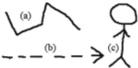
A PolyLine (shown in Figure 11a), may contain a variable number of line segments. A variable number of components is specified by the key word vector and must specify the min imum and maximum number of components. If the maxi mum number can be infinite, the variable n is listed. For in stance the PolyLine must contain at least two lines, and each line must be connected with the previous. The definition of a Polygon easily follows from the definition of the PolyLine
-
(define shape PolyLine (components {vector Line vl[2,n])) (constraints {coincident vl[i) .p2 vl[i+l) .pl)) (aliases (Point head vl [OJ .pl) (Point tail vl [n) .p2))) (define shape Polygon (components (PolyLine poly)) (constraints(coincident poly . head poly.tail)))Figure 12: Shape Description of a Polygon.
Dashed Open Arrow
A DashedOpenArrow (Figure 11b) is made from a Ope nArrow, and a Dashedline, which in turn contains at least two line segments. When given a third argument specifying a length, the constraint near states that two points are near to each other relative to a given length.
Stick Figure
The definition of a stick figure (Figure 11c) shows how we can create new components to help describe shapes. It creates
(define shape DashedLine (c omponent s (vector Line vl [2 , n ] )) (constraints (collinear vl [ i ] .pl vl (i] . p2 vl [i+ll . pl ) { ! (intersect vl [ i] vl ( i+l] ) (near vl [i] . p2 vl [i+ll .pl vl [i] .length )) (aliases (Point head vl [OJ . pl) (Point tail vl [n J . p2)) ) (define shape DashedOpenArrow (components (Ope nArrow oa ) (DashedLine d l )) (const r a i nts (near oa. t a i l dl. head oa.sha ft )) (aliases (Point head oa.head) (Point tai l dl.tail)))a new line between the feet for use in defining constraints, ensuring that both feet lie below the body.
(de f ine s hape Stic kFigure (descri pt i on "a stickf igure with two arms and t wo legs all s l oping down a t 45 degrees") (components (Circle head) (Line body) (Line larm) (Line r a rm) (Line lleg) (Line r l eg)) (al i as (Line fee t space (new Line (lleg .p2 r leg .p2)))) (const r aints (meet head body. pl ) {!{ i n t ersect body head)) (i s- r otatable ) (ver t i cal body) (meet body larm. pl ) (meet body r a r m.p l ) (co i nc i dent l arm.p l r a r m. pl ) (acute larm body) (acute body rarm) (left-of larm r arm) (coincident body. p 2 lleg.pl ) (coincident body.p2 rleg.pl ] (obtuse body lleg) (ob tuse r l eg body ) (perpendi cular larm rarm) (perpendi cular lleg rleg) (near body.pl r arm .pl ) (para llel r a rm rleg ) (parallel larm lleg) ( ! (in tersect f eet s pace body)) (equal - length lleg rleg) - (equal -length larm rarm))4.2 System Implementation
We built a simple domain-independent recognition system to test whether sketches can be recognized from our domain descriptions. The system parses a domain description into Java code and Jess (a rule-based system that interfaces with Java) [Friedman-Hill, 1995] rules, and uses them to recog nize sketches. For example, using the domain description for UML, the system successfully recognized hand-drawn sketches of all of the shapes in Figure 5 regardless of over lap.
Domain Description Parsing
The domain description is parsed to create recognition code, creating at least one Jess rule (containing the shape recogni tion information), and one Java file (describing the shape), for each shape description. The system then uses the Jess rules to recognize sketches.
Jess Rule Example
The rule automatically generated for the TriangleArrow from Figure 3 is shown in Figure 15. If a shape description contains a vector, such as that of the DashedArrow in Fig ure 13, two Jess rules are created, one containing the base case, and the second containing a recursive rule.
Stroke Preprocessing
The recognition system has several stages of recognition. First, each time a stroke is drawn, the stroke is pre-processed [Sezgin et a!. , 2001] into either Point, Line, Curve, Arc, or a combination thereof, allowing users to draw objects in a sin gle stroke or with multiple strokes. These primitive shapes are then asserted to a Jess database.
{defrule TriangleArrowCheck => ;;Get the parts o f the t riangle arrow ? f O <- (Subshapes OpenArrow ?oa $?oa l i st) ?fl <- (Subshapes Line ?head3 $?head3_list ) {OpenArrow ?oa ?oa_shaft ?oa_headl ?oa_head2 ?oa_head ?oa_tail ) (Line ?head3 ?head3_pl ?head3_p2) ;;Make s ure t hat the openarrow and l i ne don't share any subparts. (te s t (uni quefi elds $?oa_list $?head3_list)) ;; Get the subpart of the open arrow since they are referenced (Line ?oa_shaf t ?shaft_pl ?shaft_p2) (Li ne ?oa_headl ?headl_pl ?headl_p2) (Line ?oa_head2 ?head2_pl ?head2_p2) ;; t est for t hat t he cons t rai nts hold (test (co i ncident ?head3_pl ?headl _p2)) (test (coinciden t ?head3_p2 ?head2_p2)) ;; Tr i angle Arrow has been successfully found ; ; Set the aliases (bi nd ?shaf t ?oa_shaft) (bind ?headl ?oa_headl) (bi nd ?head2 ?oa head2) (bind ?head ?oa head) (bind ?tai l ?oa_tai l) - ;; Tell t he recognition s ystem that there is a Triangle Arrow (bind ?nextnum (addshape TriangleArrow ?oa $?head3 list ?shaft ?headl ?head2 ?head ?tail)) - ;; Tell the J ess system that there i s a Triangle arrow (assert (Tr i angleAr row ?nextnum ?oa ?head3 ?shaft ?headl ?head2 ?head ?tail)) (assert (Subshapes TriangleArrow ?nextnum (union$ $?oa_list $?head3_list))) ;; Triangle Arrow is a domai n shape. Assert it . ;; Conflict s will be resolved elsewhere. (ass e rt (DomainShape Tr i angleArrow ?next num (time)) ) (assert (CompleteSubshapes OpenArrow ?oa $?oa_list)))Recognition of Shapes
Recognition is handled by the Jess rule based system. We have automatically generated templates for the Jess system to fill in. Once Jess finds the appropriate components, the rule is fired and the constraints are tested. The constraints are Java functions with which Jess interacts. All possible shapes are found, even if the shapes share lines or other components. If the shape can be a domain shape (i .e., a final shape in the domain), the shape is asserted as a domain shape.
Domain Shapes
When domain shapes are created, a rule fires in Jess confirm ing that no two found domain shapes share the same sub components. If two domain shapes do share subcomponents, one domain shape is retracted. The domain shape chosen to remain is the one containing more primitive components (following Ockham's Razor); if the two shapes contain the same number of components, the shape created first is cho sen, since previously chosen recognitions have higher prece dence. If a domain shape is found, then the recognition sys tem displays the shape as the designer specified and editing commands can then be performed on the shape.
5 Related Work
Shape description languages, such as shape grammars, have been around for a long time [Stiny and Gips, 1972]. Shape grammars are studied widely within the field of architecture, and many systems are continuing to be built using shape grammars [ Gips, 1999]. However, shape grammars were developed for shape generation rather than recognition, and don't provide for non-graphical information, such as stroke order, that may be helpful in recognition. They also lack ways for specifying shape editing.
Within the field of sketch recognition, there have been other attempts to create languages for sketch recognition. Bimber et. a! [2000] describe a simple sketch language using a BNF-grammar. The language describes three-dimensional shapes hierarchically. This language allows a programmer to specify only shape information and lacks the ability to spec ify other helpful domain information such as stroke order or direction and editing behavior, display, or shape interaction information.
Mahoney [2002] uses a language to model and recognize stick figures. The language currently is not hierarchical, mak ing large objects cumbersome to describe. Caetano et. a!. [2002] use fuzzy relational grammars to describe shape. Both Mahoney and Caetano lack the ability to describe editing, dis play, or shape grouping information.
The Electronic Cocktail Napkin project [Gross and Do, 1996] allows users to define domain shapes by drawing them. A shape is described by the shapes it is built out of and the constraints between them. The Cocktail Napkin's language is able to describe only shape.
Jacob [Jacob eta!., 1999] has created a software model and language for describing and programming fine-grained aspects of interaction in a non-WIMP user interface, such as a virtual environment. The language is very low-level making it difficult to define new interactions, and, in the domain of sketching, does not provide a significant improvement to cod ing the domain-dependent recognition system from scratch.
The language described in this paper is being used in sev eral other systems, including sketch learning from example [Veselova, 2002], smart compiling using HMM's [Sezgin, 2002], and an intelligent Bayesian network context oriented sketch recognition system [Alvarado eta!., 2002].
6 Conclusion
6.1 Future Work
We plan to examine more domains to ensure that the language contains the appropriate primitives. We would also like to test our syntax on a wide user base. Large domains benefit from visual diagrams, such as the one in Figure 5. We plan to automatically generate some of these visual diagrams to help with the grammar-writing process.
6.2 Contributions
We have created LADDER, the first language to describe how sketched diagrams in a domain are drawn, displayed, and edited. The language consists of pre-defined shapes, con straints, editing-behaviors, and display methods, as well as a syntax for specifying a sketch grammar and extending the language, ensuring that shapes and shape groups from many domains can be described. The syntax simplifies the defini tion of new shapes by allowing shapes to be built hierarchi cally and by providing abstract shapes to contain common ~hape properties. Shape groups describe how domain shapes mteract, and can provide information to be used in top-down as well as bottom-up recognition. Shape groups can also be used to describe "chain-reaction" editing commands. We have built a simple domain-independent sketch recognition system for testing that recognition is feasible based on the descriptions provided.
Acknowledgments
This work is supported in part by the MIT Oxygen Collaboration. The authors would like to thank Jacob Eisenstein for the name LAD DER and Jacob Eisenstein, Michael Oltmans, Mark Foltz, and Vi neet Sinha for their help in reviewing this paper.
@inproceedings{ijcai2003p69,
  title     = {LADDER: A Language to Describe Drawing, Display, and Editing in Sketch Recognition},
  author    = {Hammond, Tracy and Davis, Randall},
  booktitle = {Proceedings of the Eighteenth International Joint Conference on
               Artificial Intelligence, {IJCAI-03}},
  publisher = {International Joint Conferences on Artificial Intelligence},
  editor    = {Georg Gottlob and Toby Walsh},
  pages     = {461--466},
  year      = {2003},
  url       = {https://ijcai.org/proceedings/2003/69},
}
TY - CPAPER TI - LADDER: A Language to Describe Drawing, Display, and Editing in Sketch Recognition AU - Hammond, Tracy AU - Davis, Randall T2 - Proceedings of the Eighteenth International Joint Conference on Artificial Intelligence, IJCAI-03 PB - International Joint Conferences on Artificial Intelligence PY - 2003 SP - 461 EP - 466 UR - https://ijcai.org/proceedings/2003/69 ER -Copied
Machine-readable versions of this paper, for tools and AI agents: