
Structured Modeling Language for Automated Modeling in Causal Networks
Proceedings of the Sixteenth International Joint Conference on Artificial Intelligence. Qualitative Reasoning and Diagnosis. Pages 1108-1116.
© 1999 International Joint Conferences on Artificial Intelligence
Abstract
The paper presents a structured modeling language (SML) and a relational database framework for specification and automated generation of causal models. The framework describes a relational database scheme for encoding a library of causal network templates modeling the basic components in a modeling domain . SML provides a formal language for specifying models as structured components that can be composed from the basic components. The language enables specification of models as l?arameterized relational queries that can be mstantiated for specific mod el instances. The paper describes an algorithm that , given a library and a sp ec ification, computes a causal model in time and space linear in the number of basic components. Th e algorithm enables model reuse by combining mod el fragments from the template library to compose new models. The present automated modeling approach has been implemented using the structured query language (SQL) and a relational database environment. The approach has been successfully used for modeling an automated work-cell in a real-life digital manufacturing application.
- [Darwiche and Pearl, 1994] A. Darwiche and J. Pearl. Sym- bolic causal networks. In Proceedings of the Twelfth Na- tional Conference on Artificial Intelligence, pages 238-244. AAAI Press/ The MIT Press, 1994.
- [de Kleer and Brown, 1986] J. de Kleer and J.S. Brown. Theories of causal ordering. Artificial Intelligence, 29 :33- 62 , 1986.
- [Dechter and Pearl, 1991] R. Dechter and J. Pearl. Directed constraint networks: A relational framework for causal modeling. In Proceedings, JJCAI-91, pages 1164-1170 , 1991. IJCAI
- [El Fattah and Dechter, 1995] Y. El Fattah and R. Dechter. Diagnosing tree-decomposable circuits. In Proceedings of the Fourteenth International Joint Conference on Artificial Intelligence (JJCAI-95}, Montreal, Quebec, Canada, 1995. IJCAI
- [El Fattah and Provan, 1997] Y. El Fattah and G . Provan. Modeling temporal behavior in model-based diagnosis of discrete-event systems (a preliminary note) . In Working Notes of the Eighth International Workshop on Principles of Diagnosis, pages 43-50, Le Mont-Saint-Michel , France, 1997.
- [El Fattah, 1996] Y. El Fattah. Constraint logic pro- gramming for structure-based reasoning about dynamic physical system. Artificial Intelligence in Engineering, 10(3) :253-264, 1996.
- [Falkenhainer, 1991] B. Falkenhainer. Compositional model- ing: Finding the right model for the job. Artificial Intelli- gence, 51:59-143, 1991.
- [Iwasaki and Simon, 1986] Y. Iwasaki and H.A. Simon. Causality in device behavior. Artificial Intelligence, 29:3- 32, 1986.
- [Koller and Pfeffer, 1997] D. Koller and A. Pfeffer. Object- oriented bayesian networks. In Uncertainty in Artificial Intelligence {UAI-97), pages 302-313, 1997.
- [Kuipers , 1984] B. Kuipers. Common sense reasoning about causality: Deriving behavior from structure. Artificial In- telligence, 24:169-203, 1984.
- [Laskey and Mahoney, 1996] K. B. Laskey and S. M. Ma- honey. Network engineering for complex belief networks. In Uncertainty in Artificial Intelligence (UAI-96}, pages 389-396, 1996.
- [Laskey and Mahoney, 1997] K. B. Laskey and S. M. Ma- honey. Network fragments: Representing knowledge for constructing probabilistic models. In Uncertainty in Arti- ficial Intelligence {UAI-97), pages 334-341, 1997.
- [Maier, 1983] D. Maier. The Theory of Relational Databases. Computer Science Press, Rockville, MD, 1983.
- [Nayak, 1994] P. Pandurang Nayak. Causal approximations . Artificial Intelligence, 70:277-334, 1994.
- [Pearl, 1988] J. Pearl. Probabilistic Reasoning in Intelligent Systems: Networks of Plausible Inference. Morgan Kauf- man, San Mateo, CA, 1988.
- [Provan et al., 1998] G. Provan, Y. El Fattah, and A. Dar- wiche. Using database specifications to automate the di- agnosis of factory automation systems. In Proceedings of the International Automative Manufacturing {JAM) Con- ference, pages 323-328, 1998.
References were extracted automatically from the PDF and may contain errors.
Full text extracted automatically from the PDF; figures, tables and equations may differ. The PDF is the version of record.
1 Introduction
Automated modeling is a key for developing automated reasoning applications in domains such as industrial au tomation and digital manufacturing. The models can be used to support reasoning tasks for two main objecti~es. One to reduce the commissioning time by simulatmg, verifying and validating the intended function of a sys tem before it is built. Two, to reduce downtime after a system is built by diagnosing and identifying fau~ts. Building adequate models is typically a time consummg process involving much iteration and requiring in-depth knowledge of the particular domain.
The models considered here are in the form of causal networks [Pearl, 1988; Dechter and Pearl, 1991; Dar wiche and Pearl, 1994]. Causal networks represent cause and-effect relationships in a system by a directed acyclic graph in which nodes are the variables an_d_ the edges represent direct causal influence. In addttlon to the graph, causal network models include quantification of the causal influence. Bayesian networks [Pearl, 1988] quantify the causal influence by conditional probabilities that are attached to each cluster of parents-child nodes in the network. Here we adopt deterministic quantification in the language of directed constraint networks [Dechter and Pearl , 1991].
The significance of the problem of automated mod eling in causal networks is well-known [Laskey and Mahoney, 1996]. Recently, a number of approaches have been proposed based on object-oriented languages, which allow complex domains to be described in terms of interrelated objects [Koller and Pfeffer, 1997; Laskey and Mahoney, 1997]. The focus of those works is on the representation of probabilistic knowledge as network fragments and not on algorithms for constructing mod els from the knowledge base. The contributions of this paper are a relational framework for encoding the causal relationships in a modeling domain; a language for model specification and an algorithm for constructing causal models.
The paper is organized as follows . Section 2 describes SML relational framework and the concept of a template library. Section 3 gives the model specification language and a detailed example. Section 4 describes the algo rithm for constructing causal models. Sections 5 presents discussion and related work and Section 6 concludes.
2 Structured Modeling Language
SML enables specification of models using a library of basic components. Basic components are the building blocks in a modeling domain. Examples of basic compo nents in the industrial automation domain are a proxim ity switch, a cylinder, a valve, and a solenoid actuator . We start with a set of definitions then formalize our con cept of model library and then give an example.
Definition 1 [Relational Databases] [Maier, 1983] Let U = {U1 , . .. , Un} be a set of attributes, each with an as sociated domain. A relational database scheme R over U is a collection of relation schemes { R 1, R2 , ... , Rp} , where Uf=1 R; = U , and R; :f. Rj, if i :f. j . A relational database d on database scheme R is a collec tion of relations {r1, r 2 , ... , rp} · Each relation r; on re lation scheme R;, written r;(R;), is a set of value tu ples {t1, t 2 , ... , tp} for the attributes in R; from their respective domains, and we write t.X to denote the value assigned by a tuple t to a subset X C R;. A key of a relation r;(R;) is a minimal subset K; of R; that uniquely identifies a tuple within the relation. A foreign key is a set of attributes within one relation that matches the key of some (possibly the same) relation. A relation scheme may cont<j.in more than one key and the keys explicitly listed within a relation scheme are called designated keys. We distinguish one of the desig nated keys as the primary key. To denote the primary key of a relation, we underline the attribute names in the key. Let X and Y be subsets of R; ; we say that a relation r;(R;) satisfies the functional dependency (FD) X ---> Y if for every X-value x, there corresponds only one value for Y, i.e., the set {t .Y It E r; 1\ t.X = x} has at most one tuple. A relation scheme R; embod ies the FD K; ---> R; if K; is a designated key for R;. A database scheme R represents the set of FDs G = {X ---> Y I some R; E R embodies X ---> Y}. R completely characterizes a set of FDs F ifF = G.
Definition 2 [Causal Networks] Let U = {U1, ... , Un} be a set of attributes, each with an associated do main. A causal network is a pair (G, d) where G is a directed acyclic graph whose nodes are U and d = {r1(Rl), ... , rp(Rp)} is a relational database such that: (1) each scheme R; corresponds to a family in G, i.e., a set consisting of a child node X; and all its parent nodes pa(X;), (2) d completely characterizes the set of FDs, {pa(X;)---> X; I i = 1, ... ,pp.
The above database definition of causal networks maps directly to that of directed constraint networks [Dechter and Pearl, 1991]. The mapping from the database rep resentation to that in propositional logic [Darwiche and Pearl, 1994] is also straightforward. For each relation r; on the scheme R; = {Xi} U pa(X;) do: for each tuple t E r; output the propositional sentence:
Since each r; embodies the FD: pa(X;)---> X;, the propo sitional sentences above are ensured to be consistent.
2.1 Template Model Library
The library describes the structure and function of the basic components in a given modeling domain. Basic components are modeled using templates of causal net work fragments encoded in a relational database. The structure of a causal network is described by a set of families in a directed graph. Each family may have a distinguished parent called assumption. A basic tem plate consists of a directed acyclic graph ( dag) G, and a set of functional relations {r1(R1) , ... , rn(Rn)} defined on the dag's families R1 , .. , Rn for all the non-root nodes X1, .. , Xn ; R; ={X;} U pa(X;). The structure of a basic template of type B is defined by its relational scheme,
1 The tuples in a relation r; do not have to cover all value instantiations of the parent variables. This means that the quantification of the causal relation can be incomplete. The more complete the quantification the more specific the pre dictions that c~n be made using the model.
We now describe the template library encoding of the causal relationships . The encoding consists of two rela tional tables: struc and June. The struc scheme is:
Each tuple in the struc relation corresponds to a fam ily in a causal network fragment . It is identified by a structure id, Sid, and is associated with a basic com ponent type, Type. The family consists of the output variable, Out Var which is the child, and the input vari ables, In Var _j , ... , , In Varn , which are the parents. The domains of those variables are indexed by the in teger attributes: In Var _1 _Do mid, ... , In Var _n_Domid , OutVar_Domid. The number of input variables, n, is determined by the size of the largest family in the mod eling domain. Families with m parents, m < n, will have null values for all inputs with index greater than m. AssumDomi D is an index identifying the assump tion domain. If a family includes no assumption then AssumDomiD is null. The June relation scheme is:
func(Sid, Assum, In VaLl, ... , InVaLn , Out Val) (3) Sid is a foreign key referencing the structure id in the struc relation.
The library defines the value domains of the various attributes in a table having the scheme,
dom( Domi d, V aU, ... , V aLn, C osLl, ... , C osLn) ( 4) Domld is the domain identifier, and the allowed values in the domain are: VaLl, ... , V aLk. Here, k is a param eter determined by the maximum number of values in a domain. Each value VaLi has an associated cost , which is a non-negative integer. Only the domains of the as sumption attributes have associated costs; the costs for all other domains have the default value zero. The do mains for the assumption attributes provide the fault in formation required for model-based diagnosis [El Fattah and Dechter , 1995].
The causal relation ron the scheme (Assum, In VaLl , ... , In VaLn, Out Val) of a sub-component t E struc is de termined by the set of tuples u E June having the foreign key equal t .Sid. That is, r = {u E June I u .Sid = t.Sid}. The relation r satisfies the functional dependency,
Assum, InVar1, .. . , InVarJl,---> OutVar (5) The relation provides the value of the output variable as a function of the values of the assumption and the input variables.
2.2 Example
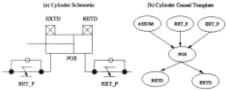
Figure 1 shows an example of a basic template in the industrial automation domain. The figure depicts the schematic and the dag representation of the template's structure for a basic component of type cylinder. A cylinder has two inputs (root nodes) corresponding to the extend and retract pressures: EXT_P and RET_P. There is one assumption variable, ASSUM (also a root node), which represents the mode of operation of the cylinder. The cylinder's piston rod position, POS causally depends on the input pressures and the assumption. The cylinder has two outputs (the leaf nodes), which are the extended EXTD and retracted RETD positions of the pis ton. Table 1 shows the tuples in the struc relation for cylinder. The values and the costs for the various domain indexes are given in the dam table shown in Fig ure 2. Table 3 shows a partial set of tuples for cylinder in the june relation. The first tuple says that if the cylin der is ak and both pressure inputs are aft then the piston position is neutral.
3 Model Specification Language
SML specification of models is based on the concept of structured template. Structured templates represent components that are composed of basic components. Examples of decomposable components in the industrial automation domain are work cells, fixtures, clamps, pins and dumps. We start by defining a structured template, then formalize the specification language and give an ex ample.
| SID | Comp_ Type | Assum_ Dom | In_ Varl | In_ Dom1 | In_ Var2 | In_ .~Iii | Out_ Var | Out_ Dom |
|---|---|---|---|---|---|---|---|---|
| 11 | Cylinder | 4 | ExLP | 1 | Ret_P | ~'· | Pos | 8 |
| 12 | Cylinder | Pos | 8 | Retd | 1 | |||
| 13 | Cylinder | Pos | 8 | Extd | 1 |
| Do miD | Vall | Val2 | Val3 | Costl | Cost2 | Cost3 |
|---|---|---|---|---|---|---|
| 1 4 8 | on ok extd | off stuck_extd retd | stuck_retd neut | 0 | 1 | 1 |
| SID | Assum | In_ Vall | In_ Val2 | Out_ Val |
|---|---|---|---|---|
| 11 11 11 11 13 13 13 | ok ok ok ok | off off on ·On extd neut retd | off on off on | neut retd extd neut on off off |
3.1 Structured Template
A structured template is specified by the basic templates of its sub-components and by the connections between those sub-components. Formally, a structured template composed of m basic templates can be specified as a pair: (S, C). S is an ordered tuple of the families of the m basic templates,
Cis a set of pairs representing the structural connections between the basic templates:
Each element in C is a connection from a node X; which is the child in some family (X;,pa(X;)) to a parent node Xk; in another family (Xj , pa(Xj)) inS such that i pre cedes j.
3.2 Specification Language
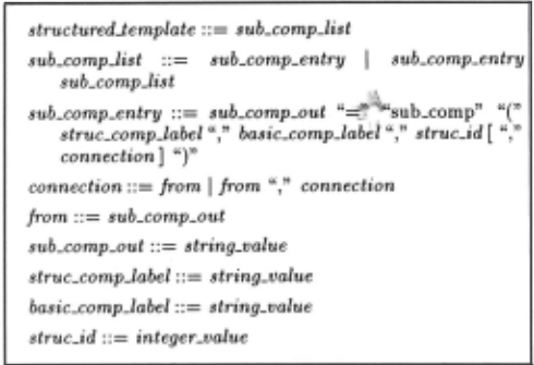
Figure 2 gives the grammar of SML model specifica tion language in EBNF (Extended Bacchus Naur Form) . Terminals are enclosed in double quotes, non-terminals are in italic, anything between square brackets are op tional. The grammar says that a structured compo nent is specified by one or more sub-components. Each
\
....
sub-component is specified by the function, sub_comp. The parameters of that function are: the structured component label, struc_comp_label; the basic compo nent label, basic_comp_/abel; the basic template struc ture id, struc_id; and the connections from other sub components. A connection consists of one or more refer ences from the outputs of parent sub-components. The sub_comp function returns a reference to the output of the defined sub-component which can then be used as the "from" attribute to another child sub-component. The connection in a sub-component definition is op tional. If included then the outputs of the parent sub components are used to replace the inputs in the defined sub-component. Else, the inputs to the defined sub component are determined by the struc relation tuple identified by struc_id. ...
Model specification is encoded in a relational table with the following scheme,
SCid denotes a structured component id and is the pri mary key. SCLabel is the structured component label. SubCompLabel is the label of a sub-component whose type is identified by the structure id, Sid. From_l , ... , From_n are foreign keys consisting of the SCid's of the parent sub-components whose outputs are connected to the respective inputs of the basic structure template identified by Sid. The function sub_comp in the SML specification has the side effect of adding a tuple repre senting the sub-component entry to the spec table. The function then returns the SCid of that tuple which can be used to encode the "From" connections as explained earlier.
3.3 Example
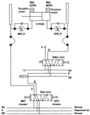
Figure 3 shows the pneumatic circuit for an industrial clamp. The function of a clamp is to hold a machine part in place on a fixture during operation on the part , e.g., a robot welding operation. The clamp has two land mark positions; namely the extended and retracted po sitions. The extended (retracted) position is produced by the control valves that connect the extend (retract) port of the cylinder to pressurized air and the retract (extend) port to the exhaust. The circuit shows two pneumatic valves connected in series. The main valve has two solenoid actuators: one for extend and the other for retract. The safety valve is a spring-return valve with only one actuator for extend. For the clamp to extend (retract), the extend actuators of both valves must be on (off) and the retract actuator of the main valve must be off (on). The extend and retract position of the clamp is sensed by proximity switches that sense the piston rod at the extended and retracted positions.
Figure 4 shows the structured template specification of a clamp set. The subcomponents of a clamp set in clude power, air, actuators, valves, cylinders and prox imity switches. Each clamp in the set is associated with a cylinder and all cylinders are actuated by the same valves. The specification is stated as an SQL procedure whose parameters are the clamp set label , Comp , and a variant array of cylinder labels. Each sub-component en try in the specification references a structure id, SID. For example the first sub-component, Power, has SID= 15, which references a basic component of type power in the struc table. Naturally, the SID values are implementa tion dependent . The next subcomponent entries are: air, the extend and retract actuators of the main valve, and the extend actuator for the safety valve. Note that those components have no from arguments which means that their inputs are exogenous variables coming from outside the clamp set. The next three subcomponent entries specify the main valve and the next two specify the safety valve. The main valve position, Vlvl_Pos , has two inputs coming from the main extend and retract ac tuators. The main valve pressure lines A and B both take input from the the main valve position. The next two entries for the safety valve are similar. The equation for the safety valve B output Vlv2_B takes an input from the main valve B output VlvLB, which implies in-series connection as indicated by the schematic in Figure 3. The "for" loop in the procedure creates for each element in the cylinders list five subcomponent entries: Three en tries for the cylinder and two for the cylinder-extended and retracted proximity switches. The air inputs to each cylinder come from the main valve A line and the safety valve B line as in the schematic in Figure 3.
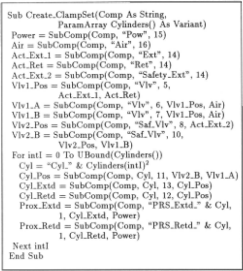
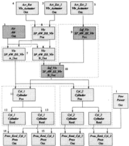
The subcomponent entries in the specification are or dered such that all connections to the inputs of a sub component come from the outputs of sub-components that are earlier in the ordering. For example, VlvLPos has its inputs coming from the earlier sub-component outputs: AcLExLl, AcLRet. Figure 5 depicts the speci fi cation structure for a clamp set instance having 2 cylin ders: cyLl, cyL2. The figure shows the ordering of the sub-components according to the structured template specification of Figure 4. Each sub-component is rep resented as a box; the name of the sub-component is shown in italics; the type is in italics and bold; and the output is shown at the bottom of the box. The figure shows that a basic component (e.g., a cylinder) consists of multiple sub-components, which are the causal net work families .
4 Model Generation
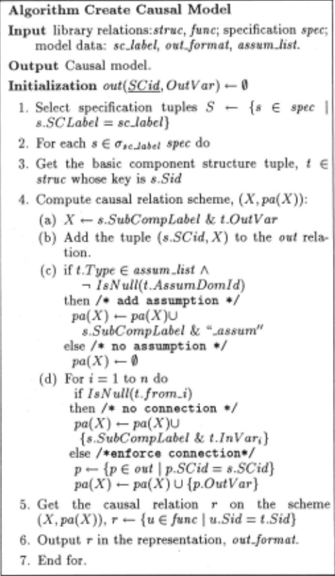
Model generation requires two information sources: (a) the template library namely the struc and June re lations, and (b) the model specification in the form of a spec relation. Causal models can be generated in some predefined format such as symbolic or relational. Rela tional format represents the causal model by a relational database where each relation corresponds to a causal net work family, (X;, pa( X;)). The name of the relation is the child variable, X;, and the attributes of the rela tim~ are the family variables, {X;} U pa(X;). The sym bolic format represents the equations for each family as a set of propositional logic sentences [Darwiche and Pearl 1994]. , The model generation algorithm is given in Figure 6. The algorithm takes as input a library of basic compo nents, specification of a structured component instance, SCLabel, an output model format, OutFormat, and an optional assumption list, AssumList. The algorithm out puts the causal model in the required format . The as sumption list consists of basic component types whose assumptions need to be included in the model. If no list is given then the model will be based on the default assumption ok for all basic component types. The algo rithm selects the specification tuples for the structured component instance (step 1) and computes for each tu ple s a causal relation r which is then output in the assigned format (steps 2-6). Step 3 selects the structure template tuple t E struc having same structure id, Sid as tuple s. Step 4 determines the scheme for the causal relation. The step prefixes the sub-component label to the assumption, input and output variables. It caches the name of the output variable in the temporary out table. If there are connections then the input variables are replaced by the proper connections from the out ta ble. An assumption is included if the structure templates mentions an assumption and the sub-component type is a member of AssumList. Step 5 populates the causal relation w.ith t~e function template tuples having same structure 1d, Std as tuple t. The time and space complexity of the algorithm is O(n·k ), where n is the number of sub-components and k is the maximum number of tu ples in the functional relation of the causal families .
5 Discussion and Related Work
The present automated modeling approach has been im plemented using the structured query language (SQL) and a relational database environment. The approach is used to model the clamping fixtures in a real-life robot welding workcell. The fixtures consist of multiple sets of pins, dumps, locators, and clamps having pneumatic cir cuits similar to the one in Figure 3. One feature of our modeling approach is the explicit representation of as sumption attributes. This is essential for building mod els for diagnosis [El Fattah and Dechter, 1995]. The models are used to generate model-based diagnostic code to run on the programmable logic controller that controls the work cell lProvan et a/., 1998].
Previous work [Falkenhainer, 1991] proposed composi tional modeling, a framework for constructing adequate device models from a model fragment library which ex plicitly represents modeling assumptions. The frame work takes a domain theory, a structural description of a specific system, and a query about the system's behav ior and searches the space of possible models to compose the right model for the query. Recent work on causal explanation [Nayak, 1994] proposed the notion of causal approximation and showed that compositional model ing becomes tractable when all model fragment approx imations are causal approximations. Our approach does not represent modeling assumptions and each compo nent type is represented by exactly one model. This is not an inherent limitation in our approach and we plan to extend it by: (1) including modeling assumptions in the relational schema of the fragments , (2) incorporat ing compositional modeling constraints in the library in the form of SQL stored procedures. We can assign costs to various model fragments and modify our model con struction algorithm to compose minimum cost models.
Specifying the model template library as a relational database enhances the maintenance and reconfiguration of models. The database encoding enables adaptability and scalability to new and unforeseen requirements and applications. New fields and record types can be added to the library database without affecting current auto mated modeling programs. Our database approach en hances the reliability of the modeling data through the use of proper integrity constraints, e.g., key integrity, domain integrity and referential integrity.
The focus of previous work on automated modeling in bayesian networks has been primarily on the represen tation of probabilistic knowledge as network fragments and not on algorithms for constructing models from the knowledge base [Laskey and Mahoney, 1997] . A main contribution of our approach is the description of an efficient algorithm for automated generation of causal models. The algorithm can be stated declaratively in SQL, which enhances the expressiveness and naturalness of model-building operations. The ubiquity of database environments and industry standard SQL servers are two factors in favor of our database approach to automated modeling.
An advantage of our approach is the ability to describe models with a generalized number of sub-components. For example, our clamp set model includes a variable number of clamps in the template which can then be instantiated for generating specific models. See Fig ure 4. The OOBN language [Koller and Pfeffer, 1997] cannot represent models with varying number . For ex ample, the OOBN approach cannot represent a model of a car accident with a variable number of passengers ; instead it will represent a distinct model for each pos sible number of passengers [Koller and Pfeffer , 1997]. Also, the OOBN language is poorly equipped to rep resent global constraints on the sub-components. For example, it cannot represent that a car contains three passengers, at least one of whom is a child [Koller and Pfeffer, 1997]. Our relational approach can express such global constraints as global consistency queries. The key to the expressive power of our approach is that struc tured model templates are represented as parameterized relational queries that can be instantiated to generate specific model instances.
The present modeling framework can be extended to represent temporal causal networks [El Fattah and Provan, 1997]. This can be done by classifying causal relations in two classes: instantaneous and delayed and by including temporal data for delayed relations. The value of the output of a causal relation at any time t is determined by the values of the inputs at t if the relation is instantaneous and at t - d if the relation is delayed, where d > 0 is the time delay.
Our structured template specification requires a causal ordering of the subcomponents, similar to those used to describe the operation of physical devices [Kuipers, 1984; Iwasaki and Simon, 1986; de Kleer and Brown, 1986] . Previous work on bond graphs has also developed meth ods for causal ordering from a compositional modeling perspective [El Fattah, 1996]. Causal ordering is orthog onal to our modeling approach. We assume that all basic components consist of causal constraints [Dechter and Pearl, 1991] with pre-defined input-output directional ity. The causal structure of our structured components is determined by the directed connections between its subcomponenets. If the connections and the basic con straints are non-directional then a causal ordering algo rithm can be employed and the directional constraints are then cached in our database library.
6 Conclusions
The paper presents a structured modeling language for automated modeling in causal networks. The language provides a formal method for specification of models based on a library of basic components. The library is represented by two relations: strue and June. The strue relation describes the templates for the structure of basic components, which determines the causal rela tion scheme and the associated causal network families. The June relation contains the value tuples for the causal relations of the basic components. The specification of models is done by instantiating structured component templates defined in SML. The information required for instantiating the templates can be acquired automati cally from the schematic representation, e.g. the wiring diagrams, of the modeled system. The modeling knowl edge is captured and maintained in the basic component library, which is then reused to generate causal mod els. The paper describes an efficient algorithm for the automated generation of causal models from specifica tion. The approach has been implemented and success fully used to model an automated work-cell in a real-life digital manufacturing application.
@inproceedings{ijcai1999p158,
  title     = {Structured Modeling Language for Automated Modeling in Causal Networks},
  author    = {Fattah, Yousri El},
  booktitle = {Proceedings of the Sixteenth International Joint Conference on
               Artificial Intelligence, {IJCAI-99}},
  publisher = {International Joint Conferences on Artificial Intelligence},
  editor    = {Thomas Dean},
  pages     = {1108--1116},
  year      = {1999},
  note      = {Qualitative Reasoning and Diagnosis},
  url       = {https://ijcai.org/proceedings/1999/158},
}
TY - CPAPER TI - Structured Modeling Language for Automated Modeling in Causal Networks AU - Fattah, Yousri El T2 - Proceedings of the Sixteenth International Joint Conference on Artificial Intelligence, IJCAI-99 PB - International Joint Conferences on Artificial Intelligence PY - 1999 SP - 1108 EP - 1116 UR - https://ijcai.org/proceedings/1999/158 ER -Copied
Machine-readable versions of this paper, for tools and AI agents:





