
Qualitative and Quantitative Representations of Locomotion and their Application in Robot Navigation
Proceedings of the Sixteenth International Joint Conference on Artificial Intelligence. Qualitative Reasoning and Diagnosis. Pages 1067-1072.
© 1999 International Joint Conferences on Artificial Intelligence
Abstract
Qualitative and quantitative representations of space in general and motion in particular have their typical fields of app li cation which are unified in an autonomously moving robot interacting with human beings. Therefore it is necessary to make some considerations on both approaches when dealing with such a robot. This paper presents quantitative and qualitative representations of locomotion and algorithms to deal with them. This work was applied to the navigation of a semi-autonomous wheelchair along routes in networks of corridors.
- [Clementini et al., 1997] Eliseo Clementini, Paolino Di Felice, and Daniel Hernandez. Qualitative rep- resentation of positional information. Artificial Intelligence, 95(2):317-356, 1997.
- [Krieg-Briickner et al., 1998] B. Krieg-Briickner, Th. Rofer, H.-0. Carmesin, and R. Miiller. A taxonomy of spatial knowledge and its application to the Bremen Autonomous Wheelchair. In Ch. Freksa, Ch.
- Habel, and K. F. Wender, editors, Spatial Cognition, volume 1404 of Lecture Notes in Artificial Intelligence, pages 373-397. Springer, 1998.
- [Musto et al., 1998] A. Musto, K. Stein, A. Eisenkolb, K. Schill, and W. Brauer. Generalization, segmenta- tion and classification of qualitative motion data. In Henri Prade, editor, Proceedings of the 13th European Conference on Artificial Intelligence (ECAI-98).
- [Tversky, 1993] Barbara Tversky. Cognitive maps, cog- nitive collages, and spatial mental models. In An- drew U. Frank and Irene Campari, editors, Spa- tial Information Theory. A Theoretical Basis for GIS. European Conference, COSIT'93, volume 716 of Lecture Notes in Computer Science, pages 14- 24, Berlin,Heidelberg,New York, September 1993. Springer.
References were extracted automatically from the PDF and may contain errors.
Full text extracted automatically from the PDF; figures, tables and equations may differ. The PDF is the version of record.
1 Introduction
Qualitative and numeric representations have both their pros and cons and most of them apply to the field of motion representation, too. Since qualitative representa tions (QR) are coarse, they focus on the items where the representanda differ, what leads to very compact descrip tions. Furthermore, a QR can reflect and compensate vague data better than a quantitative one, which often computes at an unnecessary level of accuracy. L(lSt, qual itative representations are good where human-machine interaction takes place. Humans think mostly in qual itative categories like left/right and close/far (see e. g. [Tversky, 1993]), and not numeric ones like 78° and 135 em, and therefore it is better to make the computer un derstand these categories than to force the human to communicate in an unnatural manner.
On the other hand, numeric representations are more precise and often easier to handle by a machine. There fore, in an autonomously moving robot which has to un derstand user commands like the Bremen Autonomous Wheelchair, both numeric and qualitative representa tions of rriotion data should be available.
The Bremen Autonomous Wheelchair supports per sons with severe impairments, e. g. blind people, in driv ing through their apartment or through the office build ing at their place of work. Among other applications, one level of support of the assistive system is the au tonomous driving along pre-taught routes, i.e. a simple form of navigation. Navigation requires a representation
Andreas Eisenkolb
Institut f. med. Psychologie LMU Mi.inchen Goethestr. 31 80336 Mi.inchen, Germany
Thomas Rofer
Bremer Inst. f. Sichere Systeme Universitiit Bremen Postfach 330440 28334 Bremen, Germany
of the environment, i.e. spatial knowledge. An informa tion that can easily be acquired is the motion data of the wheelchair. These motion tracks can be simplified (generalized), and can either be represented in a numeric or qualitative way.
So, this paper deals with both numeric and qualitative representations of motion data. First, the navigation approach is presented that is based on the generalization of motion tracks. Then, qualitative representations of locomotion are discussed that will be the basis for the human interface of the wheelchair in future.
2 Locomotion in Robot Navigation
Wheelchairs are normally installed by a salesperson of a medical shop or a wheelchair mechanic. As maps including all furniture , etc.-are too complex to be ac quired by the service persons, the idea of "teaching" was selected as an appropriate method to impart the spatial knowledge required for navigation to the au tonomous system. As was described by Krieg-Briickner et al. [1998], routes can be represented as sequences of basic behaviors and so-called routemarks that trigger the switching between the behaviors. These combinations should be learned during teaching drives-one for each route-when the wheelchair is delivered. After that , the wheelchair is able to t ravel the routes autonomously. Krieg-Briickner et al. used a camera to detect artificial routemarks. However, this approach had two drawbacks: on the one hand, the environment has to be prepared to use this method, and on the other hand, the wheel chair has to be equipped with a camera on a turntable, which is an expensive solution. Therefore, a more cost effective approach has been chosen to find points of ref erence along the routes that only uses the sensory equip ment that is already required for the basic functionality of the wheelchair, e. g. for collision avoidance: the analy sis of the wheelchair's course of motion when performing distance-driven basic behaviors.
2.1 The Bremen Autonomous Wheelchair
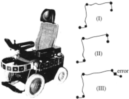
The basis for the Bremen Autonomous Wheelchair "Rol land" is a commercial power wheelchair manufactured by the German company Meyra (cf. Figure 1). It is a non holonomic vehicle that is driven by its front wheels and steered by its back wheels. It is equipped with 27 Po laroid sonar sensors mounted around the system and a PC placed behind the seat. In addition, the wheelchair is able to measure its actual speed and steering radius. Thus it can perform dead reckoning.
2.2 Motion Tracks of a Mobile System
The basic idea of the route navigation approach pre sented here is the following: when the wheelchair drives using basic behaviors such as wall-following, its move ments reflect the structure of the environment. The dead reckoning system of the wheelchair can record these movements. The resulting motion tracks can be em ployed to generate representations of the routes the sys tem has followed. If the system drives along a route a second time, its dead reckoning system will produce a very similar track. In order to be able to use such repre sentations for navigation, a method has to be found to match different tracks to perform, e. g., a self-localization along the route.
In comparison to methods that try to generate map like representations of the environment, e. g., with the help of distance sensors, the major advantage of motion tracks is their continuity. This is a result of the con tinuous motion of the wheelchair. The noise in the sen sor readings is considerably reduced by the inertia of the mobile system because the distance measurements of the sensors influence the route representation only indirectly via the basic behaviors.
2.3 Navigation Approach
In the navigation approach presented here, the wheel chair is controlled along a route by switching be tween the basic behaviors wall-following, i. e. follow ing the left or right wall while driving either in for ward or backward direction, corridor-following (for wards/backwards), turning-into-door (left/right door), and stop. The system records its dead reckoning posi tions as well as the changes of the behaviors. As the odometry data can consist of many measurements, it is generalized to generate a compact representation of the route that is stored. This information is used as a refer ence for autonomous drives along this route. Based on the assumption that navigation in buildings is essentially a combination of following corridors and turning at cor ners, a representation has been chosen in which routes consist of straight lines that cross under certain angles. Therefore, a route description is a sequence of distances and angles, e. g. "800 em, 89°, 345 em, -83°, 566 em" .
In an autonomous replay, the dead reckoning data is recorded, too. It is generalized the same way as during the teaching drive, and then the two representations are matched. The description stored always represents the complete route whereas the current motion track only stands for the part of the route traveled so far. There fore, the current description can only be matched to the beginning of the stored one. The segment in the stored representation that is matched with the last segment of the current track is the current segment. Together with the length of the last segment in the current track, i.e. the distance to the last corner, this defines the wheel chair's current position with respect to the reference rep resentation. This position can be used to switch between the basic behaviors at appropriate locations, and thus enables the system to repeat the route stored.
By the way, this approach allows a second application: During the matching of the two generalizations, it can be determined whether they represent the same route or not. Thus it can be noticed when the wheelchair has lost its way, because, e. g., a behavior was performed erroneously. This is depicted in Figure 1 that shows three route descriptions: the first one was learned ( cf. Figure 1 I) , the second is a correct repetition of the first one ( cf. Figure 1 II), and the third is an erroneous replay (cf. Figure 1 III). In case of the latter, the mistake was detected shortly after the erroneous behavior occurred, i.e. the wheelchair missed a door because it was closed.
3 Incremental Numeric Generalization
To fulfill the requirements of the navigation task, a method was developed to generalize the numeric motion data incrementally, i.e. on the fly when the autonomous system drives. As we shall see later, this incremental generalization is also useful for the generation of quali tative route descriptions.
The basic idea of generalizing a given track T is to find a simpler track U representing the general shape of T - i.e. the important global information-and suppress ing small zigzags and deviations. A simple approach to generalize T is to create a polygon track U differing less than a distance c from T (c requirement). In case of the wheelchair application, c is not a predefined constant, because the generalization is used to unveil the struc ture of the environment. Therefore, each segment in the generalization should correspond to a corridor in real ity. The wheelchair's freedom of movement is limited by the walls of the corridors it is following. Therefore, it is reasonable to use the widths of the passages the system is traveling as €. The widths of the corridors are deter mined robustly by preprocessing the sonar measurement with a histogram approach.
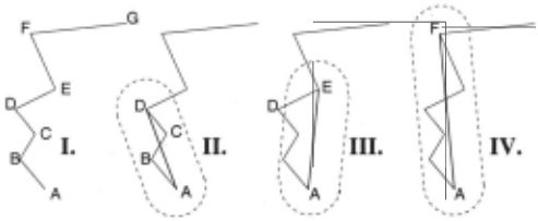
An incremental algorithm based on this idea is illus trated in Figure 2: starting from A, the algorithm follows the polygon track, tries to build a straight line segment from the actual starting point to the current point and tests whether each point between the starting point and the current point is within the €-surrounding of the gen eralized line segment. In Figure 2 II, the distance of the points B and C to (AD] is tested to be less than c. So, the line (AD] qualifies as generalization of the polygon track between A and D, and the algorithm tries to pro ceed by taking the next point E as new end point for the generalized line segment. In this case, the point D is outside the €-surrounding of the generalized line segment (cf. Figure 2 III). Now the algorithm tests whether there could be a further reference line closer to this point when the polygon track proceeds. This is the case with line (AF]. The algorithm only takes a point as an endpoint of a generalized line segment when no further reference line could fulfill the c requirement, or if the input stream is closed. Then the last correct reference line segment is taken and its endpoint is used as the end of the first part of the generalized track, and simultaneously this point is the start for the next iteration.
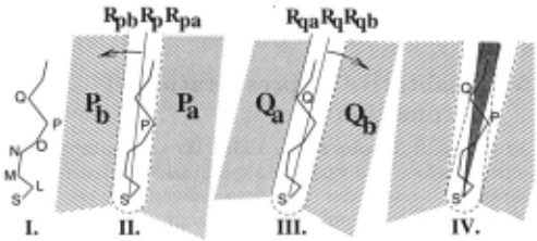
Figure 3 visualizes the algorithm that tests whether the construction of a further reference line fulfilling the €-requirement is possible: the first end point of the ref erence line segment is the starting point 5 and the line can rotate around this point. Any point further than c away from 5 limits the angle of rotation for any longer reference line segment starting with S: for example, since 5 and L are not farther than c away from each other, any reference line would fulfill the requirement. The addition of point N to the track limits the possible directions of rotation: the line could not go backwards from S, since 5 and N are farther than c away from each other.
Continuing with the example, in Figure 3 II, P pre vents any further rotation of the reference line shown to the left , in Figure 3 III Q prevents a rotation to the right. Therefore, for any point in Pb or Qb it is impossible to find a reference line (Rp, Rpa, Rpb, Rq, Rqa , Rqb are easy to compute).
The general algorithm works as follows: Starting with 5 = X1 any new point Xn is tested:
- It is either in Pb or Qb: the end of a segment has been passed. The last line (X1 , Xk], (k < n) fulfilling the €-requirement is the generalization of the first segment and 5 = xk+l is new starting point.
- It is in P a or Qa: Xn is a new border point and Rp, Rpa, Rpb (or Rq , Rqa, Rqb) are recomputed.
However, although the resulting partitioning satisfies the €-requirement, it seems rather random for the robot navigation tasks, since it does not take the environment into account. Xk is only an arbitrary point behind the corner at the end of the segment, and its selection is influenced by the fine structure of the movements in the segment. Instead, the corner is a stable feature, and therefore it has been chosen as end point for segments. The basic idea for determining the position of the corner is that two successive line segments build two sides of a triangle. Seen from both end positions of the two sides, the sum of the lengths of both sides should be maximal at the corner. However, this approach only works robustly if both sides of the triangle have approximately the same length. Therefore, the second segment is lengthened by the distance between xl and xk towards the direction of movement at Xk . As a result, the corner is determined and serves as end point of the first segment as well as starting point of the second one.
The resulting, smooth motion track is a polygon track consisting only of the segments 51 ... Sn. An implicit assumption in the navigation approach presented in sec tion 2.3 is that similar motion tracks are generalized to similar route representations. However, there are two cases in which this conjecture is violated by the approach presented:
- If there are long parts with a slight curvature in a motion track, either because a corridor has this shape, or- more likely-because of odometry drift, its generalization may be arbitrary. Small variations in the wheelchair's course may generate very differ ent segments. However, the angles between such arbitrarily separated segments are always small.
- If a corridor's width is similar to its length, it may be generalized to a separate segment in one track ( cf.
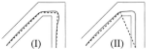
Figure 4: Two motion tracks and their generalizations
Whereas the first problem could be handled during generalization process by combining neighboring seg ments connected with small angles, the second problem cannot be eliminated during the generalization. There fore, both problems are only just taken into account during the matching process that can deal with both of them.
4 Matching Generalized Motion Tracks
Two generalized tracks are matched by running through both of them segment by segment. On the one hand, this allows to determine corresponding segments, on the other hand, it can be checked whether both tracks de scribe the same route. To perform the latter, the seg ments of the tracks as well as the angles between them are compared. If they are not similar enough, the tracks are incompatible, and therefore it is assumed that they do not describe the same route, i.e., the wheelchair has moved along a different trajectory.
As has been discussed in section 2.3, the current track will normally be shorter than the reference track. There fore, the matching of the two tracks is not a symmetric process because one of the two route representations is allowed to be shorter than the other one. Hence, the matching function tests whether the current track is less or equal than the reference track, and if this is the cas~, it determines the position in the reference track where the current track ends, i.e. it calculates the correspond ing segment in the reference track and uses the length of the last segment in the current track as metrical offset from the beginning of the segment.
For each pair of segments from both tracks, it is first checked whether their lengths are similar. They are as sumed to be compatible if their difference is not greater than the sum of the four following values 1 :
- The width of the previous segment if the current segment is not the first one.
- The width of the successive segment if the current segment is not the last one.
- A base tolerance that should be larger than the dis tance between two neighboring positions in the orig inal tracks. In the work presented here, it was set to 50 em.
1 The only exception is the last segment of the current motion track that is allowed to be arbitrarily short because it was not recorded completely so far .
- A factor that models odometry errors depending on the distance traveled. The wheelchair's odometry is quite reliable in measuring lengths of straight lines. So, the tolerance can be small, i.e. 2%.
If the difference is larger, the tracks seem to be incom patible. How~ver, as has been discussed in the previous section, it is possible that the segment in the current track is too long because it is the counterpart for two segments in the reference track. Therefore if either the current segment in the reference track or its successor is short, or the angle between both segments is small, the two segments are joined and the matching is retried. The opposite case is given if the actual segment in the current track is significantly shorter than the one in the reference track, and it is not the last segment. Then, it is tried to overcome the mismatch by joining two adja cent segments in the current track. If they cannot be joined because the segments are too long or the last seg ment in the reference track has been reached but there are still further segments in the current track, the two representations are assumed to be incompatible. Oth erwise, if the actual segment in the current track is the last one, the matching was successful, and the corre sponding segment in the reference track has been found. Together with the length of the last segment in the cur rent motion track, this can be used as one-dimensional self-localization along the route, and thus it can trigger the activation of the basic behaviors.
If the last segment in the current motion track has not been reached, the angles are compared. This compari son is performed in a qualitative way because the angles may differ heavily if, e.g., parts of the route are general ized with a different number of segments. The angles are mapped to the four qualitative categories "left", "right", "forwards", and "backwards" that describe overlapping angular ranges. Two angles are assumed to be compati ble if they both share at least one qualitative category.
left = ]0 ... 180°[ right= ]-180° ... 0[ forwards= [-20° ... 20°] backwards = [ -180° ... -160°, 160° ... 180°]5 Qualitative Representation of Locomotion
As shown in [Musto et al., 1998], the computations de scribed before also work on a qualitative representation. However, because the basic data delivered by the wheel chair is numeric, computation is kept numeric and the main purpose of the qualitative representation here is human computer interaction. The logged locomotion data can be used to generate a qualitative representa tion of the course of motion that can be used for natural language output, e. g. to give a blind person some feed back on what the wheelchair is doing to reassure him that he is still on the right way, or to help him to an ticipate coming actions of the wheelchair. This sort of feedback can consist in directional information ("Going to the left instead of forward is o.k. here because of ob stacle avoidance"), in distance information ("This route segment is very long") , or in velocity information ("Driv ing this route segment so fast is ok, since there is plenty of space"). To give such a feedback, qualitative repre sentations of the logged reference track and the actual track are neceessary.
Since qualitative computation is possible, the wheel chair is able to deal with this qualitative data as input , too. The considerations on the qualitative representa tion can therefore serve as basis for a natural language input, e. g. to allow intervention of a user who is able to anticipate a possible error of the wheelchair in order to avoid it.
5.1 Motion Representation through Qualitative Distances and Directions
As we have pointed out above, for our task it suffices to represent only distance and direction of a motion event. To this end we use qualitative categories like "left", "right", "far", "close", etc. Then, a course of motion can be represented by a sequence of qualitative motion vectors (QMVs), i.e. vectors that describe the motion of an object from position n - 1, measured at measurement point n - 1, to position n, measured at measurement point n, where the vector components are some qualitative descriptions of, e. g., direction, distance, and speed of the object when moving from point n- 1 to point n. Assuming a fixed scan rate, speed can sim ply be computed from the distance covered in one scan cycle.

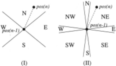
To represent a course of motion through qualitative di rections and distances, we have to discretize space some how into areas to which these categories apply. Figures 5 and 6 are examples of possible discretizations.
5.2 QMVs in Egocentric and Allocentric Frames of Reference
When measuring locomotion we have to distinguish be tween two cases: do we have some external system of coordinates to measure our motion data (e. g. in a GPS track), or not (e. g. when using odometry data in robotics)? In the first case, we measure the data in an allocentric frame of reference (FoR), in the second case we determine it in an egocentric one.
In an allocentric FoR in measurement, the approach by Musto et al. [1998) works out. There, a course of motion is measured with a fixed scan rate and mapped into qualitative intervals in each scan cycle. Space is discretized in the domain of distance and direction like in Figures 5 and 6 I, following the suggestions of Clementini et al. [1997). So, a course of motion is represented as sequence of qualitative motion vectors, e. g.
<close east>5 <close north>2 <close west>3 <close south> 1 <medium-dist south> 1 <medium-dist east> 1 .The indices indicate the number of scan cycles without a change in distance and direction.
If the course of motion is measured in an allocentric FoR like here, switches between allocentric and egocen tric FoR in the domain of direction are possible without a loss of information. A representation in the egocentric FoR of the QMV sequence above reads:
<close forward>5 <close left>2 <close left>3 <close left> 1 <medium-dist forward> 1 <medium-dist left> 1 .Unfortunately, in the domain of locomotion this ap proach isn't suitable: Since there is no external, fixed, and relatively unchanging FoR when measuring locomo tion, the direction gridlock has to be realigned in each scan cycle, depending on the new intrinsic orientation of the person or robot moving. Therefore, small changes in the direction in each scan cycle might be never noticed, but may accumulate to a rather big change in many scan cycles ( cf. Figure 7) . The only directional changes no ticed would be very sharp ones in a single scan cycle. This leads to the dissatisfactory situation that the rep resentation of the spatial path of a course of motion at a given scan rate depends greatly on the speed of the moving object.
The reverse paradigm does better in this context: measuring changes in direction not in every scan cycle, but only after a certain distance was covered, makes sure that the resulting representation does not depend on the speed of the motion.
Then, following Musto et al. [1998), we can represent locomotion as a sequence of egoQMVs, measured and represented in the egocentric FoR. An egoQMV con sists of the components direction D, e. g. {forward, backward, left, right}, and number of time cycles t needed to cover the fixed distance. A counter indicates the number of measurement cycles without a change in direction and speed 2 : <t , D> i. Thus a course of motion is represented as a sequence of egoQMVs:
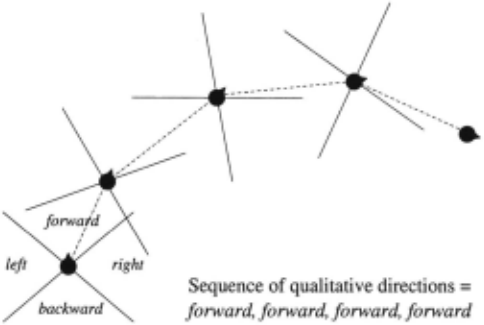
As a result, we can encode distance (represented by the counter) and speed (represented by the timet) somehow more qualitatively, too, and get the following represen tation3:
<close forward fast> <close right medium-speed> <close backward slow> <very-close left medium-speed>.
5.3 Discussion
As we could see from the considerations above, mapping distance and direction directly into qualitative intervals in each scan- or measurement cycle maybe necessary for some applications like giving immediate feedback on the robot's actions, but has the disadvantage that much in formation is lost, and it is error-prone, e. g. if the mea surement cycle is not well-chosen.
Therefore we should use the incremental generaliza tion algorithm as presented in section 3 whenever pos sible to smooth away irrelevant deviations. The result ing numeric representation can easily be converted into a qualitative one by mapping the remaining changes in direction and speed into qualitative intervals after each segment has been generalized. This can also be done with the recorded reference track that can be used in combination with the actual track to give the user an ticipation information.
The QMV representation gives qualitative information about direction, distance, and speed of the motion per formed, and so has all relevant motion data handy in a form that is well understandable for humans.
2 Since we measure after a fixed distance, t is equivalent to speed: the larger the number, the slower the robot is moving.
3 The representation is equivalent to the one we get from the allocentric measurement and the conversion into the ego centric FoR if we also express speed qualitatively.
However, the qualitative representation can not only be used for user interaction, but also reflects the struc ture of the environment. Since corners and turns in the spatial path are not only landmarks, but also de fine spatial relations between other landmarks like doors or corridors crossing, this information can be incorpo rated into a weakly constrained net of landmarks and spatial relations between them, where constraints can be propagated and used to build up a route map.
6 Conclusion and Outlook
This paper has presented quantitative and qualitative representations of locomotion in the robotics context. The work was applied to the problem of navigation along routes in networks of corridors. Tests with routes longer than 100m proved that the generalization of motion data is an appropriate means to unveil the structure of the environment the data was recorded in. Thus, it is an easy but reliable technique for navigation. The considerations on the qualitative representations will be the basis for the human interface of the wheelchair in future.
Furthermore, a method that automatically combines representations of different routes to a topological net work, the so-called route map, will be developed. This will ease acquiring the spatial knowledge to freely navi gate in complete buildings.
@inproceedings{ijcai1999p152,
  title     = {Qualitative and Quantitative Representations of Locomotion and their Application in Robot Navigation},
  author    = {Musto, Alexandra and Stein, Klaus and Eisenkolb, Andreas and Röfer, Thomas},
  booktitle = {Proceedings of the Sixteenth International Joint Conference on
               Artificial Intelligence, {IJCAI-99}},
  publisher = {International Joint Conferences on Artificial Intelligence},
  editor    = {Thomas Dean},
  pages     = {1067--1072},
  year      = {1999},
  note      = {Qualitative Reasoning and Diagnosis},
  url       = {https://ijcai.org/proceedings/1999/152},
}
TY - CPAPER TI - Qualitative and Quantitative Representations of Locomotion and their Application in Robot Navigation AU - Musto, Alexandra AU - Stein, Klaus AU - Eisenkolb, Andreas AU - Röfer, Thomas T2 - Proceedings of the Sixteenth International Joint Conference on Artificial Intelligence, IJCAI-99 PB - International Joint Conferences on Artificial Intelligence PY - 1999 SP - 1067 EP - 1072 UR - https://ijcai.org/proceedings/1999/152 ER -Copied
Machine-readable versions of this paper, for tools and AI agents:





