
FBRL: A Function and Behavior Representation Language
Proceedings of the Fourteenth International Joint Conference on Artificial Intelligence. Qualitative Reasoning and Diagnosis. Pages 1830-1835.
© 1995 International Joint Conferences on Artificial Intelligence
Abstract
This paper proposes FBRL, a language for representing function and behavior with the primitives we identified and discusses its application to explanation generation. FBRL explicitly represents model of each component in a system in terms of two elements. One is a necessary and sufficient information for simulation of the component which we call behavior . The other is the interpretation of the behavior under a desirable state which the component is expected to achieve, which we call function. By identifying primitives necessary for the interpretation of the behavior in various domains, we can capture what function is and represent it by selection and combination of them. We also investigate the relation between function and behavior based on the primitives of FBRL. As FBRL can represent concepts at various levels of abstraction, it contributes to explanation generation by providing information for mapping behavior of a component to a term which represents its function.
- [Abu-Hanna et a/., 1991] A. Abu-Hanna, R. Benjamins, and W. J answeijer. Device understanding and modelilng for diagnosis. IEEE Exp ert, pages 26-32, April 1991.
- [Chandrasekaran et al., 1993] B.Chandrasekaran, A.K.Goel, and Y.lwasaki. Functional representation as design ratio- nale. COMPUTER, pages 48-56, January 1993.
- [de Kleer and J.S.Brown, 1984] J de Kleer and J.S.Brown. A qualitative physics based on confluences. Artificial Int elli• gence, 24:7-83, 1984.
- [de Kleer, 1984] J de Kleer. How circuits work. Artificial Int ellig ence, 24:205-280, 1984.
- [Gruber and Gautier, 1993] Thomas R. Gruber and Patrice 0. Gautier. Machine-generated explanations of engineer- ing models:a compositional modeling approach. In Pro- ceedings of the IJCAI, pages 1502-1508, 1993. IJCAI
- [Iwasaki et al., 1993] Y. Iwasaki, R. Fikes, M. Vescovi, and B. Chandrasekaran_ How things are intended to work: Capturing functional knowledge in device design. In Pro- ceedings of the IJCAI, pages 1516-1522, 1993.
- [Keuneke, 1991] A.M. Keuneke. Device representation:the significance of functional knowledge . IEEE Expert, 24:22- 25, April 1991.
- [Kitamura et a/., 1994] Y. Kitamura, M. Sasajlma, M. Ikeda, and R. Mizoguchi. Model building and qualitative reason- ing for diagnostic shell. In Proceedings of the JKJCES, pages 41-46, 1994.
- [Pegah et al., 1993] M _ P egah, J. Sticklen, and W. Bond. Functional representation and reasoning about the F / A-18 aircraft fuel system. IEEE Expert, 24:65-71 , April 1993.
- [Sasajima et a/., 1994a] M. Sasajima, Y. Kitamura, Song Yang, S. Yoshikawa, A. Endou , M. Ikeda, and R. Mi- zoguchi. Development of a system for generating explana- tions using Functional representation language FBRL. In SIG-l-9401-11{12/2) , pages 79-86. Japanese Society for Artificial Intelligence, 1994. in Japanese.
- [Sasajima et a/., 1994b] M.Sasajima, Y.Kitamura, M.Ikeda, S.Yoshikawa, A.Endou , and R .Mizoguchi. An investiga- tion on domain ontology to represent functional models. In Proceedings of th e Eighth International Workshop on Qualitative Reasoning about Physical Systems, pages 223- 233, 1994.
- [Sembugamoorthy and Chandrasekaran, 1986] V Sembug- amoorthy and B Chandrasekaran. Functional represen- tation of devices and compilation of diagnostic problem- solving systems. In J .L. Kolodner and C.K Riesbeck, ed- itors, Experience, M emory, and R easoning, pages 47-73.
- Lawrence Erlbaum Associates, Hillsdale, N.J_, 1986.
- [Stevens and Steinberg, 1981] Albert Stevens and Cindy Steinberg. A Typology of Explanations and Its Appli- cation to Intelligent Computer Aided Instruction. Re- port no.4626, Bolt Berenek and Newman Inc., 50 Moulton Street Cambridge, Massachusetts 02138, March 1981.
- [Swartout et al., 1991] W. Swartout, C. Paris, and J. Moore. Design for explainable expert systems. IEEE Exp ert, pages 58-64, June 1991.
- [van Amerongen and M .Sc. , 1972] C. van Amerongen and AMICE M.Sc. HOW THINGS WORK Volume II. Granada Publishing Limited, 1972.
- [Vescovi et al., 1993] M. Vescovi, Y Iwasaki, R Fikes, and B Chandrasekaran. CFRL:A language for specifying the causal functionality of engineered devices. In Proceedingj of th e AAAI, pages 626-633, 1993.
References were extracted automatically from the PDF and may contain errors.
Full text extracted automatically from the PDF; figures, tables and equations may differ. The PDF is the version of record.
1 Introduction
One of the main themes about model-based problem solvers is to establish a method for describing good qual itative models which are utilized for simulation of the target system, explanation generation, evaluation, diag nostic reasoning, design, etc. The concept of function and behavior play important roles in such model-based systems, because behavior is closely related to simula tion task and function to inference tasks at the concep tual level. At the same time both of the two concepts together form core of the ontology to which human users and machines commit to share understanding and repre sentation of the target models. Thus deep analysis and understanding of the behavior and function is critical in the field of model-based problem solving.
One of the easiest ways of modeling a target system is to configure predefined components. Although this approach is promising, it requires careful representation of function and behavior of each component in order to make it effective and reusable. It has been pointed out, however, that function and behavior are likely to be con fused and mixed in each other in the process of modeling each component [de Kleer and J.S.Brown, 19&4]. Since such mixing lowers the reusability of the models, a mod eling method has to separate them from each other care fully.
Some researchers have dealt with functional modeling to date. de Kleer[de Kleer, 1984] represents behavior of a component as a set of input-output relationship each of which represents causality among parameters of the component. He recognizes function of a component by selecting an input-output relationship from possible be haviors. The selection is an important element for iden tifying function of a component, but it is not sufficient. In some cases component has multiple functions while its behavior is unique. A heat exchanger is a good example. When it is built in a power plant as an evaporator, its function is "give heat energy to the water and maintain temperature of the output vapor". On the other hand, when it is built in a car as a radiator, same behavior is interpreted as "remove heat to prevent overheat" .
Chandrasekaran[Chandrasekaran et al., 1993] pro poses a framework for representing and utilizing func tional models. The framework represents a functional model of a component by combining its subcomponents' behavior or function, which in tern represents behavioral or functional role of the component in a macroscopic view. Consequently, the method allows behavioral mod els to become functional models by changing its grain SIZe.
Thus their definition of behavior and function are rel ative and does not represent an essential difference be tween them. An ideal method for functional represen tation should explicitly represent an essential difference between function and behavior. Furthermore, the mod els represented by the method should be highly reusable. Standing on these view points, those methods of func tional representation proposed to date do not satisfy our needs.
The authors recognize several viewpoints from which we can capture difference between function and behav ior. For establishing a new representation method which reflects our ideas about function and behavior, we first define both of them. Behavior representation of a com ponent is the necessary and sufficient information for simulating state change of components in a system. Parameters which represent the states of components and constraints or causal relationships among them are in cluded in the behavior representation. Next, we can recognize an intended desirable state for each of com ponents in a system. We call the state a goal. Lastly, with necessary information, we can interpret the behav ior of a component under its goal. For example, under the goal, "temperature of coolant out to the next com ponent does not exceed Tthreshold", behavior of a heat exchanger is interpreted as "to cool coolant" (to prevent overheat of next component, engine) . We call such in terpretation result as function.
Following the above discussion, we have developed a new functional representation language FBRL which has a rich vocabulary for function and behavior. The vocabulary consists of important terms for representing concepts about a portion of domain which we call do main ontology. In this sense, our work contributes to organizing domain ontology. FBRL represents a func tional model as a behavior model plus FT, where FT stands for Functional Topping, a set of information nec essary for interpretation of behavior. By collecting prim itives enough for describing behavior and FT, FBRL enables us to describe various functional models by se lecting some of the primitives and combining them.
Furthermore, using FBRL functional models, an ex pert system can generate various types of explanations in terms of function level vocabulary, which is difficult for those systems without knowledge of function. Such explanations have potential to help users understand a target system well.
This paper consists of two main parts. The first half discuss FBRL and the second half an application of FBRL to explanation generation with an example.
2 Primitives to represent functional models
To establish a framework for describing a functional model of components, we investigate several viewpoints to capture the behavior and FT, the additional informa tion to interpret the behavior. In this section, we briefly discuss the viewpoints and primitives to represent them in order.
For designing a language, discussion about its formal semantics and meaning which we want to present by the language is necessary. This paper introduces FBRL with paying attention not to its semantics but to the meaning, i.e. ontology of function and behavior. More details about the discussion are available in [Sasajima et al., 1994b].
2.1 Format to describe components
A template for describing behavior and function of a component is shown in Fig.l.
The behavior of a component is represented by rela tions among input and output objects. In the template, it is represented by first seven attributes, from Objects to QN-Relations. Other five slots represents necessary information for interpreting the behavior which we call FT.
We model function of a system as a composite of a set of sub functions of its subsystems. Whatever the grain size of the subsystem may be, decomposition of a func tion into a set of behaviors is not allowed. After the decomposition a functional model of the system is repre sented as a set of hierarchically connected components.
| Behavior: Objects: | /* Objects input to or output from the component * / |
| SubComponents: MP-Relations: | /* Names of subcomponents * / /* Relations among input materials and output products * / |
| SameClass: | /* Sameness of the class of in/out objects * / |
| InherentParams: | /* Parameters inherent in the component * / |
| Ports: | /* Connection with neighbour components * / |
| QN-Relations: | /* Quantitative relations among parameters * / |
| Functional Topping: | |
|---|---|
| Goal: | /* Goal of the component * / |
| FuncType: | /*Function type:ToMake,ToPrevent , ToControl, ToMaintain, ToEnable * / |
| 0-Focus: | /* Focus on a class of Object * / |
| S-Focus: | /* Focus on a certain stream * / |
| Needs: | /* Necessity of output objects * / |
2.2 Description of Behavior
For modeling each of the components, there are two ways of behavior representation. One is process-centered way which views how the substances under consideration are processed. The other is device-centered way which con centrates on input-output relations of a component. We employ the latter way and represent each component as a black box which has ports for input and output. Some components, e.g. a tank, have only ports for in put and other components, e.g. a battery, have only ports for output. We call an input substance "In-Obj" and an output substance "Out-Obj" . Except the cases in which clear distinction is necessary, we use the term "Compo-Obj" to refer to one of those substances pro cessed by a component. We treat substances (such as water) and energy (such as heat) which exhibit func tionality of the component as Compo-Objs. Description of them is based on object-oriented paradigm.
2.3 Description of FT
In order to describe the function of components, we investigated the Functional Topping and obtained the primitives from five viewpoints: (l)goal of the compo nent (2)function type (3)focus on Compo-Objs (4)focus on streams among ports (5)necessity of Compo-Objs.
These five items are explained in this subsection.
Goal of the component
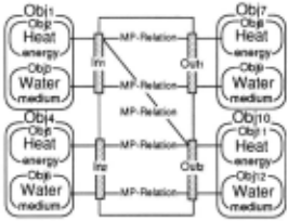
We recognize a desirable state to achieve for each com ponent in a system and the term "goal" refers to the concept. Example here is the heat exchanger in Fig.2. A heat carried by higher temperature water represented by Obh to lower one represented by Obj1o. A goal descrip tion "temperature of the output coolant(Obj1o) does not exceed five hundred degree centigrade" is an example of the goal. We represent such a desirable state by the predicate G (state).
Function type
Anne M.Keuneke classifies concept of the function into four types, such as To Make,To Control, To Maintain, and To Prevent[Keuneke, 1991]. For our representation, we give informal definition to them together with a new type, To Enable.
- To Make: To set a parameter at a desirable value.
- To Control: To shift a parameter of desirable value to an other desirable one.
- To Maintain: To keep the value of a parameter desirable for a certain period.
- To Prevent: Not to make parameters to take special values which represent no good states of the system.
- To Enable: To help the function work by making its neces sary conditions satisfied.
To Make type function which makes parameters to be in a desirable range is the basis of all other functions.
Function of a cooking stove, for example, is considered as To Make temperature of a thing put on it to be more than a certain degree. If the aim of the stove is to boil a kettle of water, then the function To Make is achieved when the temperature inside the kettle reaches one hun dred degree centigrade. On the other hand, the function of an electric water heater with a sensing device which accurately makes the temperature of the water in it to be ninety five degree centigrade is To Control.
Function of a component which keeps desired state by To Control function is To Maintain.
A component whose function is To Prevent watches and controls parameters not to go undesirable states for the system. Function of a relief valve attached to a tank is To Prevent explosion of the tank by watching pressure caused by substance inside the tank. The valve switches its behaviors: not to let the substance pass the valve out of the tank and to release the substance through the valve according to the pressure inside the tank.
Function of a pipe which helps the liquid flow IS a typical example of To Enable. Another example 1s a bias voltage of a transistor.
Focus on Compo-Objs
When we capture the main function of a component, we focus on a specific Compo-Obj 's class. We represent such a concept by the predicate 0-Focus( class of Compo Obj). Example here is a wire. As a direct current is input, it lowers the potential and at the sametime it generates heat. When we interpret the behavior of the wire as that of a resister which lowers potential of input direct current electricity, focus is given to the electric energy and 0-Focus(Electric energy) ·represents it. On the other hand, the same behavior is interpreted as that of an electric heater when we focus on the heat energy.
Focus on streams among ports
A component has several ports for input and output and streams of objects among them. A pipe, for example, streams of medium and energy are the same and it just enables the medium and energy pass from an input port to an output port and its function does not differ accord ing to whether we focus on the input port or the output port. In other cases whose streams of medium and en ergy are different from each other like a heat exchanger, energy moves from a stream of medium to another and interpretation of a component's behavior depends on the stream on which we focus. We represent such a concept by a predicate S-Focus(In Port,Out Port). An example here is behavior of a heat exchanger which transmits heat energy from higher temperature fluid to lower one whose model is represented in Fig.2. Focusing on the stream of the lower one, represented by S-Focus(ln2,0ut2) , the behavior is interpreted as "to give heat energy to the fluid" . On the contrary focusing on the higher stream, "to take heat of the fluid".
Necessity of Compo-Objs
Compo-Objs which belong to the focussed class often exist at different ports of a component from each other. Again consider a behavior of the heat exchanger in Fig.2 which focuses on heat energy existing at the four ports. The heat exchanger can be interpreted not only as a heater giving the heat energy to the colder Out Obj(ObjlO), but also as a cooler taking the heat energy of the hotter In-Obj(Obj2) away.
Difference between the two interpretations is caused by difference of the necessity of each heat energy at dif ferent port, according to the goal of the component. We represent a focused class of Compo-Obj is neces sary at a port by the predicate Need(name of the port,focused class) and not necessary by the predicate NoNeed(name of the port,focused class). When we in terpret the behavior of the component in Fig.2 as that of heater, Obju is necessary at the port Out2, thus Need(Out2,Heat)is suitable. Also when we interpret the same behavior as that of cooler, Objs is not necessary at the port Out1, thus NoNeed(Out1 ,Heat)is suitable.
2.4 Hierarchical classification of function and behavior
We have thus far defined a format and primitives to rep resent a component captured from various viewpoints. Using these viewpoints, we came up with a hierarchi cal organization of the concept of behavior and function whose portion is shown in Fig.3. The tree represents an ontology of function and behavior. Each node with a label represents a concept which can be represented by FBRL. Thus by using this tree an expert system can identify mapping an FBRL model to an appropriate be havioral or functional concept.
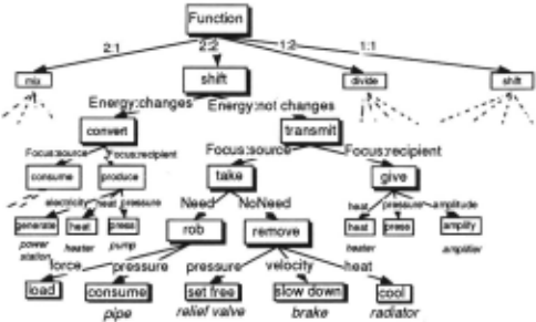
For example, a behavior of a component which deals with two In-Objs and two Out-Objs, and shift a kind of energy from one stream to the other is represented by the term "shift". The concept of "shift" is refined into "convert" if the type of the shifted energy is changed into another one, for example from heat to electricity. Otherwise it is refined into "transmit".
Classifications at the first and the second level are based on those viewpoints used for behavior description and is domain- and context-independent.
Let us focus on the stream which is source of the en ergy, represented by S-Focus(In1,0utl) where an ob ject (medium) flows from In1 to Out1 and throws en ergy to the other stream. Then the concept "transmit" is further refined into "take" since from the view point of the stream, its energy is taken by certain "transmit ting" agent, e.g. a component. The concept "take" is refined into "rob" and "remove" if the component takes an energy which is necessary for the whole system or not. The latter case, for example, is represented by NoNeed(Out1,class name of energy). The concept "re move heat energy which is not necessary for the system" is represented by a term "cool" one of whose instance is a radiator.
As discussed above, FBRL is rich in terms of concepts which represent function and behavior. This character istic of FBRL plays an important role in explanation generation because we can map behavior of a component to a proper term which represents function of the com ponent by using the tree. Also each primitive of FBRL does not rely on a specific domain, it enables reuse of a model in another domain with a little modification.
Furthermore, as demonstrated in this section, FBRL shows its potential to describe components at various levels of abstraction.
3 An Application of FBRL to Explanation Generation
Many model-based expert systems developed to date uti lize only behavioral model of the target system. This is a major reason why they have difficulty in generating ex planations at a functional level. Applying FBRL model to those expert systems, we can generate various types of explanations. This section discusses a framework of explanation generation using FBRL model , typology of explanations, and an example of generating an explana tion.
3.1 Framework for generating explanations Fig.4 shows a framework for generating explanations us ing FBRL functional models.
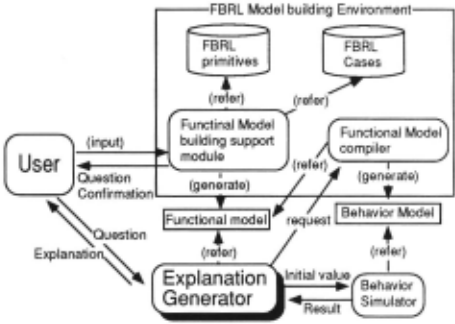
First, a designer or a knowledge engineer describes a behavior or functional model according to each goal of their tasks. The functional modeling support module helps them describe their models using the functional model library and the case base of functional models.
There are several methods of generating explanations which can be classified in terms of the timing, usage of the output explanations, and so on. Our framework in this paper adopts a method for explanation gener ation that when a user inputs his question about the system of interest , it generates an appropriate expla nation as an answer to the question. The explanation system has templates corresponding to various types of explanations. Selecting one of the templates, simulating behavior of the target system if necessary, and synthesiz ing them according to some strategies which the authors discuss in [Sasajima et al., 1994a], the explanation gen erator generates an appropriate explanations.
Applying FBRL-built functional models to explana tion task, we can generate various types of explanations which can not be generated by behavioral knowledge based systems. Stevens and Steinberg discuss typology of explanations[Stevens and Steinberg, 1981]. With fur ther consideration about the explanation classification from the view point of function and behavior, the au thors discuss the following seven types of explanations for trouble shooting expert systems in [Sasajima et al., 1994a].
Function of a component in a system:
This mentions functionality of a component. To help users understand the role of the component, the explanation mentions not only the function of the component but also how the component con tributes to the main function of the system in which the component is built.
Change of scope in explanation:
In some cases a user may ask the system to generate explanations from a macroscopic view, and in other cases he/she want a microscopic explanation. In such cases, the generator has to cope with variable grain size explanation.
Occurance of a fault:
A faulty state of a component equals to the state in which the component does not function properly. This type of explanation mentions the fault state using a functional model of FBRL.
How "To Prevent" type component works:
This type of explanation mentions functionality of a component whose function type is "To Prevent".
How an output is generated:
This type of explanation answers such questions which ask a reason why an output of a focused com ponent is generated.
Why an expected output is not generated:
Sometimes a simulation result differs from what users have expected before. This type of explana tion answers such questions that ask a reason why an expected output is not generated.
Hypothetical simulation:
Fault of a component can be represented by a pa rameter with an abnormal value. This type of expla nation mentions a simulation result which indicates the effect of the hypothetical fault.
Although we have designed a mechanism and tem plates for explanations of all of the above types, rest of this section describes how to generate an explanation about functionality of a component because of space lim itation.
3.2 Explanation of Functionality
Some users of an expert system are interested in function of a target system or its components. They may ask a question like "What is the function of the nuclear reactor in the nuclear power plant?".
To answer such a question, the system should show an explanation which explains the reactor in terms of function level vocabulary. The following is such an ex planation (Explanation 3.1) which is taken from [van Amerongen and M.Sc., 1972, pp.26-27]. The question is "How Pressurized-water reactor works as a part of an atomic power plant.?".
Explanation 3.1 {van Amerongen and M.Sc., 1972, pp.26-27}
This is the simplest form of thermal reactor, ... The heat absorbed in the core is transferred by means of a heat exchanger to the secondary circuit, where it is utilized to raise steam which drives turbines, which in turn drive the generators for producing electricity.
As the example shows, explanation of a component's function should mention not only function of the com ponent itself but also how the output of the component contributes to the main function of the whole system. At the same time the explanation should mention only the main function of the system using appropriate terms each of which represents functional level concepts. For example, Explanation 3.1 refers only five components among many components of the atomic power plant, and explains them by functional terms such as transfer,raise, and produce.
It is difficult to generate this explanation from be havior knowledge. The first reason is the difficulty of finding the causal chain of main function of the sys tem. Referring to the behavior knowledge, we can infer causal relations between the parameters, which in turn represent causal relations between components. Even if a set of input and output of the system which repre sents main function is given, it is hard to find out one causal path which represents main function of the sys tem. The difficulty appears especially when the system is complex and consists of many components, because in such cases the causal relations between the compo nents can be represented by a complex graph which has a lot of candidate paths. Selecting a right path from the candidates requires knowledge other than behavior. On the other hand, an FBRL model represents parameters which contribute to main function of the whole system using 0-Focus, S-Focus and Needs, and gives an ap propriate clue for reasoning the main function.
The second reason is the difficulty of mapping a be havior to a right functional term. Suppose a heat ex changer is used in two ways, for cooling system of an engine and for heating system of a room. In the for mer case, its behavior is interpreted as taking away the heat of the coolant of the engine. In the latter case, on the other hand, its behavior is interpreted as heating the air of the room. This difference comes from the range out of the behavior knowledge, since the behavior of the heat exchanger is the same. Generation of explanations in proper functional terms requires representation of the knowledge for behavior interpretation, and FT of the
FBRL meets this requirement.
Here we briefly mention the procedure for generating an explanation about function of a component in a sys tem.
Procedure 3.1 An outline for generating an ex planation for function of a component.
- Focus on a component whose function is to be ex plained.
- Mention function of the focused component.
- Repeat step1 and step2 while there exist compo nents which belong to the same level in structural hierarchy as the first component.
Note: Referring to the value ofNeeds,S-Focus and 0-Focus, this step does not mention function of components which do not contribute directly to the whole system's function.
- Mention function of the next component which be longs to a level of one level higher in the hierarchy.
- Repeat steps from 1 to 4 until it reaches the final output of the whole system.
Furthermore, we adopt the following two rules to make the explanation natural and concise.
1. Rule for natural explanation:
Let the component be the subject of the explana tion until the explanation about the first component finishes. Then, for explaining how the Compo-Obj output by the first component contributes to the function of the whole system, let the Compo-Obj be the subject of each explanation.
2. Rule for concise explanation:
First, explain about the "necessary" out-Obj of the first component with the medium on which the out Obj is output. Next, until a component which changes the class of the out-Obj appears, explain that the out-Obj goes through the components each of which does not convert the class of the out-Obj .
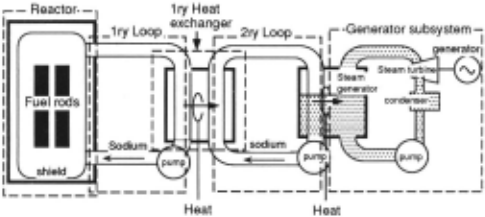
According to procedure 3.1 with adopting rule 1 and rule 2 explanation of the function of the fuel rods in Fig.5 is generated as explanation 3.2. Those terms written in bold font represent functional terms.
Explanation 3.2 :Function of the fuel rods in Fig.5
Fuel rods generate heat energy in the reactor core sub system.
The heat energy is output to the sodium of the 1ry loop. The heat energy goes through the 1ry loop, the 1ry heat exchanger, the 2ry loop, and · power generation su bsys tem. The heat energy is converted to the electricity by means of the power generation subsystem.
As discussed in this subsection, using a functional model represented by FBRL, we can simulate the main function of a system. Referring to the result of the simu lation, we can generate an explanation about function of a component of the system in terms of how the function of the component contributes to the main function of the whole system. As the generated explanation uses proper terms each of which represents function of a component, the explanation helps users understand more about the function of the component.
4 Discussion
In his work[ de Kleer, 1984], J .de Kleer proposes a method to use function of a system, which is derived from function of each component, to decrease ambiguous results of simulation. The method represents a compo nent having more than one causal relation between input and output, where function of the component is decided by selecting one of the relations. His work enables us to represent the function to achieve desirable state, which is also achieved by our representation method as discussed earlier. Furthermore, our method can explicitly repre sent functions which prevent system from falling into a no good state and side effects which may damage the whole system.
B.Chandrasekaran, et al. [Chandrasekaran et al., 1993][Iwasaki et al., 1993j[Sembugamoorthy and Chan drasekaran, 1986][Vescovi et al., 1993] capture behav ior as a series of states of the system and function as to achieve an intended desirable state. The function is achieved by the behavior and the function of each com ponent whose role is defined by the function of the sys tem. Since their representation of the function in [Chan drasekaran et al., 1993] depends on the structure of the component of the system, description of the function of two systems differs from each other if their structure dif fers from each other. Thus their representation method seems to be weak in terms of reusability of the descrip tion of function. On the other hand, our representation of the function of a component can be applied to wide range of components of the same input-output relations. An FBRL model also represents the function of a large system hierarchically.
In the above functional representation [Sembugamoor thy and Chandrasekaran, 1986], the function is described as achievin~ a desirable state. Anne M.Keuneke[Ke uneke, 1991j classifies the concept of function into four types according to some conditions, for example, the method to achieve the function, the initial condition which raises the function , the length of the term in which effect of the function is hold, and so on. She captures function as attachment of implicit assumptions to a be havior, and employs a policy to seek for the primitives to represent the assumptions. Her policy is close to that of us in this sense. Our representation includes her classifi cation and applies it to produce an abstract explanation of the function of a component.
In order to decrease the cost for diagnosis, A.Abu Hanna, et al.[Abu-Hanna et al., 1991] propose a method to describe a functional model of a system at three lev els of abstraction. We also regard that abstraction and conceptualization of a component have close relations to the function of the component, since the goal of a com ponent is always abstract one to enable interpretation of its behavior at the knowledge level. Thus we have inves tigated what primitives contribute to conceptualization of function and enumerated them, though they are not exhaustive.
M.Pegah, et al.[Pegah et al., 1993] apply the functional representation proposed in [Sembugamoorthy and Chan drasekaran, 1986] to the F / A-18 aircraft fuel system, one of the large scale and complex systems, to achieve causal understanding of the system. Our interest in application of this work goes to KC ill[Kitamura et al., 1994], a model-based diagnostic shell which currently deals with a heat transportation system of a nuclear power plant including negative feedbacks among its components.
5 Concluding remarks
We have discussed FBRL,a function and behavior rep resentation language and a vocabulary for representing components captured from the viewpoints of behavior and function. An FBRL model consists of behavior model and information for interpretation of the behav ior which we call functional topping, and each of them is explicitly represented. Thus FBRL meets our re quirement, to separate knowledge of function and behav ior of a model, and contributes to promoting reusabil ity of component models. As FBRL consists of task and domain-independent primitives it further promotes reusability. For these reasons, we can say FBRL helps model builders describe appropriate component models for each of their purposes.
The potential of a functional representation method should be evaluated by not only the number of phe nomena the method can describe but also the enhanced quality of a task by application of the model described by the method. For such an evaluation, we discussed seven types of explanations, and in this paper we pre sented an outline for explanation generation by means of FBRL models. As FBRL can represent various con cepts of function and behavior, it enables model-based expert systems to generate explanations with appropri ate functional terms.
W.Swartout et al. [Swartout et al., 1991] and T.R.Gruber et al.[Gruber and Gautier, 1993] show some techniques to explain the system's action and the knowl edge which the system possesses. It goes without saying that a domain model plays an important role in each of the frameworks, however, discussion about what in formation should be included in the model and how it should be represented is not enough. Although not ex haustive, we have discussed it more than their work in this paper and in[Sasajima et al., 1994a].
Currently we aim at applying our method to the diag nostic shell KC ill[Kitamura et al. , 1994] in two ways. One is to support users in model building and the other is to help users understand the process and result of a diagnosis by generating appropriate explanations. As for the explanation generation, explanation of occurennce of a fault in the model of a cooling system of a fast breeding reactor is implemented on UNIX workstation in common lisp. Referring to an FBRL model of the target system, it generates what fault happened to the system in terms of function of each component, and the effect of the fault. As for the other types, implementation is in progress.
Acknowledgement:
The authors are grateful to Dr. Akira Endou and Mr. Shinji Yoshikawa from Power Reactor and Nuclear Fuel Development Corporation for their help and comments on building a model of nuclear power plant.
@inproceedings{ijcai1995p235,
  title     = {FBRL: A Function and Behavior Representation Language},
  author    = {Sasajima, Munehiko and Kitamura, Yoshinobu and Ikeda, Mitsuru and Mizoguchi, Riichiro},
  booktitle = {Proceedings of the Fourteenth International Joint Conference on
               Artificial Intelligence, {IJCAI-95}},
  publisher = {International Joint Conferences on Artificial Intelligence},
  editor    = {Chris S. Mellish},
  pages     = {1830--1835},
  year      = {1995},
  note      = {Qualitative Reasoning and Diagnosis},
  url       = {https://ijcai.org/proceedings/1995/235},
}
TY - CPAPER TI - FBRL: A Function and Behavior Representation Language AU - Sasajima, Munehiko AU - Kitamura, Yoshinobu AU - Ikeda, Mitsuru AU - Mizoguchi, Riichiro T2 - Proceedings of the Fourteenth International Joint Conference on Artificial Intelligence, IJCAI-95 PB - International Joint Conferences on Artificial Intelligence PY - 1995 SP - 1830 EP - 1835 UR - https://ijcai.org/proceedings/1995/235 ER -Copied
Machine-readable versions of this paper, for tools and AI agents:





