
Motion Sketch: Acquisition of Visual Motion Guided Behaviors
Proceedings of the Fourteenth International Joint Conference on Artificial Intelligence. Action and Perception. Pages 126-131.
© 1995 International Joint Conferences on Artificial Intelligence
Abstract
Sensor and motor systems are not separable for autonomous agents to accomplish tasks in a dynamic environment. This paper proposes a method to represent the interaction between a vision-based learning agent and its environment. The method is called "motion sketch" by which a one-eyed mobile robot can learn several behaviors such as obstacle avoidance and target pursuit. A motion sketch is a collection of visual motion cues detected by a group of visual tracking routines of which visual behaviors are determined by individual tasks, and is tightly coupled with motor behaviors which are obtained by Q-learning, a most widely used reinforcement learning method, based on the visual motion cues. In order for the motion sketch to work, first the fundamental relationship between visual motions and motor commands is obtained, and then the Q-learning is applied to obtain the set of motor commands tightly coupled with the motion cues. Finally, the experimental results of real robot implementation with real-time motion tracker are shown.
- [Agre, 1995] Philip E. Agre. "Computational research on interaction and agency". Artificial Intelligence, 72:1-52, 1995.
- [Aloimonos et al., 1987] Y. Aloimonos, I. Weiss, and A. Bandyopadhyay. "Active vision". In Proc. of first /CCV, pages 35-54, 1987.
- [Aloimonos, 1994] Y. Aloimonos. "Reply: What i have learned". CVGIP: Image Understanding, 60:1:74-85, 1994.
- [Asada et al., 1994] M. Asada, S. Noda, S. Tawaratsum- ida, and K. Hosoda. "Vision-based behavior acqui- sition for a shooting robot by using a reinforcement learning". In Proc. of /APR / IEEE Workshop on Visual Behaviors-1994, pages 112-118, 1994.
- [Bellman, 1957] R. Bellman. Dynamic Programming. Princeton University Press, Princeton, NJ, 1957.
- [Connel and Mahadevan, 1993] J. H. Connel and S. Ma- hadevan. "Rapid task learning for real robot". In J. H. Connel and S. Mahadevan, editors, Robot Learning, chapter 5. Kluwer Academic Publishers, 1993.
- [Edelman, 1994] S. Edelman. "Reply: Representatin without reconstruction". CVGIP: Image Understand- ing, 60:1:92-94, 1994.
- [Held and Hein, 1963] R. Held and A. Hein. "Movement-produced stimulation in the development of visually guided behaviors". Jounal of Comparative and Physiological Psycology, 56:5:872-876, 1963.
- [Horridge, 1987] G. A. Horridge. "The evolution of vi- sual processing and the construction of seeing sys- tems". In Proc. of Royal Soc. London B290, pages 279-292, 1987.
- [Inoue et al., 1992] H. Inoue, T. Tachikawa, and M. In- aha. "Robot vision system with a correlation chip for real-time tracking, optical flow and depth map gen- eration". In Proc. IEEE Int 'l Con f. on Robotics and Automation, pages 1621-1626, 1992.
- [Maes and Brooks, 1990] P. Maes and R. A. Brooks. "Learning to coordinate behaviors". In Proc. of AAA/-90, pages 796-802, 1990.
- [P. Meer and D.Y.Kim, 1990] A.Rosenfeld P. Meer, D.Mintz and D.Y.Kim. "Robust regression methods for computer vision: A review". IJCV, 6:1:59-70, 1990.
- [Pierce and Kuipers, 1994] D. Pierce and B. Kuipers. "Learning to explore and build maps'. In Proc. of AAA/'94, pages 1264-1271, 1994.
- [Sandini and Grosso, 1994] G . Sandini and E. Grosso. "Reply: Why purposive vision". CVGIP: Image Un- derstanding, 60:1:109-112, 1994.
- [Sandini, 1993] G. Sandini. "Vision during action". In Y. Aloimonos, editor, Active Perception, chapter 4.
References were extracted automatically from the PDF and may contain errors.
Full text extracted automatically from the PDF; figures, tables and equations may differ. The PDF is the version of record.
1 Introduction
Recent research in artificial intelligence has developed computational approaches of agent's involvements in their environments [Agre, 1995] . An autonomous agent is regarded as a system that has a complex and ongoing interaction with a dynamic environment that is difficult to predict its changes. Our final goal, in designing and building an autonomous agent with vision-based learn ing capabilities, is to have it perform a variety of tasks adequately in a complex environment. In order to build such an agent, we have to make clear the interaction be tween the agent and its environment. There have been a variety of approaches to analyze the relationship between the agent with visual capabilities and its environment.
In physiological psychology, [Held and Hein, 1963] have shown that self-produced movement with its con current visual feedback is necessary for the development of visually-guided behaviors. Their experimental results suggest that perception and behavior are tightly coupled in autonomous agents that perform tasks. In biology, [Horridge, 1987] similarly have suggested that motion is essential for perception in living systems such as bees.
In computer vision area, so-called "purposive active vision paradigm" [Aloimonos, 1994; Sandini and Grosso, 1994; Edelman, 1994] has been considered as a represen tative form of this coupling since [Aloimonos et al., 1987] proposed it as a method that converts the ill-posed vi sion problems into the well-posed ones. However, many researchers have been using so-called active vision sys tems in order to reconstruct 3-D information such as depth and shape from a sequence of 2-D images given the motion information of the observer or capability of controlling the observer motion. Furthermore, though purposive vision does not consider vision in isolation but as a part of complex system that interacts with world in specific ways [Aloimonos, 1994], very few have tried to investigate the relationship between motor commands and visual information [Sandini, 1993].
In robot learning area, the researchers have tried to make agents learn a purposive behavior to achieve a given task through agent-environment interactions. However, almost of them have only shown computer sim ulations, and only a few real robot applications are re ported which are simple and less dynamic [Maes and Brooks, 1990; Connel and Mahadevan, 1993]. The use of vision in the reinforcement learning is very rare due to its high costs of sensing and processing.
In order to realize tight coupling between visual sensor and motor systems, we should consider the relationship between the low level representation of motion (motor commands to actuators) and the visual information, and develop a learning capability to abstract the low level representation into a form suitable for task accomplish ment. In this paper, we propose a method to repre sent the interaction between the agent and its environ ment which is called "motion sketch" for a real one-eyed mobile robot to learn several behaviors such as obsta cle avoidance and target pursuit. A motion sketch is a collection of visual motion cues detected by a group of visual tracking routines of which visual behaviors are de termined by individual tasks, and is tightly coupled with motor behaviors which are obtained by Q-learning, a most widely used reinforcement learning method, based on the visual motion cues.
In the next section, we describe the basic idea of the motion sketch for our example task. In section 3, we give a method for acquisition of the fundamental rela tionship between visual motion cues and robot motor commands. In section 4, we describe a reinforcement learning method to obtain target pursuit behavior and obstacle avoidance one. Then, in order to demonstrate the validity of our method, we show the experimental results of the real robot implementation with a real-time visual motion tracker [Inoue et al., 1992] in section 5.
2 Motion Sketch
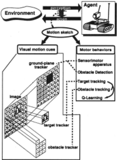
The interaction between the agent and its environment can be seen as a cyclical process in which the environ ment generates an input (perception) to the agent and the agent generates an output (action) to the environ ment. If such an interaction can be formalized, the agent would be expected to carry out actions that are appro priate to individual si~uations. "Motion sketch," we pro posed here, is one of such formalizations of interactions by which a vision-based learning agent that has real-time visual tracking routines behaves adequately against its environment to accomplish a variety of tasks.
Figure 1 shows a basic idea of the motion sketch. The basic components of the motion sketch are visual motion cues and the motor behaviors.
Visual motion cues are detected by several visual tracking routines of which behaviors (called visual be havior) are determined by individual tasks. The visual tracking routines are scattered over the whole image and an optical flow due to an instantaneous robot motion is detected. In this case, the tracking routines are fixed to the image points. The image area to be covered by these tracking routines are specified or automatically de tected depending on the current tasks, and the coopera tive behaviors between tracking routines are performed for the task accomplishment. For the target pursuit task, the multiple templates are initialized and every template looks for the target to realize stable tracking. In the task of obstacle detection and avoidance, the candidates for obstacles are first detected by comparing the optical flow with that of non-obstacle (ground plane) region, and then the detected region is tracked by multiple templates each of which tracks the inside of the moving obstacle re gion.
The motor behaviors are sets of motor commands ob tained by Q-learning, based on the detected motion cues and given task. The sizes and positions of the target and the detected obstacle are used as components of a state vector in the learning process.
Visual and motor behaviors work in parallel in the image and compose a layered architecture. The visual behavior for monitoring robot motion (detecting the op tical flow on the ground plane on which the robot lies) is the lowest and might be subsumed in part due to oc clusion by other visual and motor behaviors for obstacle detection/avoidance and target pursuits which might oc clude each other.
Thus, the "motion sketch" represents the tight cou pling between the agent that can perform an appropri ate action sequence so as to accomplish the given tasks and its environment which is represented by visual mo tion cues from the visual tracking routines. The motion sketch does not need any calibrations nor any 3-d recon struction so as to accomplish the given task. The visual motion cues for representing the environment does not seem dependent on scene components nor limited to the specified situations and the task. Furthermore, the inter action is quickly obtained owing to the use of real-time visual tracking routines.
The behavior acquisition scheme consists of the fol lowing four stages:
- stage 1 Obtaining the fundamental relationship be tween visual and robot motions by correlating mo tion commands and flow patterns on the floor with very few obstacles.
- stage 2 Learning target pursuit behavior by tracking a target.
- stage 3 Detection of obstacles and learning an avoid ance behavior.
- stage 4 Coordination of the target pursuit and obstacle avoidance behaviors.
At each stage, we obtain the interaction between the agent and its environment.
3 Obtaining sensorimotor apparatus
Before introducing the method for obtaining sensorimo tor apparatus, motion mechanism and visual tracking routines we use in the experiment are shown.
(A) PWS system:
The robot has a Power Wheeled Steering (hereafter PWS) system driven by two motors into each of which we can send a motor command, independently. The ve locities of translation v and rotation w of the robot can be represented by two motor commands, more correctly two angular velocities w1 and Wr·
In our experment, we quantized wl(r) into five levels which correspond to quick forward (qf), slow forward (sf), stop (st), slow backward (sb), and quick backwrad (qb), respectively. Totally, we have 25 actions. Note that the robot does not know even any physical meanings of these actions.
(B) Multiple visual tracking routines:
To detect changes due to an instantaneous robot mo tion, we use real-time. visual tracking routines which can track about 140 windows (each window consists of 8 by 8 pixcels) in real-time (video rate) by using a motion esti mation processor (MEP) [Inoue et al., 1992). Searching area is 16 by 16 pixcels and the MEP outputs the loca tion of each window where the following matching error (SAD: sum of absolute difference) is minimum.
where R[x, y], M[x, y], and D[x, y] denote a reference block, a matching block, and an array of SAD, respec tively. The visual tracking routines are used to obtain an optical flow of the floor, to track a target specified by a human operator, and to detect and avoid obstacles. We detect a motion vector in an image by applying the block matching process with the reference block (t = ti) and the search window images (t = ti+I) continuously. Thus, we can obtain the optical flow vectors in the image at any time.
We assume that the robot is given no knowledge of the structure of its sensory system nor of the effects. We extend the method [Pierce and Kuipers, 1994) as follows:
- Instead of sonar information (3-D range informa tion), we use an optical flow of the floor which can be obtained by multiple visual tracking routines.
- In order to remove fluctuations of flow pattern of each action due to the environmental factors, we set up the environment with almost no obstacles. In av erageing flow patterns, we used the least median of squares method [P. Meer and D.Y.Kim, 1990) (here after, LMeS method) to remove the outliers due to noise or small obstacles.
3.1 Optical flows due to agent actions
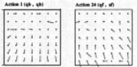
We place 49(7 x 7) visual tracking routines to detect changes in the whole image. Therefore, we obtain an optical flow composed of 49 flow vectors. In the en vironment without obstacles, the robot randomly se lects a possible action i( rli, Tri) among the action space rli,Tri E {qf,sf,st,sb,qb}, and executes it. While ran domly wandering, the robot stores the flow patterns Pi due to its actionsi (i = 1 ""25). After the robot per formed all possible actions (here, 25 actions), we obtain the averaged optical flows Pi removing the outliers due to noise or small obstacles based on the LMeS method.
"' u ~l
Figure 2: Examples of averaged optical flows
3.2 Aquisition of principal motion patterns
Using the averaged optical flows obtained in the last sub section, we acquire principal motion patterns which char acterize the space of actions. This is done by analyzing the space of averaged optical flow that robot is capable of producing. We want to find a basis for this space, i.e., a set of representative motion patterns from which all the motion patterns may be produced by their linear combinations. We can obtain representative motion pat terns by using Principal Component Analysis that may be performed using a technique called Singular Value Decomposition(hereafter SVD).
[Tomasi and Kanade, 1992) also utilize the SVD for analyzing the image sequence mainly attempting at re covery of the 3-d geometry by the SVD technique. Here, we attempt to obtain the sensorimotor apparatus by the technique.
The sample values of Pi (the averaged optical flow) corresponding to the actioin i( T!i, Tri) are organized as the rows of matrix P. There are 25 rows each of which have 98 components ( 49 flow vectors each of which con sist of two components). The SVD of Pis
where S is a diagonal matrix whose elements are the singular values of P, and the rows of ET are the desired orthonormal basis vectors. Here, the number of averaged optical flows, m = 25 and the number of components in each averaged optical flow (two for each local visual tracking routine), n = 98. U is the orthogonal matrix in terms of the row. The averaged optical flow Pi can be described as a linear combination of the vectors in ET from the quation (1), using the K principal components:
Thus, we have found a basis set (the row vectors of ET) for the space of averaged optical flow. In fact, we obtain 26 principal components by caluculating SVD for the P which consist of 25 flow patterns.
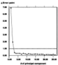
From these 26 principal components, we have to se lect some principal components which are necessary for characterizing the space of actions. Here, we decide the number of the principal components as follows. E(K) is the error function in the case of describing the averaged optical flow Pi as a linear combination of K principal components.
Furthermore, using this error function E(K), tlE(K) is
tlE(K) indicates the decreasing degree of E(K) by us ing the 1 "' K principal components for obtaining the approximation of Pi
Figure 3 shows the relationship between tlE(K) and K. From this figure, it is sufficient to use the first two principal components for describing Pi as a linear combi nation of principal components. That is, including more than the third pricipal components does not have influ ence on decreasing more than 1 pixel error per a point.
Thus, vector Pi may be approximated by
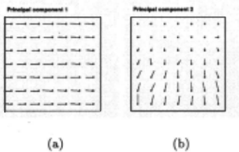
The first two principal components obtained in the real experiment are shown in Figure4. Obviously, the first (a) corresponds to a pure rotation and the second (b) to a pure backward motion.
--· --·
Next step is to make a relation between the possi ble actions Pi by representing each of them in terms of the coeficient ai = uikSk in the action space which consists of two principal components. The relation be tween possible actions of the real robot are shown in FigureS, where the number indicates the action index i ( i = 1 "' 25).
- , ..... , '
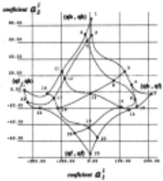
Thus, we can compress the visual motion patterns by the obtained fundamental relationship and then use it to include the ego-motion information in the internal state space of the agent in the learning process.
4 Behavior acquisition based on visual motion cues
4.1 Basics of Reinforcement Learning
Reinforcement learning agents improve their perfor mance on tasks using reward and punishment received from their environment. They are distiguished from su pervised learning agents in that they have no "teacher" that tells the agent the correct response to a situation when an agent responds poorly. An agent's only feed back indicating its performance on the task at hand is a scalar reward value. One step . Q-learning [Watkins, 1989] has attracted much attention as an implementa tion of reinforcement learning because it is derived from dynamic programing [Bellman, 1957]. The following is a simple version of the 1-step Q-learning algorithm we used here.
Initialization: Q - a set of initial values for the action-value function (e.g., all zeros).
Repeat forever:
- s E S - the current state
- Select an action a E A that is usually consistent with the policy f but occasionally an alternate.
- Execute action a, and let s' and r be the next state and the reward received, respectively.
- Update Q(s, a):
4.2 Target tracking behavior acquisition
According to the above formalization of the state set , the action set, and other functions and parameters, we apply the Q-learning to a target pursuit task.
We use the visual tracking routines in order to pur sue a target specified by a human operator and obtain the information about the target in the image such as its position and size which are used in the Q-learning algorithm for acquisition of target pursuit behavior.
Visual functions of tracking routine
Our visual tracking routine has the following visual func tions.
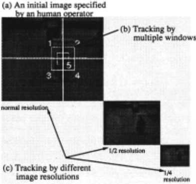
- A target image is specified by a human operator in advance as shown in Figure 6(a). A target is tracked by an object tracker which consists of 5 visual track ing routines fixed together as shown in Figure 6(b). Even if the pattern of the target is deformed by oc clusion or the vibration of the robot body, the object tracker can continue to the track target owing to the use of multiple visual tracking routines.
- We prepare three kinds of resolutions(a normal, a half and a quarter resolutions) as shown in Figure 6(c). Even if the the pattern of the target becomes large or small, the object tracker can continue to track it by changing the image resolution and the search area for the block matching.
- When the target detection fails, a search-whole image routine is called in order to detect the target again outside the pre-defined search area.
We define the state of the target in the image based on its position and size (three levels) obtained by the visual tracking routines.
State and action spaces in Q-learning
In order to apply the Q-learning scheme to a target pur suit task, we define a number of sets and parameters. The state of the target, S in the image is quantized into 9 sub-states, combinations of three positions (left, cen ter, and right) and three sizes (large (near), medium, and small (far)). Similarly, changes in position and size of the target in the image are quantized into 9 sub-states, com bination of three states for position changes (move left, no move and move right) and three states for size changes (enlarge, no change, shrink). We add two lost situations (target is lost into the left side or the right side) in the state space. Futhermore, we add the action index (to tally 25 actions) just taken on observing the current sit uation into the state space in order that we deal with the so-called perceptual aliasing problem. That is, induing the self-motion index into the agent's internal state en ables the agent to discriminate both changes caused by the observer motion and an actual changes happened in the environment.
Totally, we have 92x25 states in the set S. We have 25 actions in the action set A . We assign a reward value 1 when the robot touched the target or 0 otherwise. A discounting factor 'Y is used to control to what degree rewards in the distant future affect the total value of a policy. In our case, we set the value a slightly less than 1 ('Y = 0.9).
4.3 Obstacle avoidance behavior acquisition
(a) Detection and tracking of obstacles by flow differences
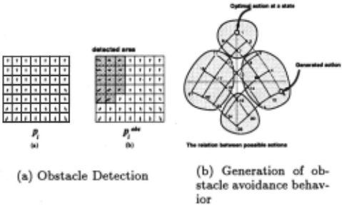
We know the flow pattern Pi corresponding to the action i in the environment without any obstacles. The noise included in Pi is not so much, because this flow pattern is described as a linear combination of the two principal motion vectors. Therefore, it makes motion segmenta tion easy. Motion segmentation is done by comparing the flow pattern Pi with the flow pattern P'tbs which is obtained in the environment with obstacles. The area in the P'lbs is detected as the area for obstacle candidates if its components are different from that of Pi· This infor mation (position and size in the image) is used to obtain the obstacle tracking behavior. After obtacle detection, the visual tracking routines are set up at the positions where the obstacle candidates are detected and the re gions are tracked until the region disappears from the image.
(b) Learning obstacle avoidance behavior
Learning to avoid obstacles consists of two stages. First, the obstacle tracking behavior is learned by the same manner as in learning the target pursuit behavior. Next, the obstacle avoidance behavior is generated by using the relation between the possible actions and the obsta cle tracking behavior as follows : (1) the relationship be tween the possible actions is divided into four categories by clustering the action space in terms of the coefficients (ai,a;) (See Figure7(b)), (2) the obstacle tracking be havior is mapped on the relationship, and the category ctwhich includes the obstacle tracking action is found, (3) the obstacle avoidance action is selected among the categories except for ct. More correctly, the obstacle avoidance action is obtained by finding the action hav ing the smallest action-value function with respect to the obstacle tracking behavior among the categories except for ct.
5 Experimental results for a real system 5.1 A configuration of the system
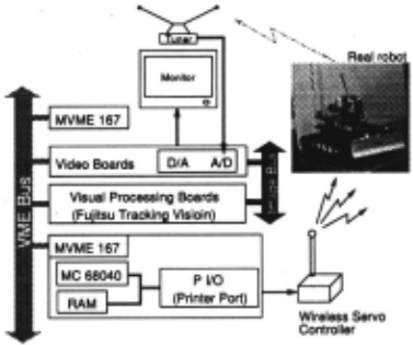
Figure 8 shows a configuration of the real mobile robot system. We have constructed the radio control system of the robot [Asada et al., 1994]. The image processing and the vehicle control system are operated by VxWorks OS on MVME167(MC68040 CPU) computer which are con nected with host Sun workstations via Ether net . The image taken by a TV camera mounted on the robot is transmitted to a UHF receiver and subsampled by the scan-line convertor (Sony Corp.). Then, the video sig nal is sent to a Fujitsu tracking module. The tracking module has a function of block correlation to track some pre-memorized patterns and can detect motion vectors in real time. In the Figure 8, a picture of the real robot with a TV camera (Sony camera module) and a video transmitter is shown.
5.2 Target tracking with no obstacles
The experiment consists of two phases: first, learning the optimal policy f through the computer simulation, then apply the learned policy to a real situation. Figure 9 shows a sequence of images where the robot succeeded in pursuing a target. The top of Figure 9 (a) shows the initial position of the target . The top figures in the Fig ure 9 (b), (c) and (d) shows the processed images. The white rectangle in each image shows the target position which is tracked. The white lines in these images show the optical flows. In this way, based on the hierachical architecture of the visual tracking routine, we can per form the target tracking and the optical flow detection in parallel on the real system.
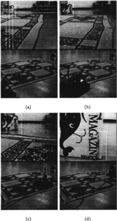
5.3 Obstacle detection and avoidance
Figure 10 shows a sequence of images where the robot . succeeded in avoiding a moving obstacle. The top figures in the Figure 10 (a) and (b) show the processed images. In (a), the rectangles indicate the obstacle candidate re gions.
6 Concluding Remarks a·nd Future Work
As one of the method for representing the interaction be tween the agent and its environment which enables the situated agents to behave adequately against the exter nal world, we proposed "motion sketch" which is inde pendent of scene components and tightly coupled with motor commands. Now, we are planning to develop a new program which tightly connects MaxVideo 200 and Fujitsu Tracking module to speed up and finish the final stage of behavior integration.
@inproceedings{ijcai1995p17,
  title     = {Motion Sketch: Acquisition of Visual Motion Guided Behaviors},
  author    = {Nakamura, Takayuki and Asada, Minoru},
  booktitle = {Proceedings of the Fourteenth International Joint Conference on
               Artificial Intelligence, {IJCAI-95}},
  publisher = {International Joint Conferences on Artificial Intelligence},
  editor    = {Chris S. Mellish},
  pages     = {126--131},
  year      = {1995},
  note      = {Action and Perception},
  url       = {https://ijcai.org/proceedings/1995/17},
}
TY - CPAPER TI - Motion Sketch: Acquisition of Visual Motion Guided Behaviors AU - Nakamura, Takayuki AU - Asada, Minoru T2 - Proceedings of the Fourteenth International Joint Conference on Artificial Intelligence, IJCAI-95 PB - International Joint Conferences on Artificial Intelligence PY - 1995 SP - 126 EP - 131 UR - https://ijcai.org/proceedings/1995/17 ER -Copied
Machine-readable versions of this paper, for tools and AI agents:





