Constraint Based Automatic Construction and Manipulation of Geometric Figures
Proceedings of the Thirteenth International Joint Conference on Artificial Intelligence. Intelligent Tutoring Systems. Pages 453-458.
Abstract
An imJX>rtant comJX>neQt of an Intelligent Tutoring System (ITS) for teaching geometry is its capacity to transform a figure into as many different figures as JX>Ssible, yet all of which respect the same underlying logical specification. Given a logical specification for a figure, (i) a figure can be constructed automatically from the objects and properties in the speP.fication; and (ii) once constructed, one can transform a figure through displacement of any of its objects and still obtain a figure that respects the specification. For a student user, this feature provides an invaluable tool for graphical exploration and discovery of properties induced by the logical specification. Our problem domain is automatic construction of figures; and we address this issue in restricted cases using Constraint Logic Programming. We present solutions to cases in which figures can be constructed automatically and in which there is also a natural notion of completeness for our system. For this automatic figure construction system, we describe an implementation, written in Prolog III, which makes use of both constraints and coroutines provided in the language. Results of experimentation are also included, as well as ways in which the system can be extended to handle non restricted cases.
- Allen, R., Nicolas, P., Trilling, L., "Figure Correctness in an Expert System for Teaching Geometry," Proceedings of the eight biennial conference of the Canadian society for computational studies of intelligence, Ottawa, May 22-25, 1990, pp. 154-160.
- Allen, R., Nicolas, P., Trilling,. L., "Logical Specification of Figures for Teaching Geometry," Proceedings COGNITIVA 87 Conference, Paris, May 18-22, 1987.
- Baulac, Y., Bellemain, F ., Laborde, J.M., CABRI The Interactive Geometry Notebook, Brooks/Cole Publishing Company, Pacific Grove, CA, 1992.
- Borning, A., "The programming language aspects of ThingLab, a constraint"oriented simulation laboratory," ACM TOPLAS, vol. 3, no. 4, 1981.
- Carrega, J .C., Theorie des corps, Ia regie et le compas, reedition, Herman, Paris, 1989.
- Chou, S.C., Mechanical Geometry Theorem Proving , Reidel Publishing, Norwell, MA, 1988.
- Colmerauer, A., "Prolog Ill," Communications of the ACM, vol. 33, no. 69, 1990.
- Hollman, J., Langemyr, L., "Algorithms for Non-Linear Algebraic Constraints,", Constraint Logic Programming: Selected Research, Colmerauer, A., Benhamou, F., eds., MIT Press, (to appear).
- Hong, H., "RISC-CLP(Real): Logic Programming with Non-linear constraints over the Reals," Constraint Logic Programming: Selected Research, Colmerauer, A ., Benhamou, F. , eds., MIT Press, (to appear).
- Kutzler, B., "Deciding a Class of Euclidean Geometry Theorems with Buchberger's Algorithm," Revue d'lntelligence Artificielle, vol. 4, no. 3, Hermes, Paris, 1990.
- Nicolas, P., Construction et verification de figures geometrique dans le systeme MENTONIEZH, These de l'Universite de Rennes I, 1989.
- Older, W ., Vellino, A., "Constraint Arithmetic on Real Intervals," Constraint Logic Programming: Selected Research, Colmerauer, A., Benhamou, F., eds., MIT Press, (to appear).
- Roller, D., Shonek, S., Verroust, A ., "Dimension-driven geometry in CAD: a survey," LIENS, ENS Paris, 1988.
- Schreck, P., "Automatisation des constructions geometriques sous constraintes," Actes des Deuxieme Journees EIAO de Cachan, Baron, M., Nicaud, J.F., eds., ENS Cachan, 1991.
- Wu, W., "On the decision problem and the mechanization of theorem proving in elementary geometry," Sci entia Sinica, vol. 21, 1978.
References were extracted automatically from the PDF and may contain errors.
Full text extracted automatically from the PDF; figures, tables and equations may differ. The PDF is the version of record.
1 Introduction
Microworlds and intelligent tutors designed to help teach secondary students how to solve problems in geometry make tools available (1) to aid in the construction of geometric figures that conform to a specification provided beforehand by a teacher, (2) to stimulate discovery of important geometric properties represented in such figures, and (3) to guide the organization of proofs. In previous work four main components of such systems have been identified [Allen et al., 1990]:
- Figure acquisition: The student first constructs a figure which conforms to a specification provided by the teacher. The level of the geometric theory made available to students for carrying out their constructions can be adjusted by the teacher. The construction of a correct figure is considered as confirmation of the comprehension by the student of the hYJX>theses of the problem.
- Figure appropriation: The student can graphically transform the figure while its logical properties are preserved. On the one hand, the student can thus detect interesting invariants and, on the other hand, can observe graphically the impact of suppressing a hyJX>thesis.
- Property exploration: The student reacts to system proJX>sed interesting properties by using theorems furnished by the teacher.
- Proof organization: The student, utilizing facts discovered during the previous steps and theorems furnished by the teacher, constructs a proof which is verified by the system.
In this paper we are primarily interested in the figure appropriation comJX>nent which can be approached from two different perspectives, one "imperative geometric programming" and the second "declarative geometric programming." The imperative geometric programming approach asks the student to exhibit a (procedural) construction of a figure which conforms to a previously given specification. Subsequent transformations of the figure can then be obtained by moving objects found in the construction. However, in some cases the same object can or cannot be moved, depending on the order in which the object was created during the construction. For example, consider the construction: construct line D1, then line D2, and thirdly the JX>int Pas the intersection ofDl and D2. Dl and D2 can be moved but not P since it is fixed by D1 and D2; on the other hand, if P had been constructed before either D1 or D2, then it could have been moved. As is not surprising, imperative geometric programming is sensitive to the order in which geometric objects are drawn. Cabri geometre [Baulac et al., 1992] is an important example of a system using the imperative approach.
Declarative geometric programming differs naturally from imperative programming in that a user is asked to provide only the logical specification of the figure, not the order in which objects are to be constructed. The system automatically constructs the figure, if possible, from whatever geometric objects are given. The figure can then be transformed by fixing all of the objects except the one that is used for doing the figure displacement. Transformed figures still respect the specification. Using the declarative mode for the example in the preceding paragraph, any of the three objects could be chosen, independently of order constructed, to be moved in order to provide a transformation of the figure. This capability has significant implications for the design of teaching (didactic) situations which stimulate learning. Being able to animate a figure in all possible ways gives a student the possibility of guessing more properties than if she were restricted to the animation induced by a particular order of construction found in an imperative geometric programming approach. Furthermore, it becomes easier for a teacher to reinforce or to weaken a hypothesis: one has only to modify the specification, not the order, in order to obtain a new construction and subsequent animation.
The first of the two goals of this paper concerns the automatic construction of geometric figures from (logical) specifications. Even for a relatively simple specification language, one expressing merely the distance between two points, long, unsolved, and difficult problems have remained: for example, the construction of a regular pentagon. For our purposes, we adopt here a pragmatic point of view. It consists in believing that augmenting significantly the power of imperative geometric programming by making possible more animation (than is possible in an imperative approach) is an interesting achievement. It also resides in not being so ambitious as to want to provide a construction (even if one exists) for every specification. We adopt a declarative approach and the issue, from a computer science standpoint, is to define an adequate completeness for our system. This means that its limits must be precisely and clearly defined. To this end, we express this completeness in terms of the classical geometric tools (ruler, square, compass).
The second of our goals is to show that Constraint Logic Programming (CLP) is an adequate AI tool for supporting declarative geometric programming. We use the following advantages of the CLP language Prolog III [Colmerauer, 1990]: (i) modularity expressed through rules permits easy extension or restriction of the system functionalities; (ii) calculus of constraints as exact solutions of linear constraints is provided by the language itself and resolution of the non-linear constraints that we propose can be expressed using this calculus; (iii) non determinism and suspended execution of goals (the freeze feature) permit a straightforward implementation of the claimed completeness. We will also discuss performance, which appears to be at least acceptable and able to be improved.
2 Linear case
Computer implemented Student Construction Languages (SCLs) [Allen eta/., 1987] provide the basis for imperative geometric programming. Such languages provide an interface with which the user, typically a school student, (1) indicates on a menu what object (point, line, ray, segment, circle) she wants to draw on the given graphics medium; (2) draws the object; and (3) expresses the logical properties (name, belonging to another object, parallel to, perpendicular to, is the midpoint between, is the distance from, ... ) of the drawn object with respect to already-drawn objects. The most important characteristic of the interface is that each operation must be realizable using drafting table instruments (ruler with translation, square, compass) . Consequently, a user is limited in the constructions she can carry out. For example, she cannot construct a line passing through three points although she could create a line and afterwards three points belonging to it. Such an interface has been directly implemented in the s y s t em MENTONIEZH [Nicolas 1989] and similar interfaces are implemented with the use of a mouse in the system Cabri geom~tre.
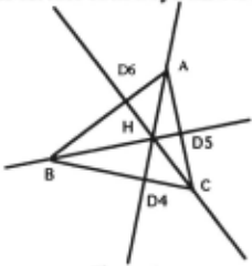
In the problem of constructing the intersection H of the heights of a triangle ABC, a possible construction by a student might be encoded using the following sequence of steps:
create point A, create point B, create point C
create segment S 1 with endpoints A and B
create segment S2 with endpoints A and C
create segment S3 with endpoints B and C
construct line D4 passing through A and
perpendicular to the support of S 1
construct line D5 passing through B and
perpendicular to the support of S2
construct line D6 passing through C and perpendicular to the support of S3
construct point H as intersection of lines D4 and D5 It is clear that this sequence gives a procedure for constructing a geometric figure which often is displayed as two-dimensional graphical output (see Figure 1). Cabri geom~tre menus provide a language for carrying out such a procedure. The user of Cabri-geom~tre can relocate (drag) any one of the vertices and the system will redraw the figure while respecting the construction. However, any attempt to move H, the intersection of the heights, will be refused since the construction of H depends on the vertices which, according to the procedure, have to be created before the intersection. Then a new construction has to be proposed to move H. In a declarative programming mode, this need not be so and we will discuss such a system below.
Our approach to declarative geometric programming is motivated in part by languages called Classroom Description Languages (CDLs) [Allen eta/., 1987]. Such languages are inspired from those found in· geometry textbooks. As an example of such a language, consider the following simple one composed of the predicates: point(M), line(L), segment{S, A, B), M t L, M t S, L .l L' , L II L' where A, B, Mare points, Land L' are lines, and Sis a segment. A specification for constructing a figure then becomes a conjunction of atomic formulas composed from these predicates. The specific ordering of the atomic formulas has no effect on the figure constructed. In the case of the intersection of the heights of the triangle problem, using our declarative geometric programming system, the figure can be constructed automatically from any three of the points A, B. Cor H, given the following specification:
point(A), point(B), point(C), point(H), line(D4),line(D5),line(D6), segment(S l,A,B), segment(S2,A,C), segment(S3,B,C), A e 04, B e D5, C e 06, H e 04, H e D5, H e D5, 04 .l S3, D5.l S2, D6 .l Sl
A notable difference between this solution and the imperative one is that the point H can be relocated. One has to indicate what are base elements (for example A, B, and and H) and which among the base elements is to be used for dragging (say H). Our system then will automatically redraw the figure as we drag on H, all the while respecting the specification. It is clear that such a system can readily be implemented in Prolog III since all equations derived from the above property specifications (with any three of the points A, B, C, or H fixed) are linear (e.g., for A£ 04, the equation is y-ax-b=O, where x,y are the coordinates of A and a,b are slope, and intercept of 04). Moreover, in Prolog III, any calculations carried out on the equations are exact. This means-and this is extremely important-that (linear) overconstrained specifications can be accepted. Overconstraints are those which are not necessary for the construction of the figure, but which must nevertheless be verified. Such specifications arise very naturally. For example, the preceding specification, where A, Band Care fixed, belongs to this category; the fact that H is the intersection of three lines has to be verified.
Curiously, it is not easy to characterize the possible constructions in terms of geometrical instruments. For example, one might be tempted to conjecture that all "ruler only" constructions can be solved by linear algebra. This is not true, a simple counter-example being the following: Given any three points and any three lines that intersect in a common point, construct a triangle with vertices on the lines and sides passing through the points. This construction is known to be feasible using a ruler alone [Carrega, 1989]; however the equations that underlie the properties in the construction are not linear.
3 Non-linear case
Problems become a fortiori non-linear if we add language formulas of the type IABI = d to our specification. The resolution of systems of such equations, namely equations of lines (y=ax+b) and equations of circles ( (x-x'9+(y-y')2d2=), is described below. Their satisfiability is known to be decidable; and it is known in that a construction using ruler and compass can be found if it exists (whereas, in the general case, construction has to be carried out numerically). Although these important theoretical results are difficult to exploit practically, our approach provides solutions in some important and interesting cases.
Our objective is essentially to try to achieve a significantly better result than that given by imperative geometric programming. The crucial issue is giving a clear semantics to the tools we provide rather than attempting to construct from every specification, regardless of the price. From this point of view, a very simple idea comes to mind, namely, giving a "closed world compass and ruler" completeness to our system. In other words, if a construction with ruler and compass exists using only the elements occurring in the specification, then a construction is provided; otherwise, nothing is guaranteed.
In order to provide such power of construction, the system must have the capability of computing intersections of circles and lines and intersections of circles and circles (intersections between lines are computed by solving linear equations). In fact, computing intersections of two circles can be reduced to computing intersections of a line (the common chord of the intersecting circles) and of either of the circles. The requirements for attaining our desired power of construction can therefore be stated in the following terms:
- For all intersections of circles, add their common chords. That is, if the specification contains the two formulas IMl Ml = rl and 1M2 Ml = r2 and if M is not a base point, then the common chord of circle of center Ml with radius rl and of circle of center M2 with radius r2 is added to the specification. This means that a constraint implying that M belongs to the common chord of the two circles is added.
- The system of equations derived from two formulas such as IOMI =rand M £ D, where 0, rand Dare known, must be solvable. In fact, we adopt the more general approach in which we check to see whether every variable x, xO, y, yO, r in an equation (x-x0)2 + (y-y0)2 = r2 of a circle is known or is a linear function of the same variable u. In such cases the second degree equation in u is solved very simply. This approach permits the solution of problems not solvable in a strict, closed world, compass and ruler perspective. Note also that no more objects are introduced than those present in the specification or those introduced implicitly by adding the common chord of two possible circles.
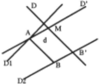
An example of a non trivial problem (typically asked of 13-14 year olds in French schools) follows : Suppose that the lines D. Dl, and D2 along with the distance d be given; construct points A and B such that IABI = d, A £ Dl , B E D2, AB II D. Let A = (x,y), B = (x', y') and let the lines Dl, 02, AB and D be defined by (slope,intercept) coefficient pairs (al , bt), (a2 , ~).(a, b) and (a', b'), respectively. From the properties given we obtain the system of equations:
with d, a1, b1, a2. b2 , a' and b' given. There are six unknowns x, y, x', y', a and b. Equations (2) and (3) provide a linear relation between y and x, on the one hand, and a linear relation between x' and y', on the other. Similarly, equations (4) and (5) provide other linear relations between x andy and between x' andy'. These four equations, together with equation (6), allow us to solve for y, x' and y' as linear functions of x. This in tum allows equation (1) to be solved for x. It is interesting to note that an imperative solution to this problem using compass and ruler requires introduction of a new line: Let B' E D2, B' ED, and M such that IB'MI
=d. Then introduce the lineD' II D2 with M £ D' and we obtain A £ D 1.
Of course, our method cannot solve a very difficult problem such as the construction of a regular pentagon (typically asked of 17-18 year olds in French schools, with numerous hints provided), which has a very simple specification: IA1A2I= IA2A3I = IA3A4I = IA4A5I = IAsA1I, lOA 1l= IOA2I = IOA3I = IOA4J = lOA 5I. On the other hand, some problems that arise more commonly are not solvable using our method, but would be if a little more geometric information were provided in the specification. For example, to construct a tangent from a given point P to a given circle of center 0 and radius r, the specification is expressed: Given points 0 and P and distance r, IOMI = r and OM .l PM. The reason our system is unable to do the construction is that the system does not know that M belongs to the circle whose diameter is OP.
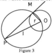
This last example suggests a simple way of overcoming the lack of geometric information available to our system: ask the user's help in providing it. Since the user is supposedly working with the system to obtain more flexibility in animating her figures, this suggests that she would be willing to help the system achieve the better results. More exactly, we are asking the user to provide the system with overspecifications. In our last example, if we add the overspecifications l=midpoint(O,P) and 1011 = IIMI, then M can be constructed as the intersection of two circles. Such overspecifications are of course translated into overconstraints, which leads us to the issue of solving overconstraints in non-linear cases.
4 Overconstrained case
Overconstraints arise naturally and for important reasons; they present obstacles which cannot be avoided. Not only do they provide means whereby users can interact intelligently to help the system, but they also can be very naturally and unconsciously introduced into a specification, as in the case of the intersection H of the heights of a triangle. Thirdly, they might be introduced automatically by our system as it creates new lines (common chords of intersecting circles) when needed. To provide an example of the third point above, let us consider the following specification: Given the points M1 and M2 and the distances r1 and r2,let IM1 Ml = r1 and 1M2 Ml = r2 (M is not known). Creating the common chord D of the circle C1 with center M1 and radius r1 and of the circle C2 with center M2 and radius r2 means adding the overspecification M £ D. Then M is (over)constrained to be the intersection of three figures (the two circles and D) which translates into three equations to be satisfied.
Our current approach attempts to address the overconstraint issue in what might at first appear to be a rather drastic way: all overconstraints associated with a possible construction are assumed always to be satisfied. In other words, a construction is provided even if some properties found among those in the specification and those introduced automatically as overconstraints.are not verified. Our decision to satisfy all overconstraints is based on the simple fact that, whereas the calculations in the linear case are exact (Prolog III), our calculations on the extension of rationals are not exact. For example, if the solutions to two quadratic equations are known to be the same, we cannot be assured of always computing them equal numerically. Of course, this way to deal with overconstraints is correct if the only ones to consider are those introduced automatically by the system (none would be introduced by the user) since it is a theorem that a point belonging to two circles belongs to their common chord.
Technically, the problem resides in recognizing those equations which form overconstraints for a computed construction and in communicating them to the user. In the preceding example, if M is computed as the intersection of D and C 1, the overconstraint to be communicated is then the equation derived from 1M2 Ml = r2. This problem can be solved easily by determining those equations which do not contain any unknown variable. Such equations only represent properties to be satisfied and are not used to compute any unknowns; thus, they are overconstraints.
The state of the art provides us with direction and hope for resolving the problem of solving overconstraints in general: such problems require symbolic computation. The method for proving geometric properties proposed by Wu [1978] is the most promising to date. However, even with this approach, there is a significant restriction, namely, that the hypotheses be written in a constructive manner. Ten rules are used to ensure that the hypotheses are written in a constructive manner. The resulting equations must represent properties of the type: an arbitrary point, an arbitrary line, a line passing through a point, a point on a line, the intersection of two lines, or the intersection of two circles. It is clear that the individual using this method must intervene to make sure that the hypotheses are in the correct format. In the case where they are not, the answer is not guaranteed. In Wu's method, a construction of the figure representing the hypotheses must be exhibited and the equations describing this figure derived from such a construction. This is exactly what our approach does, since the overconstraints are checked once the user has found a construction of all the geometric elements in the specification. So, Wu's algorithm could be applied in our case. From a practical standpoint, Wu's method seems to be the more effective and the least costly [Chou, 1988]. In any case, since our goal is mainly animation, the checking of overconstraints will be done once and for all for a given type of animation. and, consequently, cost may not be of primary importance for us.
5 Implementation and experimentation
The interest in the use of Constraint Logic Programming for implementing a system such as ours is a function of the fol!owing factors: correctness, rapid prototyping, mamtenance, and performance. Correctness is insured essentially due to the fact that the program representing a specification is very close to the specification itself. The essential predicate to be defined is Resolution(l,l_eq) which is true if the equations contained in the list l_eq of equations are satisfied. The equations use the variables contained in the list 1 of variables and these variables must all be known. As an example, let us consider the one given in the section on the non-linear case: Construct A and B such that IABI = d, A£ 01, B £02, AB II D. Let A= (x, y), B = (x', y') and let the lines 01, 02, AB and D be defined by (slope, intercept) coefficient pairs (a1 , b1), (~ , ~).(a, b) and (a', b'), respectively. The construction is obtained by solving the goal (written in Prolog III [PROLOGIA 92]):
Resolution(<x,y,x',y',d,a1,b1,a2,b2,a,b,a',b'>,
<dp(<x,y>,<x',y'>,d), bl(<X,y>,<a1,bl>), bl(<x',y'>,<a2,b2>), bl(<x,y>,<a,b>), bl( <x',y'>,<a,b> ),par( <a,b>,<a',b'> )> ), {d= .. , a1= .. , b1= .. , a2= .. , b2= .. , a= .. , b= .. ,};where dp denotes distance between points, bl denotes belongs to line, and par denotes parallel lines. The terms dp(p1, p2, d), bl(p,l), par(l,l') are the representations of the associated formulas . These terms translate into equations and the equations between { and} are constraints which give values to variables d, a1, b1, a2, b2, a, b (x, y, x', y' being the unknowns).
A first definition of the predicate Resolution can be given by the rules:
Resolution(l, < >) -> ; Resolution(l, <e_q>.l_eq) -> Solve(e_q) Resolution(l, l_eq);where Solve(e_q) is true if the equation represented by e_q is satisfied. For example, if e_q represents an equation meaning that a point belongs to a line, we have:
Solve(bl(<x,y>,<a,b>)) -> , {y-a*x-b=O};
The first problem to note is that equations like y-a*x-b=O are not always linear (a and x may not be known); they are said to be pseudo linear. Presently, in such a case where a and x are not known, our approach is to wait for anyone of the two unknowns to become known before considering the equation. It is noteworthy that Prolog III processes automatically such constraints in this manner. The second problem of concern is that equations like (x-x'9+(y-y')2d2=0 have to be resolved at the last possible moment so that, if a linear construction exists, it is obtained as a first construction. Or, if there be no linear construction, at least the one requiring the fewest solutions of second degree equations be obtained first. The third problem is simply to recall that equations· which do not contain any unknowns are considered to be satisfied. This third problem is checked very easily by using the built-in Prolog III predicate known(x) which is true if x is known. So known (y-a*x-b) is true if the expression y-a*x-b does not contain any unknown. Note that this prevents automatic processing of pseudo-linear equations.
To remedy these problems, the predicate Resolution is refined into:
Resolution(l, < >) -> ;
Resolution(l, <e_q>.l_eq) ->
Resolution'(l,l_eq, s1, s2) Control(l, s1, s2);
Control(l, sl, s2) is true if I does not contain any unknowns. Moreover, it acts on lists sl and s2 so as to insure a proper ordering in solving equations. The way Control works will be sketched. By using the Prolog III built-in predicate freeze(s, B) (which triggers the evaluation of goal B only when s is instanciated) , pseudo-linear equations (resp. 2nd degree equations) are only considered for solving if s 1 (resp. s2) is instanciated. So, Control is in charge to trigger sl (resp. s2) by posing sl=<pl>.s1' (resp., s2=<p2>.s2'). If the awakened process is not able to solve the associated equation, this process waits again on s1' (resp. s2'). Thus, it can be said that constraints, non-determinism (necessary to explore all possible constructions, particularly those derived from the two solutions of a 2nd degree equation) and coroutines are decisive to ensure correctness.
From the point of view of software engineering, logic programming is already well known for rapid prototyping: The predicate Resolution is defined with only about 70 clauses and 30 predicates. To exhibit the ease of evolution, consider introducing the new formula midpoint(P, A, B) (P is the midpoint between points A and B) in the language COL. One has simply to represent this formula in our system by a term, say mid(<x, y>, <x1 , yl>, <x2, y2>), and to add the new rule:
Solve(mid(<x, y>, <xl, yl>, <x2, y2>)) -> , {x=(xl + x2)12, y=(yl + y2)12} ;More generally, we profit from a programming language integrating very high level facilities like constraints and permitting at the same time direct (or nearly direct) expression of the problem environment (translation of COL formulas into Prolog terms, easy communication with the user, graphical display of the figure ... ) in the language itself.
For a discussion of performance, we want to distinguish two objectives. The first one is the rapidity of the whole construction and the second one concerns the rapidity of the animation (i .e., the case where n-1 of the base points are already fixed and you then compute the rapidity of the construction from the instant you fix the nth base point ). The rapidity of the animation is the crucial one since the entire construction does not need to be computed "in real time" in a typical educational context. Just the contrary is true; a minimal rapidity is necessary for animation if, for example, the student were supposed to guess the locus of certain points by watching how the animation changes from one relocation to another relocation of the nth base point during dragging.
For problems that fall in our linear case, such as the construction of the intersection H of the heights of a triangle, it appears that our method gives very acceptable performance, both for rapidity of the whole construction and for rapidity of the animation. In the example cited there are
15 equations to be resolved to compute each reconstruction of the figure after having relocated H; the time required to compute each new figure by moving H is O.lls on a Macllci. In fact, the rapidity of the whole construction is just 0.31s. Similar encouraging results are obtained on constructions of other figures in the linear case and better performances will be obtained on faster computers and with the use of newer versions of Prolog III.
For non-linear cases, performances decline. For example, for the specification (a trisector): Given A and 0 fixed with AB= BC=CD= d and OA=OB=OC=OD =d', there are seven second degree equations, eight common chords, and moving B takes 3.25s on a Mac Ilci (4.48s for the whole construction). For a quadrisector (9 equations and 11 common chords), we get 4.88s and 6.51s. These results come from a first, not optimized program, and they can be improved. The main idea is to extract from the first construction an optimized and "compiled" construction which would be used for the animation. The search for the right ordering for solving equations would be no longer necessary. The search for linearity of variables in a second degree equation in terms of a common variable could be improved if Prolog III would provide a predicate giving the linear relation between two unknowns if it exists. The way we compute it now by using failure and backtrack is costly.
6 Related work and perspectives
A pioneering work in the field is ThingLab [Borning, 1981] which introduced a way to define constraints for geometric figures. Its aim was to provide a language to implement (hand-made) constraints rather than to offer declarative geometric programming by using a logical specification language like COL. Among the numerous recent works on geometry, we distinguish among those devoted to proofs and those to constructions. For proofs, apart from the work of Wu [Chou, 1988], the most successful approach uses Grobner Bases [Kutzler, 1990]. This approach is very close to the one of solving non-linear algebraic constraints, a very active domain [Hollman, 1992]; As well, very encouraging results using Partial Cylindrical Algebraic Decomposition in conjunction with Grobner Bases are also reported in [Hong, 1992]. As for construction, symbolic methods for tackling our problem are exemplified by the locus method used in [Schreck, 1990] ; however, they do not provide a precise notion of completeness. The CAD approach of dimensional constraints, in which figures are defined by given distances and angles, is practically very important. There is abundant literature on this approach [Roller eta/., 1988].
Perspectives of future research and development will focus (1) on improving performance of solving non linear equations (a first attempt shows a speedup of 7); (2) on solving overconstraints in order to accept overspecifications and help from the user; (3) on extending of COL to handle other geometric elements, such as half lines and angles; and (4) on augmenting the power of automatic construction by introducing automatically extra elements other than just the common chord, such as perpendicular bisectors and arcs . As well, other developments in Constraint Logic Programming interest us; in particular, the approach developed in [Older and Vellino,
1992] may be useful to verify rapidly the falsity of overconstraints and could provide good performances for our purposes if coupled with a linear resolver. Finally, we think that taking a specification from an initial construction carried out using Cabri-geometre could be a good way to proceed for two reasons: (1) it might be easier for the user to do a simple construction first rather than directly provide a specification for a given geometric figure; (2) such an extracted specification would be both constructive and not overspecified.
@inproceedings{ijcai1993p64,
  title     = {Constraint Based Automatic Construction and Manipulation of Geometric Figures},
  author    = {Allen, Richard and Idt, Jeanne and Trilling, Laurent},
  booktitle = {Proceedings of the Thirteenth International Joint Conference on
               Artificial Intelligence, {IJCAI-93}},
  publisher = {International Joint Conferences on Artificial Intelligence},
  editor    = {Ruzena Bajcsy},
  pages     = {453--458},
  year      = {1993},
  note      = {Intelligent Tutoring Systems},
  url       = {https://ijcai.org/proceedings/1993/64},
}
TY - CPAPER TI - Constraint Based Automatic Construction and Manipulation of Geometric Figures AU - Allen, Richard AU - Idt, Jeanne AU - Trilling, Laurent T2 - Proceedings of the Thirteenth International Joint Conference on Artificial Intelligence, IJCAI-93 PB - International Joint Conferences on Artificial Intelligence PY - 1993 SP - 453 EP - 458 UR - https://ijcai.org/proceedings/1993/64 ER -Copied
Machine-readable versions of this paper, for tools and AI agents: