
Homing Using Combinations of Model Views
Proceedings of the Thirteenth International Joint Conference on Artificial Intelligence. Robotics and Vision. Pages 1586-1590.
© 1993 International Joint Conferences on Artificial Intelligence
Abstract
A method for homing in an indoor environment is presented. Homing is the process by which an autonomous system guides itself to a particular location on the basis of sensory input [8) . The proposed method proceeds in two steps. In the first step the robot attempts to recognize the environment, and in the second step the robot navigates within the recognized environment toward the target location. A system for Localization (recognizing the environment) and positioning (computing the exact coordinates of a robot in the environment) is used. The system represents scenes as sets of 2D views and predicts the appearance of novel views by linear combinations of the model views. Two methods for directing the robot to the target position are proposed. The first approach is based on recovering the exact coordinates of the robot in the environment. Homing is carried out as a direct result of this recovery. The second approach uses a predetermined homing pattern to execute a simpler algorithm for the process. At each stage the direction to the target is computed directly from the image. Knowledge of the transformation between the model views is not required in this approach.
- D. J . Braunegg. Marvel-A system for recogniz- ing world locations with stereo vision . AI-TR-1229, MIT, 1990.
- N. Ayache and 0. D. Faugeras . Maintaining rep- resentations of the environment of a mobile robot , IEEE Trans. on Robotics and Automation, Vol. 5, pp. 804-819, 1989.
- C. Fennema, A. Hanson, E. Riseman, R. J . Bev- eridge, and R. Kumar . Model-directed mobile robot navigation. IEEE Trans . on Systems, Man and Cy- bernetics, Vol. 20, pp . 1352-1369, 1990.
- M. A. Fischler and R. C . Bolles. Random sample consensus: a paradigm for model fitting with appli- cation to image analysis and automated cartogra- phy. Communications of the ACM, Vol. 24, pp . 381- 395, 1981.
- D. P. Huttenlocher and S. Ullman . Object recogni- tion using alignment . Proc. 1st Int . Conf on Com- puter Vision, London, UK, pp . 102-111, 1987.
- D. G. Lowe. Three-dimensional object recognition from single two-dimensional images. Robotics Re- search Technical Report 202, Courant Institute of Math . Sciences, New York University, 1985. Figure 3: Two model views of a corridor . Figure 4: Matching the corridor model with two images of the corridor. The right image was obtained by a relatively large motion forward (about half of the corridor length) and to the right.
- M. J . Mataric . Environment learning using a distributed representation. Proc. Int. Conf. on Robotics and Automation, Cincinnati , OH , 1990.
- R . N. Nelson. Visual homing using an associative memory. DARPA/mage Understanding Workshop, pp. 245-262, 1989.
- T . Poggio. 3D object recognition : on a result by Basri and Ullman . Technical Report 9005-03, IRST, Povo, Italy, 1990.
- E . Rivlin and R. Basri, Localization and Position- ing using Combinations of Model Views. A .I . Memo 1376, M.I.T., 1992.
- K . B. Sarachik. Visual navigation: constructing and utilizing simple maps of an indoor environment. AI- TR-1113, MIT, 1989 .
- D . W . Thompson and J . . L. Mundy. Three dimen- sional model matching from an unconstrained view- point . Proc. Int. Conf. on Robotics and Automation, Raleigh, NC, pp . 208-220, 1987 .
- S. Ullman . Aligning pictorial descriptions: an ap- proach to object recognition. Cognition, Vol. 32, pp . 193-254, 1989 .
- S. Ullman and R . Basri . Recognition by linear com- binations of models. IEEE Trans. on Pattern Analy- sis and Machine Intelligence, Vol. 13 , pp . 992-1006, 1991. .
References were extracted automatically from the PDF and may contain errors.
Full text extracted automatically from the PDF; figures, tables and equations may differ. The PDF is the version of record.
1 Introduction
Homing is the process by which an autonomous system guides itself to a particular location on the basis of sen sory input[8) . Two basic tasks in the process are localiza tion and positioning. Localization is the act of recogniz ing the environment, that is, assigning consistent labels to different locations, and positioning is the act of com puting the position of the robot in a given environment . Positioning is a task complementary to localization, in the sense that position (e.g., "1.5 meters northwest of table T") is often specified in a place-specific coordinate system ("in room 911") . In this paper we suggest a method for homing based on these two processes. First localization is attempted, then given the environment homing is carried out based on a positioning process.
Previous studies have examined the problems of lo-'
Ehud Rivlin
Computer Vision Laboratory Center for Automation Research University of Maryland College Park, MD 20742-3411
calization and positioning under a variety of conditions, defined by the kind of sensor(s) employed, the nature of the environment, and the representations used. We can distinguish between active and passive sensing, indoor and outdoor navigation tasks, and metric and topolog ical representations. The metric approach attempts to utilize a detailed geometric description of the environ ment, while the topological approach uses a more qual itative description including a graph with nodes repre senting places and arcs representing sequences of actions that would result in moving the robot from one node to another.
In the paper we consider a robot that uses a passive sensor, vision, in an indoor environment. The environ ment cannot be changed by the robot to improve its per formance; neither beacons nor floor or wall markings are employed. The paper addresses both the localization and the positioning problems, and then presents a method for homing based on their solution. The method, based on the linear combinations scheme of [14), represents scenes by sets of their 2D images. Localization is achieved by comparing the observed image to linear combinations of model views. Two solutions for the homing process are then presented, based on two different approaches for the postioning process. In the first approach the position of the robot is computed by analyzing the coefficients of the linear combination that aligns the model to the image. The direction to the target position is determined by comparing the computed robot position with the target position. Recovering the exact position of the robot, as well as the target position, is required in this approach. In a second, qualitative approach a predetermined hom ing pattern is used to compute the direction to the tar get . Exact coordinates of the robot in the environment are not required in this approach.
The rest of the paper is organized as follows . The next section describes different solutions to the localization and positioning problems. The method of localization using linear combinations of model views is described in Section 3. The two solutions for the homing process are presented in Section 4 and 5. Experimental results are presented in section 6.
Localization and positioning from visual input are de fined in the following way: Given a familiar environ ment, identify the observed environment , and then find your position in that environment. Localization resem bles the task of object recognition, with objects replaced by scenes. Once localization is accomplished, positioning can be performed.
. One problem a system for localization and position t~g sh~uld address is the variability of images due to v1ewpomt changes. The inexactness of practical systems ~~kes it difficult for a robot to return to a specified po sitiOn on subsequent visits. The visual data available to the robot between visits varies in accordance with the ~ie~ing position of the robot. Consequently, a local IzatiOn system should be able to recognize scenes from different positions and orientations.
Another problem is that of changes in the scene. At subsequent visits the same place may look different due to c~anges in the arrangement of the objects, the intro ductiOn of new objects, and the removal of others. In general, some objects tend to be more static than oth ers. While chairs and books are often moved tables closets, and pictures tend to change their positi~n much less, and walls are almost guaranteed to be static. Static cues naturally are more reliable than mobile ones. Con fining the system to static cues, however, may in some cases result in failure to recognize the scene due to in sufficient cues. The system should therefore attempt to rely on static cues, but should not ignore the dynamic cues.
Solutions to the problem of localization from visual da~a _require a large memory and heavy computation. Ex1stmg systems often try to reduce this cost by us ~ng spars_e representations and by exploiting contextual mformat10n. Sparse representations are introduced in [7, 11]. Mataric [7] represents scenes as sequences of ~andmarks (such ~walls, doors, etc.) extracted by trac mg the boundanes of the scene using a sonar and a compass. Metric information of and between the land ~ar~s is n?t store~. Sarachik ·[11] recognizes a room by 1ts d~mens10ns, whtch are measured by identifying and locatmg the top corners of the room using stereo data (obtai~ed _from four cameras) . In both cases the repre sentatiOn 1s very sparse, and the scene is therefore often ambiguous .
Richer representations are used in [1] where higher suc cess rates are reported. Braunegg [1] represents the scene by an occupancy table, a 2D bit array which contains a 1 at every location occupied by some object . The table is constr~cted by taking stereo pictures covering 360° from the m1ddle of the room and projecting the obtained 3D data onto the floor . The method suffers from loss of information due to the projection onto the floor .
. Systems that use the full information provided by the 1m age (e.g., [3, 2]) usually rely on contextual informa tion to avoid scanning all the models in the memory and to red~ce the computational cost of comparing a model to the tmag~. Th~ system follows a predetermined path, so that the tdentlty of each visited location is known in advance, and localization becomes a verification problem. Path continuity in many cases is essential, and the so-called "drop-off'' problem is not addressed. The em phasis in these systems is on positioning, which is used to keep the robot on the path. It is typical for these systems (e.g., [2, 3]) to use a full 3D model of the envi ronment .
The method presented in this paper represents the en vironment using a set of edge maps. Localization and P?sitioning are achieved by comparing images of the en vnonment to linear combinations of the model views. The method uses rich visual information to represent the scene. The system is flexible . In many cases it is capable of recognizing its location from one image only (360°_ coverag~ ~s not. required) . When one image is not sufficient, additiOnal Images can be acquired to solve the localization problem. Context can be used to determine the order of comparison of the models to the observed image and to increase the confidence of a given match but c_ontext is not essential: the system can also, by per~ formmg more extensive computations, solve the "drop off" problem.
3 Localization
In what follows we present a method for localization as a first stage in the homing process. The problem of lo calization is defined as follows : given P , a 2D image of a I? lace, and M, a set of stored models, find a model M' ~ M that matches P . A common approach to handlmg the problem of recognition from different view points is by comparing the stored models to the observed environment after the viewpoint is recovered and com pensated for . This approach, called alignment, is used in a number of studies of object recognition [4, 5, 6, 12, 13] . We apply the alignment approach to the problem of lo calization. The system described below uses the "Linear Combinations" (LC) scheme, which was suggested by Ullman and Basri [14].
A LC scheme for the problem of localization is as fol lo:ws: The environment is modeled by a set of images w1th correspondence between the images. For exam p~e, a sp~t can b~ modeled by two of its corresponding VIews. G1ven an Image, we construct two view vectors from the feature points in the image, one contains the x-coordinates of the points, and the other contains the y-coordinates of the points. The appearance of a novel vie'_V of the scene is predicted by applying linear combi ~atwns to the stored views. The predicted appearance ~s then c'?mpa~ed with the actual image, and the object IS recogn_Ized 1f the two match. The advantage of this ~ethod IS twofold. First, viewer-centered representa tions are used rather than object-centered ones namely models are composed of 2D views of the observ~d scene: second, novel appearances are predicted in a simple and accurate way (under weak perspective projection) .
Formally, given P, a 2D image of a scene, and M , a set of stored models, the objective is to find a model Mi EM such that P = 2:;= 1 o:;Mj for some constants O:j E. 'R. It has been shown that this scheme accurately pred1~ts the ~pp_earance of rigid objects under weak per spectiVe proJectiOn (orthographic projection and scale) .
The limitations of this projection model are discussed in [10].
More concretely, letp; = (x;,y;,z;), 1:::::; i:::::; n, beaset of n points in the environment. Under weak perspective projection, the position p~ = (xL ~) of these points in the image are given by
where r;; are the components of a 3 x 3 rotation matrix, and s is a scale factor. Rewriting this in vector equation form we obtain
where x,y,z,x',y' E R" are the vectors of x;, y;, z;, x~ and ~ coordinates respectively, and 1 = (1, 1, ... , 1) . Consequently,
or, in other words, x' and y' belong to a four-dimensional linear subspace of 'R". A four-dimensional space is spanned by any four linearly independent vectors of the space. Two views of the scene supply four such vectors [9, 14]. Denote by x1, Yl and x2, Y2 the location vec tors of the n points in the two images; then there exist coefficients a1, a2, a3, a4 and b1, b2, b3, b4 such that
Localization is achieved by recovering the linear com bination that aligns the model to the observed image. The coefficients are determined using four model points and their corresponding image points by solving a linear set of equations. More details about the process can be found in [10]. After localization is achieved positioning can begin.
4 Homing based on exact positioning
Positioning is the problem of recovering the position of the robot . In this section we describe a method for re covering the exact coordinates of the robot in its envi ronment. This position is then used in a straightforward manner to direct the robot to its target position.
The idea is the following. We assume a model com posed of two images, P1 and P2 ; their relative position is given. Given a novel image P', we first align the model with the image (i .e., localization) . By considering the co efficients of the linear combination the robot's position relative to the model images is recovered. To recover the absolute position of the robot in the room the absolute positions of the model views should also be provided.
Assuming P2 is obtained from P1 by a rotation R, translation t = (t~, ty}, and scaling s, the coordinates of a point in P', ( x', y'), can be written as linear combina tions of the corresponding model points in the following way:
Since
we obtain
Using these equations we can derive all the parameters of the transformation between the model and the im age. Assume the image is obtained by a rotation U, translation tn, and scaling Sn . Using the orthonormality constraint we can first derive the scale factor
Using Equations (7) and (8), by deriving the components of the translation vector, tn, we can obtain the position of the robot in the image relative to its position in the model views:
Note that ~z is derived from the change in scale of the object. The rotation matrix U between P1 and P' is given by
As was already mentioned, the position of the robot is computed here relative to the position of the camera when the first model image, P1 , was acquired. ~x and ~z represent the motion of the robot from P1 to P', and the rest of the parameters represent its 3D rotation and elevation. This computation requires the transformation parameters between the model views, P1 and P2 .
Based on this derivation a simple method for hom ing can be implemented. The process requires the co ordinates of the current position of the robot, as were computed using Eq. (9) and (10), and the coordinates of the target position. A straightforward computation provides the desired direction to the target. The robot then advances in that direction, and the computation is repeated to correct the heading. This iterative process is essential for avoiding errors due to sensory noise, as sumptions about the projection, and mechanical errors.
5 Behavior based homing
In the former section we presented a method for homing using exact positioning. In this section we are interested in a more qualitative approach. Under this approach position is not computed. Instead, the robot observes the environment and extracts only the direction to the target location. Unlike the exact approach, the method presented here does not require the recovery of the trans formation between the model views.
We assume we are given with a model of the environ ment together with a target image (which serves as the homing pattern. The robot is allowed to take new im ages as it is moving towards the target. We assume a horizontally moving platform. (In other words, we as sume three degrees of freedom rather than six; the robot is allowed to rotate around the vertical axis and trans late horizontally.) Below we give a simple computation that determines a path which terminates in the target location. At each time step the robot acquires a new image and aligns it with the model. By comparing the alignment coefficients with the coefficients for the target image the robot determines its next step. The algorithm is divided into two stages. In the first stage the robot fixates on one identifiable point and moves along a circu lar path around the fixation point until the line o~ sight to this point coincides with the line of sight to the corre sponding point in the target image. In the second stage the robot advances forward or retreats backward until it reaches the target location.
Given a model composed of two images, P1 and P2, P2 is obtained from P1 by a rotation about the Y-axis by an angle a, horizontal translation t.,, and scale factor s. and given a target image P1 , Pt is obtained from P1 by a similar rotation by an angle 0, translation tt, and scale St . Using Eq. ( 4) the position of a target point (xt, Yt) can be expressed as
(The rest of the coefficients are zero s~nce the p~atform moves horizontally.) In fact, the coeffic1ents are g1ven by
(The derivation is given in [10])
At every time step the robot acquires an image and aligns it with the above model. Assume the image Pp is obtained as a result of a rotation by an angle ¢, trans lation tp, and scale sp. The position of a point ( Xp, Yp) is expressed by
where the coefficients are given by
The step performed by the robot is determined by
That is,
The robot should now move so as to reduce the absolute value of 6. The direction of motion depends on the sign of a . The robot can deduce the direction by moving slightly to the side and checking if this motion results in an increase or decrease of 161. The motion is defined as follows. The robot moves to the right (or to the left, depending on which direction reduces 161) by a step ~x .
A new image Pn is now acquired, and the fixated point is located in this image. Denote its new position by Xn. Since the motion is parallel to the image plane the depth values of the point in the two views, Pp and Pn, are identical. We now want to rotate the camera so as to return the fixated point to its original position. The angle of rotation, {3, can be deduced from the equation
This equation has two solutions. We chose the one that counters the translation (namely, if translation is to the right, the camera should rotate to the left), and that keeps the angle of rotation small . In the next time step the new picture Pn replaces Pp and the procedure is repeated until 6 vanishes. The resulting path is circular around the point of focus.
Once the robot arrives at a position for which 6 = 0 (namely, its line of sight coincides with that of the target image, and q, = 0) it should now advance forward or retreat backward to adjust its position along the line of sight. Several measures can be used to determine the direction of motion; one example is the term cl/ a1 which satisfies
when the two lines of sight coincide. The objective at this stage is to bring this measure to 1.
6 Experiments
We have implemented the localization part and applied it to images taken in an indoor environment. Images of two offices, A and B, that have similar structures were taken using a Panasonic camera with a focal length of 700 pixels. Semi-static objects, such as heavy furniture and pictures, were used to distinguish between the of fices . Figure 1 shows two model views of office A. The views were taken at a distance of about 4m from the wall. Correspondences were picked manually. The re sults of aligning the model views to images of the two offices are presented in Figure 2. The left image contains an overlay of a predicted image (the thick white lines), constructed by linearly combining the two views, and an actual image of office A. A good match between the two was achieved. The right image contains an overlay of a predicted image constructed from a model of office B and an image of office A. Because the offices share a similar structure the static cues (the wall corners) were perfectly aligned. The semi-static cues, however, did not match any features in the image.
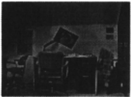
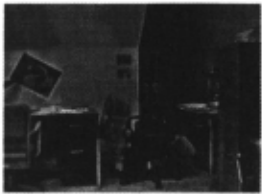
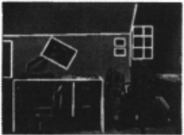
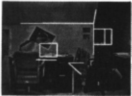
Another set of images was taken in a corridor. Here, because of the deep structure of the corridor, perspective distortions are noticeable. Nevertheless, the alignment results still demonstrate an accurate match in large por tions of the image. Figure 3 shows two model views of the corridor . Figure 4 (left) shows an overlay of a linear combination of the model views with an image of the corridor. It can be seen that the parts that are rela tively distant align perfectly. Figure 4 (right) shows the matching of the corridor model with an image obtained by a relatively large motion (about half of the corridor length) . Because of perspective distortions the relatively near features no longer align (e.g., the near door edges) . The relatively far edges, however, still match.
The experimental results demonstrate that the method achieves accurate localization in many cases.
7 Conclusions
An approach for homing based on localization and posi tioning was introduced. The approach is based on rep resenting the scene as a set of 2D views and predicting the appearance of novel views by linear combinations of the model views. The presented method proceeds in two steps. In the first step the robot attempts to recog nize the environment, and in the second step the robot navigates within the recognized environment toward the target location. Two methods for directing the robot to the target position were proposed. The first approach is based on recovering the exact coordinates of the robot in its environment . Homing is carried out as a direct result of this recovery. The second approach uses a predeter mined homing pattern to execute a simpler algorithm for the process. At each stage the direction to the target is computed directly from the image. Knowledge of the transformation between the model views is not required in this approach.
The method presented in this paper has several advantages over existing methods. It uses relatively rich representations; the representations are 2D rather than 3D, and localization can be done from a single 2D view only. The same basic method is used in both the local ization and positioning problems. Future work includes experiment the full homing process, handling the prob lem of acquisition and maintenance of models, develop ing efficient and robust algorithms for solving the aspects of the correspondence problem needed for this task, and building maps using visual input .
@inproceedings{ijcai1993p220,
  title     = {Homing Using Combinations of Model Views},
  author    = {Basri, Ronen and Rivlin, Ehud},
  booktitle = {Proceedings of the Thirteenth International Joint Conference on
               Artificial Intelligence, {IJCAI-93}},
  publisher = {International Joint Conferences on Artificial Intelligence},
  editor    = {Ruzena Bajcsy},
  pages     = {1586--1590},
  year      = {1993},
  note      = {Robotics and Vision},
  url       = {https://ijcai.org/proceedings/1993/220},
}
TY - CPAPER TI - Homing Using Combinations of Model Views AU - Basri, Ronen AU - Rivlin, Ehud T2 - Proceedings of the Thirteenth International Joint Conference on Artificial Intelligence, IJCAI-93 PB - International Joint Conferences on Artificial Intelligence PY - 1993 SP - 1586 EP - 1590 UR - https://ijcai.org/proceedings/1993/220 ER -Copied
Machine-readable versions of this paper, for tools and AI agents:





