
TINA: The Sheffeild AIVRU Vision System
Proceedings of the Tenth International Joint Conference on Artificial Intelligence. Robotics. Pages 1138-1143.
© 1987 International Joint Conferences on Artificial Intelligence
Abstract
We describe the Sheffield AIVRU 3D vision system for robotics. The system currently supports model based object recognition and location; its potential for robotics applications is demonstrated by its guidance of a UMI robot arm in a pick and place task. The system comprises: / 1) The recovery of a sparse depth map using edge based passive stereo triangulation. 2) The grouping, description and segmentation of edge segments to recover a 3D description of the scene geometry in terms of straight lines and circular arcs. 3) The statistical combination of 3D descriptions for the purpose of object model creation from multiple stereo views, and the propagation of constraints for within view refinement. 4) The matching of 3D wireframe models to 3D scene descriptions, to recover an initial estimate of their position and orientation.
- Arnold R. D. and T. 0 . Binford (1980) Geometric con- straints in stereo vision, Soc. Photo-Optical Instr. Engineers, 238, 281-292.
- Bolles R.C., P. Horaud and M.J. Hannah (1983), 3DPO: A three dimensional part orientation system, Proc. IJCAI 8, Katlshrue, West Germany, 116-120. IJCAI
- Bowen J.B. and J.E.W. Mayhew (1986), Consistency maintenance in the REV graph environment, Alvey Computer Vision and Image Interpretation Meeting, University of Bristol, AIVRU Memo 20, and Image and Vision Computing (submitted).
- Burt P. and B. Julesz (1980), Modifications of the classi- cal notion of panum's fusional area, Perception 9, 671-682.
- Canny J.F. (1983), Finding edges and lines in images, MIT AI memo, 720, 1983.
- DeKleer J. (1984), Choices without backtracking, Proc, National Conference on Artificial Intelligence,
- Doyle J. (1979), A truth maintenance system, Artificial Intelligence 12, 231-272.
- Durrant-Whyte H.F. (1985), Consistent integration and propagation of disparate sensor observations, Thesis, University of Pennsylvania.
- Faugeras O.D., M. Hebert, J. Ponce and E. Pauchon (1984 ), Object representation, identification, and positioning from range data, Proc. 1st Int. Symp. on Robotics Res, J.M. Brady and R. Paul (eds), MIT Press, 425-446.
- Faugeras O.D. and M. Hebert (1985), The representation, recognition and positioning of 3D shapes from range data, Int. J. Robotics Res
- Faugeras O.D., N. Ayache and B. Faverjon (1986), Build- ing visual maps by combining noisy stereo measure- ments, IEEE Robotics conference, San Francisco.
- Grimson W.E.L. and T. Lozano-Perez (1984), Model based recognition from sparse range or tactile data, Int. J. Robotics Res. 3(3): 3-35.
- Grimson W.E.L. and T. Lozano-Perez (1985), Recogni- tion and localisation of overlapping parts from sparse data in two and three dimensions, Proc IEEE Int. Conf on Robotics and Automation, Silver Spring: IEEE Computer Society Press, 61-66.
- Grimson W.E.L. and T. Lozano-Perez (1985), Search and sensing strategies for recognition and localization of two and three dimensional objects, Proc. Third Int. Symp. on Robotics Res.
- Herman M. (1985), Representation and incremental con- struction of a three-dimensional scene model, CMU- CS-85-103, Dept. of Computer Science, Carnegie- Mellon University.
- Pollard S.B., J.E.W. Mayhew and J.P. Frisby (1985), PMF: a stereo correspondence algorithm using a disparity gradient limit, Perception, 14, 449-470.
- Pollard S.B., J. Porrill, J.E.W. Mayhew and J.P. Frisby (1985), Disparity gradient, Lipschitz continuity and computing binocular correspondences, Proc. Third Int. Symp. , on Robotics Res. 1144
- ROBOTICS
- Pollard S.B., J.Porrill, J.E.W. Mayhew and J.P. Frisby (1986), matching geometrical descriptions in 3- space, Alvey Computer Vision and Image Interpreta- tion Meeting, Bristol, AIVRU Memo 022 and Image and Vision Computing (in press).
- Pollard S.B. (1985), Identifying Correspondences in bino- cular stereo, unpublished Phd thesis, Dept of Psychology, University of Sheffield.
- Pollard S.B. and J. Porill (1986), Using camera calibra- tion techniques to obtain a viewer centred coordinate frame, AIVRU Lab Memo 026, University of Sheffield.
- Porrill J. (1985) Notes on: the role of the disparity gra- dient in stereo vision, AIVRU Lab Memo 009, University of Sheffield.
- Porrill J., T. P. Pridmore, J. E. W. Mayhew and Frisby, J. P. (1986a) Fitting planes, lines and circles to stereo disparity data, AIVRU memo017 Porrill J., S.B. Pollard and J.E.W Mayhew (1986b), The optimal combination of multiple sensors including stereo vision, Alvey Computer Vision and Image Interpretation Meeting, Bristol, AIVRU Memo 25 and Image and Vision Computing (in press).
- Pridmore T.P., J.E.W. Mayhew and J.P. Frisby (1985), Production rules for grouping edge-based disparity Data, Alvey Vision Conference, University of Sussex, and AIVRU memo 015, University of Sheffield.
- Pridmore T.P. (1987), Forthcoming Phd Thesis, Univer- sity of Sheffield.
- Pridmore T.P., J. Porrill and J.E.W. Mayhew (1986), Seg- mentation and description of binocularly viewed contours, Alvey Computer Vision and Image Interpretation Meeting, University of Bristol, and Image and Vision Computing (in press).
- Trivedi H.P. and S.A. Lloyd (1985), The role of disparity gradient in stereo vision, Comp. Sys. Memo 165, GEC Hirst Research Centre, Wembley, England.
- Tsai R.Y. (1986), An efficient and accurate camera cali- bration technique for 3D machine vision, Proc IEEE CVPR 86, 364-374.
References were extracted automatically from the PDF and may contain errors.
Full text extracted automatically from the PDF; figures, tables and equations may differ. The PDF is the version of record.
Introduction.
The following is a brief description of the syste-;n:--- Edge based binocular stereo is used to recover a depth map of the scene from which a geometrical description comprising straight lines and circular arcs is computed. Scene to scene matching and statistical combination allows multiple stereo views to be combined into more complete scene descriptions with obvious application to autonomous navigation and path planning. Here we show how a number of views of an object can be integrated to form a useful visual model; which may subsequently be used to identify the object in a cluttered scene. The resulting position and attitude information is used to guide the robot arm. Figure 1 illustrates the system iri - operation.
The system is a continuing research project: the scene description is currently being augmented with sur: face geometry and topological information. We are also exploring the use of predictive feed forward to quicken the stereo algorithm. The remainder of the paper will---_
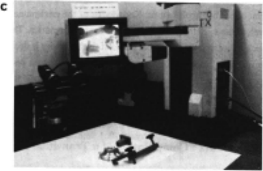
Figure 1. A visually guided robot arm.
Figures (a), (b) and (c) illustrate our visual system at work., A pair of Panasonic WV -COSO CCO cameras are mounted on an adjustable stereo rig. Here they are positioned with optical centers approximately 15cm apart with asymmetric convergent gaze of approximately 16 degrees verged upon a robot workspace some 50cm distant. The 28mm Olympus lens (with effective focal length of approximately 18.5mrn) subtends a visual angle of about 27 degrees. The system is able to identify and accurately locate a modelled object in the cluttered scene. This information is used to compute a grasp plan for the known object (which is precompiled with respect to one comer ofi the object which acts as its coordi nate frame). The UMI robot which is at a predetermined position with respect to the viewer centered coordinates of the visual sys tem is able to pick up the object.
- ·
describe the modules comprising the system in more detail.
PMF: The recovery of a depth map.
The basis is a fairly complete implementation of a single scale Canny edge operator [Canny 1983] incor porating sub pixel acuity (achieved through quadratic interpolation of the peak) and thresholding with hysteresis
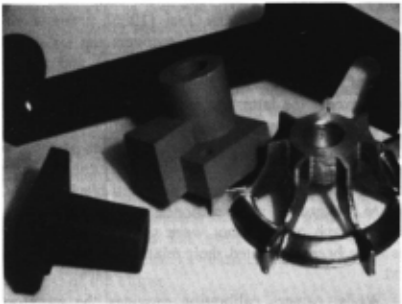
The images are 2S6x256 with 8 bit grey level resolution. In the camera calibration stage, a planar tile containing 16 squares equally spaced in a square grid was accurately placed in the workspace at a position specified with respect to the robot coordinate system such that the orientation of the grid corresponded to the XY axes. The position of the comers on the calibration stimulus were measured to within 15 microns using a Steko 1818 stereo comparator. Tsai's calibration method was used to calibrate each camera separately. We have found errors of the same order as Tsai reported and sufficient for the purposes of stereo matching. The camera attitudes are used to transform the edge data into parallel camera geometry to facilitate the stereo matching process. To recover the world to camera transform the calibration images are themselves used as input to the system, eg are stereoscopically fused and the geometrical description of the edges and vertices of the squares statistically combined. The best fitting plane, the directions of the orien tations of the lines of the grid corresponding to the XY axes, and the point of their intersection gives the direction cosines and position of the origin of the robot coordinate system in the camera coordinate system. The use of the geometrical descriptions recovered from stereo as feedback to iterate over the estimates of the camera parameters is a project for the future.
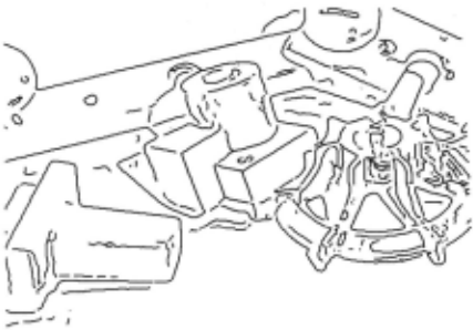
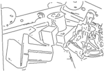
A single scale Canny operator with sigma 1 pixel is used. The non maxima suppression which employs quadratic interpolation gives a resolution of 0.1 of a pixel (though dependent to some extent upon the structure of the image). After thresholding with hysteresis (currently non adaptive), the edge segments are rectified so as to present parallel camera geometry to the stereo matching process. This also changes the location of the centre of the image appropriately, allows for the aspect ratio of the CCD array (fixing the vertical and stretching the horizontal) and adjusts the focal lengths to be consistent between views.
applied to two images obtained from CCD cameras. The two edge maps are then transformed into a parallel cam era geometry and stereoscopically combined (see figures 2, 3 and 4). The PMF stereo algorithm, described in more detail elsewhere [Pollard et al 1985; Pollard 1985], uses the disparity gradient constraint to solve the stereo correspondence problem. The parallel camera geometry allows potential matches to be restricted to corresponding rasters. Initial matches are further restricted to edge seg-
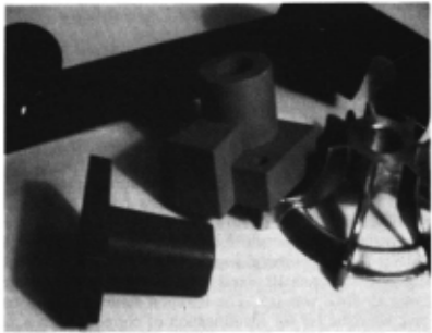
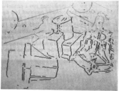
Figure 4. The depth map.
The output of the PMF stereo-algorithm display~d (~th respect to the left image) with disparities coded by mtens1ty (near-dark far-liSttt). The total range of disp~ties in the ~ne was approximately 55 pixels from a searc~ Window. of~ ptx els. PMF is a neighbourhood support algonthm and m this case the neighbourhood was 10 pixels radius. The disparity gradient parameter to PMF was 0.5. The iteration strategy used a con servative heuristic for the identification of correct matches, and their scores were frozen. This effectively removes them from succeeding iterations and reduces the cOJ_nputati~nal e:ost of the algorithm as it converges to the solutton. 5 1teranons were sufficient.
ments of the same contrast polarity and of roughly similar orientations (determined by the choice of a disparity gra dient limit). Matches for a neighbouring point may sup port a candidate match provided the disparity gradient between the two does not exceed a particular threshold. Essentially, the strategy is for each point to choose from among its candidate matches the one best supported by its neighbours.
The disparity gradient limit provides a parameter for controlling the disambiguating power of the algorithm. The theoretical maximum disparity gradient is 2.0 (along the epipolars), but at such a value the disambiguating power of the constraint is negligible. False matches fre quently receive as much support as their correct counter parts. However, as the limit is reduced the effectiveness of the algorithm increases and below 1.0 (a value pro posed as the psychophysical maximum disparity gradient by Burt and Julesz [1980]), we typically find that more than 90% of the matches are assigned correctly on a sin gle pass of the algorithm. The reduction of the threshold to a value below the theoretical limit has little overhead in reduction of the complexity of the surfaces that can be fused until it is reduced close to the other end of the scale (a disparity gradient of 0.0 corresponds to fronto-parallel surfaces). In fact we find that a threshold disparity gra dient of 0.5 is very powerful constraint for which less than 7% of surfaces (assuming uniform distribution over the gaussian sphere: following Arnold and Binford
[1980]) project with a maximum disparity gradie~t greater than 0.5 when the viewing distance is four tlmes the interocular distance. With greater viewing . distances, the proportion is even lower.
It has been shown [Trivedi and Lloyd 1985; Porrill 1985], that enforcing a disparity gradient ensures Lipschitz continuity on the disparity map. Such con tinuity is more general than and subsumes the more usual use of continuity assumptions in stereo.
The method used to calibrate the stereo cameras was based on that described by Tsai [1986] (using a single plane calibration target) which recovers the six extrinsic parameters (3 translation and 3 rotation) and 0-e focal length of each camera. This method has the advantage that all except the latter are measured in a fashion that is independent of any radial lens distortion that may be present The image origin, and aspect ratios of each cam era had been recovered previously. The calibration target which was a tile of accurately measured black squares on a white background was positioned at a known location in the XY plane of the robot work space. After both cam eras have been calibrated th~ir relative geometry is calcu lated.
Whilst camera calibration provides the transforma tion from the viewer/camera to the world/robot coordinate spaces we have found it more accurate to recover the position of the world coordinate frame d~ectly . . ~ter~o matching of the calibration stimulus allows 1ts pos1tton m space to be determined. A geometrical d~scription of ~e position -and orientation of the of the caltbrauon target 1s obtained by statistically combining the stereo geometry of the edge descriptions and vertices. The process is described in Pollard and Porrill [1986].
GDB: The recovery of the geometric descriptive base.
In this section we briefly report the methods for seg menting and describing the edge based depth map to recover the 3D geometry of the scene in terms of straight lines and circular arcs. A complete description of the pro cess can be found in Pridmore et al [1986] and Porrill et al [1986a].
The core process is an algorithm (GDF) which recursively attempts to describe, then smooth and seg ment, linked edge segments recovered from the stereo depth map. GDF is handed a list of edge elements by CONNECT [Pridmore et al 1985]. Orthogonal regression is used to classify the input string as a straight line, plane or space curve. If the edge list is not a statistically satis factory straight line but does form an acceptable plane curve, the algorithm attempts to fit a circle. If this fails , the curve is smoothed and segmented at the extrema of curvature and curvature difference. The algorithm is then applied recursively to the segmented parts of the curve.
Some subtlety is required when computing geometri cal descriptions of stereo acquired data. This arises in part from the transformation between the geometry in disparity coordinates and the camera/world coordinates. The former is in a basis defined by the X coordinates in the left and right images and the common vertical Y coordinate, the latter, for practical considerations (eg there is no corresponding average or cyclopean image), is with respect to the left imaging device, the optical centre of the camera being at (0,0,0) and the centre of the image is at (O,O,f) where f is the focal length of the camera. While the transformation between disparity space and the world is projective, and hence preserves lines and planes, circles in the world have a less simple description in disparity space. The strategy employed to deal with cir cles is basically as follows: given a string of edge seg ments in disparity space, our program will only attempt to fit a circle if it has already passed the test for planarity, and the string is then replaced by its projection into this plane. Three well chosen points are projected into the world/camera coordinate frame and a circle hypothesised, which then predicts an ellipse lying in the plane in dispar ity space. The mean square errors of the points from this ellipse combined with those from the plane provide a measure of the goodness of fit. In practice, rather than change coordinates to work in the plane of the ellipse, we work entirely in the left eye's image, but change the metric so that it measures distances as they would be in the plane of the ellipse.
Typically, stereo depth data are not complete; some sections of continuous edge segments in the left image may not be matched in the right due to image noise or partial occlusion. Furthermore disparity values tend to be erroneous for extended horizontal or near horizontal seg ments of curves. It is well known that the stereo data associated with horizontal edge segments is very unreli able, though of course the image plane information is no less usable than for the other orientations. Our solution to these problems is to use 3D descriptions to predict 2D data. Residual components derived from reliable 3D data
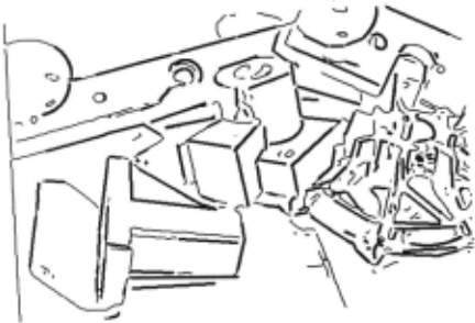
The thin lines depict connected edge segments to which either no description has been ascribed because they were too short, or because they are present only in the left eyes image and only a 20 description was possible. The thicker lines dep ict the connected edge segments for which a 3D geometrical description has been computed. Before segmentation each edge list was smoothed by diffusion (see Porrill [1986]) approxi mately equal to a gaussian of sigma 2.5.
and the image projection of unreliable or unmatched (2D) edges are then statistically combined and tested for accep tance. By this method we obtain a more complete 2D and 3D geometrical description of the scene from the left eyes view than if we used only the stereo data. Figure 5 illustrates the GDB description of our scene.
Evaluation of · the geometrical accuracy of the descriptions returned by the GDF has employed both natural and CAD graphics generated images. The latter were subject to quantisation error and noise due to the illumination model but had near perfect camera geometry; they were thus used to provide the control condition, ena bling us to decouple the errors due to the camera calibra tion stage of the process. A full description of the experi ments are to be found in Pridmore [1987], suffice it to say that we find that typical errors for the orientation of lines is less than a degree, and for the normals of circu lar arcs subtending more than a radian, the errors are less than 3 degrees in the CAD generated images and only about twice that for images acquired from natural scene. The positional accuracy of features and curvature segmen tation points has also been evaluated, errors are typically of the order of a few millimetres which maybe argues well for the adequacy of Tsai's camera calibration method more than anything else.
SMM: The Scene and Model Matcher.
The matching algorithm (see Pollard et al [1986] for details), which can be used for scene to scene and model to scene matching, exploits ideas from several sources: the use of a pairwise geometrical relationships table as the object model from Grimson and Lozano-Perez [1984; 1985], the least squares computation of transformations by exploiting the quaternion representation for rotations from Faugeraus et al [1984; 1985], and the use of focus features from Bolles et al [1983]. We like to think that the whole is greater than the sum of its parts!
The matching strategy proceeds as follows:
- a focus feature is chosen from the model;
- the S closest salient features are identified (currently salient means lines with length greater than L);
- potential matches for the focus feature are selected;
- consistent matches, in terms of a number of pairwise geometrical relationships, for each of the neighbour ing features are located;
- the set of matches (including the set of focus features) is searched for maximally consistent cliques of cardinality at least C, each of these can be thought of as an implicit transformation.
- synonymous cliques (that represent the same implicit transformation) are merged and then each clique is extended by adding new matches for all other lines in the scene if they are consistent with each of the matches in the clique. Rare inconsistency amongst an extended clique is dealt with by a final economi cal tree search.
- extended cliques are ranked on the basis of the number and length of their members.
- the transformation implicitly defined by the clique is recovered using the method described by Faugeras et al [1984].
The use of the parameters S (the neighbours of the focus feature), and C (the minimum subset of S ) are powerful search pruning heuristics that are obviously model dependent. Work is currently in hand to extend the matcher with a richer semantics of features and their pairwise geometrical relationships, and also to exploit negative or incompatible information in order to reduce the likelihood of false positive matches.
TIED: the integration of edge descriptions.
The geometrical information recovered from the stereo system described above is uncertain and error prone, however the errors are highly anisotropic, being much greater in depth than in the image plane. This anisotropy can be exploited if information from different but approximately known positions is available, as the statistical combination of the data from the two viewpoints provides improved location in depth. From a single stereo view the uncertainity can only be improved by exploiting geometrical constraints. A method for the optimal combination of geometry from multiple sensors based on the work of Faugeras et al [1986] and Durrant Whyte [1985] has been developed (for details see Porrill et. al. [1986b]), and extended to deal both with the specific geometrical primitives recovered by the GDF and the enforcing of constraints between them. The method is used in the application being described to integrate the edge geometry from multiple views to create the object model (see figure 6), and to obtain the statistically optimum estimate of the position and direction cosines of the target object coordinate frame after the matching stage has been completed. The latter is done by enforcing the constraints that the axes of the coordinate frame are paral lel to all the lines they should be, that they are mutually perpendicular, and intersect at a single point The result of the application of this stage of the process is the position and attitude of the object in the world coordinates. Figure 7 illustrates the SMM matching the compiled visual model in the scene. The information provided by match ing gives the RHS of the inverse kinematics equation which must be solved if our manipulator is to grasp the object (see figure 8).
REV: the regions, edges, vertices graph.
One may regard the system as generating a sequence of representations each spatially registered with respect to a coordinate system based on the left eye: image, edge map, depth map and geometrical description. In the initial stages of processing a pass oriented approach may be appropriate but we consider that it is desirable to provide easy and convenient access between the representations at a higher level of processing. The REV graph is an environment, built in Franz Lisp, in
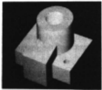
a
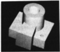
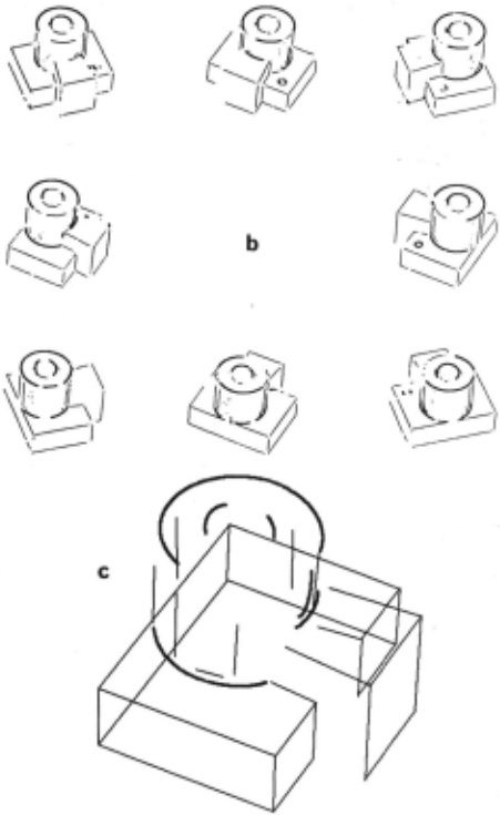
Figure (a) is a pair of stereo images produced by a ver sion of the mM WINSOM CSG body modeler. It depicts the object to be modelled. To ensure a description of the model suitable for visual recognition and to allow greater generality (the same approach has been successfully applied to natural images of a real object) we combine geometrical data from multiple views of the object to produce a primitive visual model of it Figure (b) illustrates the 3D data extracted from eight views of the object. Their combination is achieved by incrementally matching each view to the next. Between each view the model is updated, novel features added and statistical estimation theory used to enforce consistency amongst them (eg. making near parallel and near perpendicular lines truely so). Finally only line features that have been identified in a more than a single view appear in the final visual model (see (c)).
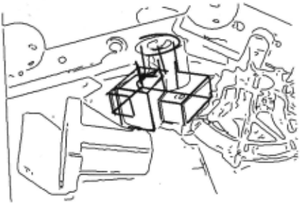
Figure 7. Object location:
The dark lines depict the projection of the object model into the scene geometry after being transformed by the rota tion and translation produced by the matching process (SMM) and the geometry integration process (TIED). The recovery of the object to scene transformation has two stages, they are as follows: first the matcher SMM locates the object model in the scene and recovers a sub-optimum estimate of the rotation and translation. The process is suboptimal because it does not take account of the anisotropies in the errors in the geometry of the matched edge features, and furthermore sequences the problem by first solving for the rotation and then using the rotation to calculate .the translation. Notwithstanding these weaknesses, it is an adequate starting point for the second process which is a linearised recursive solution to the optimal weighted least squares integration of the geometry (TIED), which delivers the corrected transformation. To give some idea of the scale of the matching search problem, the object model contains 41 features and the scene contains 423. Some 15 model focus features, chosen on the basis of length, resulted in the expan sion of only 37 local cliques. The latter were required to be of magnitude at least C-4 from S-7 neighbouring features. The largest clique found by the matcher contained 14 matched lines.
which the lower level representations are all indexed in the same co-ordinate system. On top of this a number of tools have been and are being written for use in the development of higher level processes which we envisage overlaying the geometrical frame with surface and topo logical information. Such processes will employ both qualitative and quantitative geometrical reasoning heuris tics. In order to aid debugging by keeping a history of reasoning, and increase search efficiency by avoiding backtracking, the REV graph contains a consistency maintenance system (CMS), to which any processes may be easily interfaced. The CMS is our implementation of most of the good ideas in Doyle [1979] and DeKleer [1984] augmented with some our own. The importance of truth mamtenance in building geometrical models of objects was originally highlighted by Hermann [1985]. Details of the REV graph and CMS implementation may be found in Bowen [1986].
Conclusions
We demonstrate the ability of our system to support visual guided pick and place in a visually cluttered but, in
a
b
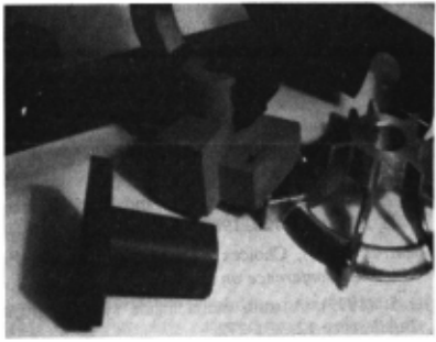
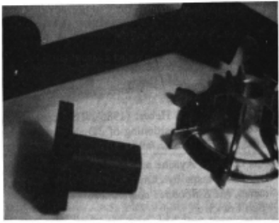
Figure 8. Closing the loop.
Figures (a) and (b) show the arm grasping the object and the scene with the object removed.
terms of trajectory planning, benign manipulator workspace. It is not appropriate at this time to ask how long the visual processing stages of the demonstration take, suffice it to say that they deliver geometrical infor mation of sufficient quality, not only for the task in hand but to serve as a starting point for the development of other visual and geometrical reasoning competences.
Acknowledgements
We gratefully acknowledge Dr Chris Brown for his valuable technical assistance.
@inproceedings{ijcai1987p230,
  title     = {TINA: The Sheffeild AIVRU Vision System},
  author    = {Porrill, John and Pollard, Stephen and Pridmore, Tony P. and Bowen, Jonathan B. and Mayhew, John E. W. and Frisby, John P.},
  booktitle = {Proceedings of the Tenth International Joint Conference on
               Artificial Intelligence, {IJCAI-87}},
  publisher = {International Joint Conferences on Artificial Intelligence},
  editor    = {John McDermott},
  pages     = {1138--1143},
  year      = {1987},
  note      = {Robotics},
  url       = {https://ijcai.org/proceedings/1987/230},
}
TY - CPAPER TI - TINA: The Sheffeild AIVRU Vision System AU - Porrill, John AU - Pollard, Stephen AU - Pridmore, Tony P. AU - Bowen, Jonathan B. AU - Mayhew, John E. W. AU - Frisby, John P. T2 - Proceedings of the Tenth International Joint Conference on Artificial Intelligence, IJCAI-87 PB - International Joint Conferences on Artificial Intelligence PY - 1987 SP - 1138 EP - 1143 UR - https://ijcai.org/proceedings/1987/230 ER -Copied
Machine-readable versions of this paper, for tools and AI agents:





