
Determining Cylindrical Shape from Contour and Shading
Proceedings of the Tenth International Joint Conference on Artificial Intelligence. Perception. Pages 797-799.
© 1987 International Joint Conferences on Artificial Intelligence
Abstract
This paper presents an algorithm for reconstructing the shape of a cylindrical object from contour and shading without knowing the surface albedo of the object or the lightiflg conditions of the scene. The input image is segmented into spherical, cylindrical, or planar surfaces by analyzing local shading. The cylindrical surface is characterized by the direction of the generating lines, determined from spatial derivatives in the image. The brightest generating line has strong constraints on the shading analysis on the cylindrical surface and leads to a simplification of the equation which represents the relation between the contour shape and the shading. Although there remains one degree of freedom between the surface normal of the base plane and the slant angle of the generating line, we can uniquely recover the cylindrical shape from this solution (up to reflection). Experimental results for synthetic image are shown.
- Brady, M. "Computational approaches ' to image under- standing," Computing SuMJe'V•, 14 (1982) 4-71.
- Marr, D. Vision: A Computational Investigation into the Human Representation and Processing of Visual Informa- tion, W. H. Freeman & Co., San Francisco, 1982.
- Horn, B. K. P . "Obtaining shape from shading informa- tion," Chapter 4 in The Psychology of Computer Vision, P. H. Winston, ed., McGraw-Hill Book Co., New York, pp.ll5-155, 1975.
- Woodham, R. J. "A cooperative algorithm for determin- ing surface orientation from a single view," In proc. /JCA/-77. 1977, pp.635-641. IJCAI
- Pentland, A. P . "Local shading analysis," IEEE Trans. PAM/. 6 (1984) 170-187.
- Mackworth, A. K. "Interpreting pictures of polyhedral scenes," Artificial Intelligence 4 (1973) 121-137. IJCAI
- Huffman, D. A. "A duality concept for the analysis of polyhedral scenes," Machine Intelligence, E. W. Elcock & D. Michie, eds., Ellis Horwood, Chichester, pp.279-311, 1977.
- Sugihara, K. "An algebraic approach to shape-from image problems," Artificial Intelligence 23 (1984) 59-95.
- Barrow, H. G. and J. M. Tenebaum, "Interpreting line drawings as three-dimensional surfaces," Artificial Intelli- gence 17 (1981) 249-261.
- Marr, D. "Analysis of occluding contour," Philosophical Trans. of the Royal Society of London B, 275 (1977) 483- 524.
- Brady, M. and A. Yuille, "An extremum principle for shape from contour," IEEE Tram. PAM/. 6 (1984) 288- 301. IJCAI
- Horn, B. K . P . "Understanding image intensities," Artificial Intelligence 8 (1977) 201-231.
- Ikeuchi, I. and B. K. P. Horn, "Numerical shape from shading and occluding boundaries," Artificial Intelligence 17 (1981) 141-184.
- Binford, T . 0. "Visual perception by computer," IEEE Conference on Systems and Controls, Miami, FL, December 1971.
- Nevatia, R. and T. 0 . Binford, "Description and recogni- tion of complex curved objects," Artificial Intelligence 8 ( 1977) 77-98.
- Rao. K. and R . Nevatia, "Generalized cone description from sparse 3-d data," In proc. CVPR86, 1986, pp.256- 263.
- Shafer, S. A. "Shadow geometry and occluding contours of generalized cylinders," Tech. Report CS-83-131, Carnegie-Mellon University, May 1983.
- Asada, M. and S. Tsuji, "Inferring motion of cylindrical object from shading," In proc . OVPR-89, 1983, pp.240- 245.
- Asada, M. and S. Tsuji, " Inferring motion of cylindrical object from shape information," In proc. /JCA/-89, 1983, pp.1032-1034. IJCAI
- Brooks, M. J. and B. K . P . Horn, "Shape and source from shading," Proc. In proc. /JCA/-85, 1985, pp .932-936. IJCAI
References were extracted automatically from the PDF and may contain errors.
Full text extracted automatically from the PDF; figures, tables and equations may differ. The PDF is the version of record.
1. INTRODUCTION
Recent studies on computer vision have exploited many methods for interpreting a brightness pattern in an image as a shape in 3-D space using physical constraints on the light source, object class, surface properties of the object and multi ple views (Brady 1975). Especially, contour and shading in the image have a very important role in recovering surface shape in both computer vision and human perception (Marr 1982). Shape from shading methods obtain surface properties by exploiting photometric constraints on the image formation pro cess (Horn 1975, Woodham 1977). The difficulty in these methods is to characterize the lighting geometry, because most of them cannot recover the surface shape unless the lighting conditions are given . Although Pentland (Pentland 1984) has tried to extract information on shape locally without knowing the lighting conditions, his method requires strong assump tions, e.g. that the surface is spherical. Interpretation of line drawings has been one focal point of vision work, and there are successful results in the polyhedral world (Mackworth 1973, Huffman 1977 and Sugihara 1984). Outside this world, only qualitative description is obtained (Barrow and Tene baum 1981, Marr 1977), such as extremal boundaries and sur face discontinuities, or a strong assumption is necessary to recover the surface orientation, e.g. the extremum principle (Brady and Yuille 1984). The first quantitative approach to recovering surface shape from contour and shading was developed by Horn (Horn 1977). In his method, the reflectance map is effectively used to infer the surface normals of the planes of a block in gradient space. Also lkeuchi and Horn (Ikeuchi and Horn 1981) used the occluding boundaries as boundary conditions on their relaxation method to infer the surface structure. Both methods, however, assume that the the lighting conditions and the surface albedo are known.
This work was supported by the Defense Advanced Research Projects Agency and the U.S. Army Center for Night Vision and Electro-Optics under Grant DAAB07-85-K-F073.
·Permanent address : Department of Control Engineering, Osaka University, Toyonaka, Osaka 560, Japan
In those methods, the surface type is planar (in the polyhedral world) or doubly curved (for shading analysis). Between them is the class of objects that have singly curved surfaces. The most representative object in this class is a cylindrical object which can be often seen in daily life. Cylindrical models have been popular for describing many kinds of objects in terms of generalized cylinders since Binford (Binford 1971) introduced them as a useful method of volume description for 3-D objects. Although several papers have been published which attempt to describe cylindrical shape parame ters from range data (Nevatia and Binford 1977, Rao and Nevatia 1986) or which examine geometrical properties of gen eralized cylinders with shadows and occluding boundaries (Shafer 1983), there are few papers dealing with the problem of reconstructing cylindrical shapes from images. Asada et al. (Asada and Tsuji 1983a,b) proposed two approaches to recon structing a cylindrical shape from the viewpoint of dynamic scene analysis. One approach is to analyze shading information to obtain the normals of surfaces, which are useful for finding the correspondence of base planes between consecutive frames. Local shading analysis (Pentland 1984) is not applicable to estimating the normal at a point on a cylindrical surface unless the lighting conditions are known. With knowledge of the lighting conditions, the motion between frames can be deter mined by the extended reflectance map method. The other approach is to analyze changes in contour shape between frames. If the base planes of an object are perpendicular to its cylindrical surface, the 3-D geometry of the object can be recovered from two views. The first approach cannot recon struct the cylindrical shape without knowledge of the lighting conditions; the second approach needs two frames and assumes perpendicularity of the base plane to the cylindrical surface.
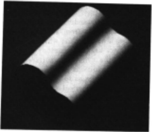
We consider the image understanding problem of infer ring the shape of a cylindrical object from an image such as Figure 1. This paper presents a new method which determines the shape of a cylindrical object using the contour of the base plane and the intensities on the cylindrical surface without knowledge about the lighting conditions of the scene or the albedo. Local shading analysis enables us to segment the input image into planar, cylindrical and spherical surfaces and tells us the direction of the generating line from which the cylindri cal surface is produced. The brightest generating line, like singular points and occluding boundaries which play a impor tant role in shape from shading meth-ods (Ikeuchi and Horn 1981, Brooks and Horn 1985), provides strong constraints on shading analysis on the cylindrical surface and on the relation between the contour shape of the base and the brightness on the cylindrical surface.
The validity of our method is tested using a synthetic image.
2. BASIC ASSUMPTIONS
The computational analyses in this paper are based on the following three assumptions.
(1) The projection from scene to image is orthographic.
(2) The object has cylindrical and planar surfaces.
Here, a cylindrical surface is defined as a surface covered with parallel lines (generating lines) that pass through a closed curve.
(3) The surface is Lambertian and has a constant albedo. It is not necessary that both the planar surface and the cylindrical surface have the same albedo. The distribution of illumination is constant (distant point source illumination).
We can segment an image projected from a scene contain ing unknown shaped objects into spherical, cylindrical, and planar surfaces if (3) is assumed. That is, we can test whether (2) is true or not.
3. SHADING ANALYSIS
3.1 Local Shading Analysis
Pentland presented a computational analysis of local shading without knowledge of lighting conditions. It gives an estimate of surface orientation for an umbilical point (having equal principal curvatures) on a Lambertian surface, and also identifies whether the surface is planar, singly or doubly curved at each point.
We use this algorithm for segmentation of the image to find each surface and to identify shape as spherical, cylindrical, or planar. Figure 1 shows an input image (a 256 by 256 8bit digital image of a cylindrical object synthesized by computer) and Figure 2 is the result of the analysis of Figure 1. From this picture we obtain the information that the object has a cylindrical and a planar surface. Another important feature of the cylindrical surface, the direction of its generating lines in the image, is also obtained .
3.2 Brightness on the Cylindrical Surface
For simplicity and without loss of generality, we can choose the viewer-centered coordinate system W, so that the X-axis is parallel to the generating line in the image (the gen erating line has slant angle u relative to the X-axis in 3-D space) and the Z -axis is parallel to the viewing direction.
First, let us consider the brightness on the cylindrical surface in the cylindrical surface centered coordinate system W, whose X-axis is parallel to the generating line in 3-D space and whose Y-axis is parallel to that of the viewer. centered coordi nate system W, . Figure 3 shows the relation between these two coordinate systems. The observed intensity E, at a point in W, is equal to the observed intensity E, at the same point in W, because we assume a Lambertian surface. E, can be represented by the following equation:
where p is the albedo of the cylindrical surface, I is the inten sity of the illuminant, (p, ,q,) denotes the surfac·e orientation on the cylindrical surface and (p., ,q.,) is the light source direc tion in W, . Since these parameters are defined in W,, the sur face orientation on the cylindrical surface has only one param eter 6 at each point as in Figure 4, that is, p, =0 and q, =tan6. Therefore, eqn (3.1) becomes
where tan(>-)=q., . If we substitute the following equation into eqn (3.2):
then we obtain
This equation tells us the following important facts about the brightness on the cylindrical surface:
- Rather than knowing the actual lighting conditions (the illuminant I and the direction of light source (p" ,q., )), we can always assume normalized lighting conditions where the illuminant is I 1 and the direction of the light source is (O,q., ).
- The brightest intensity on the cylindrical surface Em .. = pi 1 where 9=>-.
- The ratio of the intensity of a point to that of the brightest point (Emu) gives us the cosine of the angle between the sur face normal (9) at the point and the normalized light source direction (>-).
- The intensity on the cylindrical surface gives us no informa
- tion about the slant angle (u) of the generating line.
We call this equation the Brightness Constraint Equation on the cylindrical surface.
-'· CYLINDRICAL SHAPE FROM CONTOUR AND SHADING
4.1 Cylindrical Shape from Contour
A cylindrical shape is characterized by the shape of a cross-section perpendicular to the cylindrical surface, because the normal to the contour of the intersection represents the surface normal on the cylindrical surface, as shown in Figure 4.
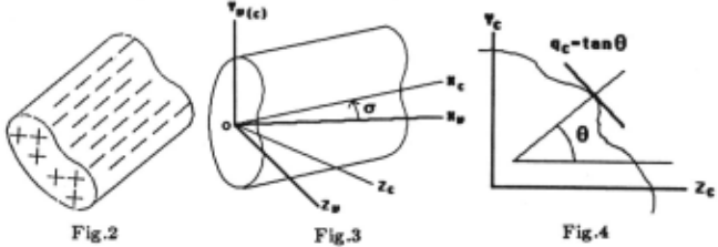
In other words, determining the surface normal on the cylindr ical surface is equivalent to reconstructing the shape of a cross-section perpendicular to the cylindrical surface.
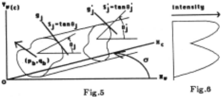
Therefore, let us consider how to recover the shape of the perpendicular cross-section from the contour of the base plane in the image. There are three unknowns, the surface orienta tion of the base plane (p6 ,96} and the slant angle of the gen erating line 17. The shape of the cross-section can be obtained by mapping the contour of the base plane onto a plane perpen dicular to the generating line as shown in Figure 5.
Proposition 1 : The coordinates (i; .!I;) of the contour mapped onto the cross-section are given by the following equa tion:
where (z; ,~oy} denote the coordinates of the base contour in the image plane . .
Proof : Since we assume orthographic projection, the base plane can go through the origin in the viewer coordinate sys tem w ·. Therefore, the coordinates of the base contour in w. are ( z; ,If; ,-p6 z;-96 II;). Rotating these points about the Y -axis by the angle 1T/ 2--17, we obtain eqn {4.1}.
Proposition 2 :Similarly, we obtain the relation between the normals on the contour in the image and those on the cross section as follows:
where i;=tanO'; (shape parameter of the cross-section) and &;=tanfJ; (shape parameter in the image plane) as shown in Figure 5.
·Proof : Since the shape parameters 8 1 and &; are perpendicu lar t? the tangents I; and g1 to the contours (see Figure 5}, we obtam the following equations, in the image plane and on the cross-section, respectively:
and
From these equations, we obtain eqn {4.2}.
In order to determine the cylindrical shape parameter 8 1 1 from. the shape parameter &; in the image plane, we have to obtam three unknowns, the surface orientation of the base plane (P6 ,96) and the slant angle of the generating line (17) . We call eqn (4.2} the Contour Constraint Equation.
4.2 Combining Constraints from Shading and Contour
In order to determine the cylindrical shape, we need to combine the brightness constraint equation (eqn (3.3}} and the contour constraint equation (eqn (4.2}}. From eqn (3.3}, we obtain the following equation:
Also, we obtain the following equation from eqn ( 4.2}:
To combine these equations, we rotate i 1(=tanll'1) about the origin by the angle -}.. ; then we obtain the following equation:
Eqns (4.4} and (4.6} give
where
Dividing eqn (4.7} by cos}.. (~0) leads to .the following equation:
Since eqn (4.8} is a nonlinear equation with four unknowns, p6 ,q6 ,17 and }.., solving this equation analytically seems very difficult. However, we obtain the following proposition using the brightest generating line constraint.
Proposition 3 : Eqn {4.8} represents the conic curves in the following form:
where 0=p6c0517-sinl7, <l>=q6cOSO", A=& 1 -4·, R=&;&/', 0=&f+4·, and &/'is the shape parameter of the brightest gen erating line.
Proof: At the brightest point, R;=O; therefore, we obtain the following equation:
Substituting eqn (4.10} into eqn (4.8} gives eqn (4.9}.
Eqn ( 4.9) suggests the follotving remarks:
- We need at least two points except the brightest point in order to determine 0 and <1>.
- Since this equation is symmetric about the origin, the solu tion {0,<1>} is also symmetric about the origin; that is, if {0,<1>} is a solution then (-0,-<1>} is also a solution. This means that we can interpret the input image in two ways, one as viewing the cylindrical surface from outside and the other as viewing the inside surface of the object as in a cut model. The later is unlikely and is illegal if we assume general position of the viewer.
- *The solution (0,<1>} can uniquely determine the exact shape of the cross-section from eqn (4.1}; however, there remains one degree of freedom among p6 ,q6 and 17.
We call eqn (4.9} the Constraint on Shading and Contour.
5. EXPERIMENTAL RESULTS
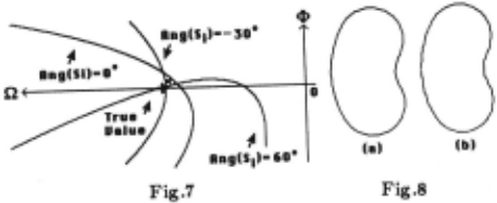
Figure 1 shows a synthetic image (256 by 256 8-bit digital image) of a cylindrical object whose base plane is perpendicu lar to the generating line. The longest diameter of the base is 128 pixels and the length of the generating line is 200 pixels. The incident angle of the normalized light source >- is 38', and the slant angle of the generating line u is 45' ; therefore, p6 =-1 and q6 =0 if we set the X-axis parallel to the generating line in the image plane. Thus, 11=-v'2 and 4>=0. Figure 6 shows the intensity profile of the cylindrical surface; each intensity is quantized into 8-bit gray levels.
Since the solution is symmetric about the origin as described in section 4, we find the solutions in a half space of the entire (11,4>) space, for example, 11:::;0. After finding the solutions in the half space, we decide which is true and which is the reflection of true by recovering the geometrical structure of the base and the cylindrical surface. In the structure of the reflection, the viewer sees the inside surface of the cylindrical object.
In order to determine 11 and 4>, we need at least two points not on the brightest generating line. Each point gives two hyperbolas; therefore, we obtain four intersections as the candidate solutions in the half space when we use only two points on the cylindrical surface. Then, another point is neces sary to obtain the unique solution.
Figure 7 shows three hyperbolas arising from points on a cylindrical surface whose shape parameters are a;=tanO; (0;=7r/3, 0 and -1rj6) and whose intensities are 225, 192 and 44, respectively. In this figure, only one of the two hyperbolas for each point is shown. The intersection points give 11=-1.34 and 4>=0.07. The slight difference between the true and estimated solutions is caused by quantization error. The shape parameter a; in the image plane is calculated by fitting a circular arc to 15 consecutive points along the contour. Sub stituting the obtained solution into eqn (4), we can reconstruct the shape of the cross-section. Figures 8 (a) and (b) show the shape of the cross-section; (a) is for the true shape and (b) is for the estimated shape. The similarity of these shapes indi cates the validity of the method.
6. CONCLUSION
A method which reconstructs a cylindrical shape from the base contour and the brightness on the cylindrical surface without knowledge of the lighting conditions or the surface albedo has been described. The brightest generating line plays a very important role in both the brightness constraint equa tion on the cylindrical surface and the brightness and contour shape constraint equation. In the former, the actual lighting conditions can be transformed into normalized lighting condi tions where the light source direction is parallel to the surface normal on the brightest generating line, and the illuminant intensity times the surface albedo is easily obtained by measuring the intensity on the brightest generating line. In the latter, the nonlinear equation with four unknowns is converted into conic curves involving two unknowns by introducing the brightest generating line constraint.
Although we can uniquely determine the cylindrical shape (up to reflection), there remains one degree of freedom between the surface normal of the base and the slant angle of the gen erating line. If we used other constraints, for example, stereo vision or motion, we would be able to deduce these parame ters. This is a goal of our future research.
@inproceedings{ijcai1987p164,
  title     = {Determining Cylindrical Shape from Contour and Shading},
  author    = {Asada, Minoru},
  booktitle = {Proceedings of the Tenth International Joint Conference on
               Artificial Intelligence, {IJCAI-87}},
  publisher = {International Joint Conferences on Artificial Intelligence},
  editor    = {John McDermott},
  pages     = {797--799},
  year      = {1987},
  note      = {Perception},
  url       = {https://ijcai.org/proceedings/1987/164},
}
TY - CPAPER TI - Determining Cylindrical Shape from Contour and Shading AU - Asada, Minoru T2 - Proceedings of the Tenth International Joint Conference on Artificial Intelligence, IJCAI-87 PB - International Joint Conferences on Artificial Intelligence PY - 1987 SP - 797 EP - 799 UR - https://ijcai.org/proceedings/1987/164 ER -Copied
Machine-readable versions of this paper, for tools and AI agents:





