
A Cooperative Algorithm for Determining Surface Orientation from a Single View
Proceedings of the Fifth International Joint Conference on Artificial Intelligence. Vision. Pages 635-640.
© 1977 International Joint Conferences on Artificial Intelligence
Abstract
Full text extracted automatically from the PDF; figures, tables and equations may differ. The PDF is the version of record.
A COOPERATIVE ALGORITHM FOR DETERMINING SURFACE ORIENTATION FROM A SINGLE VIEW
Robert J. Woodham Artificial Intelligence Laboratory Massachusetts Institute of Technology Cambridge, Massachusetts, 02139
INTRODUCTION
This paper addresses the problem of determining local surface orientation from the Intensity Information contained in a single monocular view. It represents another look at the problem of obtaining shape from shading Information. This problem was first formulated by <Horn 1970> as the solution of first-order non-linear partial differential equations. It was subsequently reformulated by <Horn 1975> to take advantage of the geometric Insight provided by the gradient space approach popularized by <Huffman 1971,1975> and <Mack worth 1973>.
The goal of this work Is to understand how the observed Intensity variation across surfaces of objects forces conclusions about the local topography of those surfaces. The problem Is formulated as a problem In Image analysis. This paper adopts the position that It Is Important to examine ways of squeezing out the last ounce of Information from the Intensity values recorded In an Image before .taking recourse to high-level knowledge.
In order to exploit intensity information, It Is vital to understand how Intensity values arise in an Image. The paper begins by Introducing gradient space and reflectance map techniques. Having developed these tools, the physical constraints imposed by the light source, object surface and viewer geometry are re-examined to recast the <Horn 1975> formulation as a cooperative computation which determines local surface orientation by matching points In an Image to their corresponding points In gradient space. Finally, the method Is illustrated using the simple example of a Lambertian sphere Illuminated by a single distant light source.
GRADIENT SPACE AND THE REFLECTANCE MAP
In order to understand the correspondence between Intensity data and local surface orientation, It Is necessary to relate the geometry of the Image forming process to the photometry of the object being Imaged. The problem of determining local surface orientation from Intensity can be characterized as a mapping:
which assigns to each Image Intensity point I(u,v) a local surface orientation LSO(u,v). In a visual world consisting of opaque smooth objects Immersed In a transparent medium, the mapping T Is well defined since each Image Intensity point I(u,v) arises from a unique object point (which, In turn, defines a unique surface orientation). What Is not obvious, however, Is whether T can be determined from Intensity data alone. The difficulty, of course, Is that T Is not a local operator. In formulating an algorithm for determining local surface orientation from Image Intensity, It will be Important to keep track of how additional physical constraints are used In the computation.
Now, LSO(u,v) Is a tWo-valued function of u and v since two parameters are required to specify an arbitrary orientation In space. One might expect surface orientation to be difficult to represent explicitly. Gradient space is Introduced as ihe appropriate formalism for reasoning about surface orientation.
Gradient space can be derived In several ways. For present purposes, it will be related directly to surface orientation. If the equation of a smooth surface Is given by:
then (oflox,ofloy,-1) defines a local (outward) surface normal. (Throughout this paper, smooth will Interpreted to mean z · f(x,y) has continuous first and second partial derivatives.) Now, let:
so that the local (outward) surface normal becomes (p.q.-1). The quantity (p,q) will be called the gradient and gradient space Is defined to be the two-dimensional space of all such points (p,q).
The fraction of light reflected by a surface In a given direction depends upon the optical properties of the object material, the surface micro-structure and the spatial and spectral distribution of the Incident light. The Important photometric observation underlying this work Is the following: no matter how complex the distribution of incident illumination, for most surfaces, the fraction of the Incident light reflected In a particular direction depends only on the local light source, object surface and viewer geometry. To make this observation more concrete, one can standardize the local representation of the light source, object surface and viewer geometry and tie this representation down to gradient coordinates p and q.
A surface photometric function .(i,e,g) is typically defined In terms of the three angles I, e and g illustrated in figure I. These angles are called, respectively, the incident, emergent and phase angle. Here, the emergent angle e will be referred to as the vtew angle.
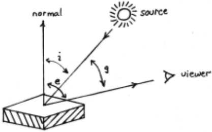
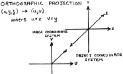
If both the viewing direction and the direction of incident lllumination are known, then expressions for cos(l), cos(e) and cos(g) can be derived In terms of gradient space coordinates p and .q. To simplify matters, consider an image forming system that performs an orthographic projection. The Important simplification inherent in the assumption of an orthographic projection Is that the viewing direction, and hence the phase angle g, Is constant for all Image points (u,v). To further simplify the mathematics, one can align the viewing direction with the negative Z-axis and assume a scaling in U and V that takes object point (x,y,z) to image point (u,v) where u · x and v - y (see figure 2). Under this projection, the use of separate Image coordinates (u,v) Is redundant. Henceforth, image coordinates (x,y) and object coordinates (x,y) will be referred to Interchangeably. With this geometry, object space vector (0,0,-1) points In the direction of the viewer. That Is, the viewer is located at gradient space point (0,0).
Now, for a given distribution of Incident illumination, a given surface-viewer geometry and a given object material, the image Intensity corresponding to a surface point with gradient (p.q) is unique. The Intensities recorded at each (p,q) Is called the reflectance map R(p,q). Reflectance maps can be determined empirically, derived from phenomenological models of surface reflectivity or derived from analytic models of surface micro-structure. Once determined, however, the reflectance map Is independent of the shape of the objects being viewed. It represents explicit knowledge of Intensities that can be recorded from objects made of a given material and viewed under a particular light source and viewer geometry. The reflectance map accounts for the physical Intensities that can be recorded under varying components of diffuse and specular reflection. It does not, of course, account for the human perception of those Intensities. (eg. A local specular component can make an otherwise ·dun· surface appear ·gloss(.)
Consider an Image whose Intensity values I(x,y) have been normalized to equal the reflectance map values at the corresponding gradients (p,q). Then, the following equation describes the image forming process:
This Is the basic equation relating Image intensity to the geometry of the Image forming process. It Is one equation in the two unknowns p and q. Thus, the problem of determining local surface orientation from Intensity becomes the problem of finding the point In gradient space (p.q) corresponding to the Image Intensity point I(x,y).
Now, the simplest case for Incident Illumination Is that of a single distant point source. Choose such a source and place it so that object space vector (p,.q,.-1) points In the direction of the source. That Is, the source Is located at gradient space point (p 8 ,q 8 ). Specifying a single distant point source Is not a fundamental restriction on the development. Non-point sources can be modeled as the superposition of single point sources. The development does, however, assume equal illumination at all surface points. For non-convex surfaces, the reflectance map does not account for the fact that certain surface points can be shadowed with respect to one or more of the sources nor for the fact that certain surface points can receive additional Illumination due to light reflected from other sections of surface (mutual Illumination).
Recall that, object space vector (p,q.-1) is an (outward) normal to the surface point (x,y,z). That is, (p.q) Is the gradient point corresponding to the surface point (x,y,z). Then, using standard vector algebra, the expressions for cos(!), cos(e) and cos(g) become:
Using the above expressions, It Is clear that one can transform an arbitrary surface photometric function .(l.e,g) into a reflectance map R(p,q). By now, It should be clear how points In gradient space correspond to orientations In object space. However, It Is possible to be more explicit about the correspondence between movement In gradient space and changes in local surface orientation.
Using elementary trigonometry, the expression for cos(e) can be rewritten as:
This gives a first useful Interpretation that the inclination of the surface with respect to the viewing direction varies monotonically with the distance from the origin In gradient space. Specifically, the distance from the origin Is the tangent of the angle .between the surface normal and the view vector. As the gradient (p,q) moves away from the origin, the Inclination of the surface with respect to the viewer increases. As the gradient (p.q) moves toward the origin, the Inclination of the surface with respect to the viewer decreases.
Now, the view angle e characterizes one of the two degrees of freedom associated with an arbitrary orientation In space. Note that the locus of points in object space having a constant view angle e defines a right circular cone oriented along the viewing direction. The an~ular position of each gradient (p,q) on the circle p 2 + q 2 · tan (e) defines the direction of steepest descent In Image space along this cone. This gives a second useful Interpretation that the angular position of a point (p.q) In gradient space corresponds to the direction of steepest descent In Image space along the original surface. Rotating object space about the view vector Induces an equal rotation in gradient space.
@inproceedings{ijcai1977p148,
  title     = {A Cooperative Algorithm for Determining Surface Orientation from a Single View},
  author    = {Woodham, Robert J.},
  booktitle = {Proceedings of the Fifth International Joint Conference on
               Artificial Intelligence, {IJCAI-77}},
  publisher = {International Joint Conferences on Artificial Intelligence},
  editor    = {Raj Reddy},
  pages     = {635--640},
  year      = {1977},
  note      = {Vision},
  url       = {https://ijcai.org/proceedings/1977/148},
}
TY - CPAPER TI - A Cooperative Algorithm for Determining Surface Orientation from a Single View AU - Woodham, Robert J. T2 - Proceedings of the Fifth International Joint Conference on Artificial Intelligence, IJCAI-77 PB - International Joint Conferences on Artificial Intelligence PY - 1977 SP - 635 EP - 640 UR - https://ijcai.org/proceedings/1977/148 ER -Copied
Machine-readable versions of this paper, for tools and AI agents:





