
An Integration Tool for Life-Cycle Engineering
Proceedings of the Tenth International Joint Conference on Artificial Intelligence. Knowledge Representation. Pages 592-594.
© 1987 International Joint Conferences on Artificial Intelligence
Abstract
Life-cycle engineering is the integr a ti on of the design process, which addresses primarily the system's performance , with analysis of the design 's other attributes, including reliability, maintainability, lifecycle cost, and manufacturability . The advent of symbolic approaches to design integration reveals the requirement and opportunity of using higher -level analysis to select the optimum design . This opportunity is present only when human interaction is reduced sufficiently to permit several complete design and analysis cycles to take place . We have implemented a generic integration tool that has been demonstrated to significantly shorten the design cycle, and are studying its application to life-cycle engineering. This logic-based tool regards the requested attributes as a set of uninstantiated variables and invokes external computational programs, recursively if necessary, to achieve a proof consisting of the computed variable bindings. Key Words: Software integration, engineering design, expert system.
- Kowalik, J .S .; Chalfan, K.M.; Marcus, R.I.; and Skillman, T.L. "Composite Software Systems," Boeing Computer Services internal working paper, 1987.
- Kowalik, J.S., and Chalfan, K.M. "High Speed Computing and Artificial Intelligence Connection," The International Journal of Supercomputer Applications, to appear in 1987.
- Naft, J., and Pecht, M. "Ramcad for Printed Circuit Board Design," Proceedings of Technical Interchange Meeting, Institute for Defense Analyses, Alexandria, VA, October 21-22, 1986. Chalfan '595
References were extracted automatically from the PDF and may contain errors.
Full text extracted automatically from the PDF; figures, tables and equations may differ. The PDF is the version of record.
I Introduction
In engineering design and analysis, knowledge of how to create the design is fragmented among numerous computational programs. These programs typically perform computer-aided design and other computational functions such as simulation modeling, dynamic analysis, and optimization. The programs are islands of automation within an environment that is not otherwise automated. Design and analysis of the product require that they be integrated as defined by their input and output data relationships. Because of the complexity of the interrelationships among the programs, numerous delays and errors occur during their integration. These delays and errors can increase costs, cause scheduling crises, and reduce design quality. (Kowalik and Chalfan [1987) discuss this problem.) When the desi'gn is complete, it addresses only performance. Usually no feasible alternatives are developed because of the high cost of the design cycle. When subsequent analyses reveal shortcomings in other attributes that may actually have more effect than performance on the life-cycle cost of the product, last-minute changes are made that often unnecessarily compromise performance.
In order to rapidly generate numerous design alternatives, we have formalized in an expert system the problem-solving knowledge required to integrate the components of the design process. The expert system "understands" the objectives of the analyst and executes all programs necessary to produce the desired design. This paper describes the Expert Executive, which we developed for preliminary design and are now applying to electronic circuit design, and describes how this work relates to the broader problem of life-cycle engineering.
II The Integration Problem
For the typical design and analysis problem, there is a set of programs that are logically interrelated by computed data values. This relationship can be represented as a directed graph. In electronic circuit design, as depicted in Figure 1, an electronic comp.uter aided design (ECAD) program typically produces a
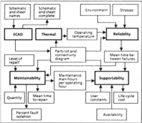
parts list and a connectivity list. The bold rectangles represent computational programs, and the light ones represent input and output variables, as indicated by
Copyright © 1986 The Boeing Company the arrows. The parts and connectivity lists are input to thermal and reliability analysis, maintainability, and life-cycle cost. The involvement of the designer typically ends when the performance of the circuit, as measured by the thermal analysis program, is satisfactory. Subsequent analysis is outside the primary design cycle. Outputs from thermal analysis are input to reliability, and so on.
In preliminary design of aerospace vehicles, four codes form the basis of analysis: wetght, aerodynamics, propulsion, and performance. Figure 2 depicts a typical configuration of these codes. For example, w1 is an output of the weight technology code and also an input to the aero technology code. Some input variables, such as v, are not output by any of the technology codes in the given configuration. They are known as free design parameters. A typical task might
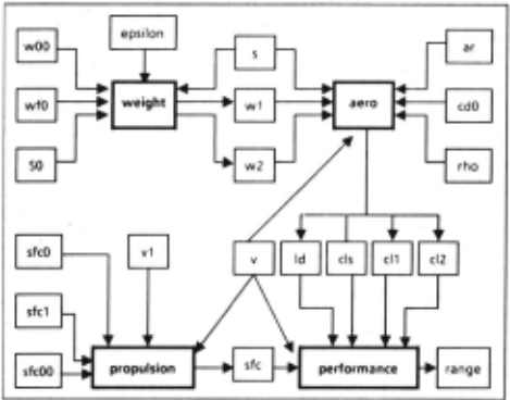
be to compute the range of a vehicle. Since the performance code requires inputs from the propulsion and aero codes, propulsion and aero must be run first. In turn, the weight code must be run before the aero code can be executed. When the range is finally obtained, the cycle begins again, based on perturbations of free design parameters. If a different vehicle type is considered, a different set of technology codes may be applied.
Each program is "owned" and validated by a technology group, such as Weights Technology and Propulsion Technology for preliminary design, or ECAD and Reliability for electronic circuit design. In the absence of an automated integration program, technology groups interact to identify the appropriate technology codes to run, obtain input values from one another, run the codes, and analyze the results. The computed values are manually extracted from code outputs and inserted, possibly erroneously, as input values for other codes. Since the typical design cycle requires several weeks, and multiple design concepts may be generated in parallel, technology analysts may be uncertain which version of which design they are addressing. Because of the time required for the paper output to be analyzed and the appropriate values to be passed to other groups, and the scheduling problems for such a complex activity, often only one or two designs can be constdered. It is then very difficult to justify the selection of one design over all other possible designs. Because of the high cost of the preliminary design process with respect to the quality and quantity of designs produced, the need for an integrated approach to preliminary design has long been recognized within the industry. However, earlier solutions failed due to the complexity of the problem, variability of codes, inflexibility of the procedural control structures embedded in the integration pro~rams, and the administrative difficulties of validating new versions of the integrated codes within the various technology organizations.
III The Expert Executive for Preliminary Design
Symbolic computing presented a new approach to this problem. Kowalik et al. [1987] have described a class of composite software systems that integrate knowledge-based processes and numerical processes into a single unified system. We hypothesized that if the general knowledge of how to run the technology codes and compute the values of design variables could be codified, then the specifics of the problem could be addressed relatively inexpensively and thereby provide a practicable integration capability. To investigate the feasibility of this approach, we developed a preliminary design tool with an "Expert Executive" that contained symbolic knowledge of how to execute a set of computational programs. The Expert Executive assumes the support functions currently assigned to the technologists, thereby freeing them to perform design and analysis. By expediting the computation process, it provides more design alternatives.
The Expert Executive is currently being reimplemented in Quintus Prolog. The current knowledge base, which remains unchanged for all sets of computational programs, contains about 120 propositions . In addition, fact bases contain information about the inputs and outputs for each of the programs to be configured. The size of a fact base depends mostly on the number of inputs and outputs, since each is described by one fact.
The rules provide knowledge about solving a specific, user-defined problem. For example, the Expert Executive has several rules for finding the value of a variable. Variable values are represented as a relation between a variable and its value. The knowledge base contains one such statement, or proposition, for each variable whose value is known through either user input or computation. As additional knowledge is acquired through computation or interaction with the user, additional value-of propositions are asserted into the knowledge base.
The fact base consists of input, output, and script name propositions. Input propositions are in a format that translates to "the first input to the propulsion code is v (velocity)." The sequence number indicates the sequence in which it is read by the computational program. Output propositions are in a similar format, which translates to "the fourth output from the aero code is cl2 (coefficien t-of-li ft-2) ." Script-name propositions provide a relation between the name of the computational program and the path to the script that executes the program.
The Expert Executive uses the following problem solving paradigm: "To run a program, if all the inputs to the program are present, execute the program and return the result. Otherwise find all the required input variables whose values are not known and consult the analyst for starting values. Then, if all the needed inputs are still not present but there is another program, the outputs of which provide the missing mputs, run that program first."
This paradigm is implemented as follows. First there must be a rule for running the selected binary program. This rule may be translated as follows: "If all the values for the program's free design parameters are present, and the computation is performed, and output is obtained, and the output variables are paired with their values, then it is true that the program has been run and the result returned."
Then, for each of the conditions there must be at least one rule with that condition as a conclusion. Such a rule may be translated: "If the program is ready (all its inputs are present in the required sequence), and the script-name is known, and it is executed, and its output variables are paired with the computed values, and the computed values are asserted into the knowledge base, then it is true that results have been computed for the program." In backward chaining to prove this rule true, the numeric computations are performed through a call to a Unix shell. fhis call creates a process executing the named script. (In the original Franz Lisp implementation, this call was provided more generically by the function *process.). This script executes exactly the same copy of the validated program that is executed by the technology groups, thereby ensuring that data are valid and providing access to standalone, commercial software packages. Also, all networking capabilities of the operating system are provided in this way. Standard input and output for the script are temporarily reassigned to Prolog, so that the object program reads from a Prolog write routine, which writes program input values interleaved by carriage returns. Program output is read analogously. When the ports are closed, the process dies.
This compute-result rule may fail because one of the inputs is not known. For this case there is a second rule, which translates: "If the rrogram is not ready to run, and all the parents o the program (those ·programs whose output is input to the program) are found, and each of them is run, then it is true that results have been computed for the program."
Since the rule for running the program requires that all required input values be present, the program may fail to execute on the first attempt. However, the side effects from the first attempt cause the input variables to be bound. On the next attempt, program execution will succeed. This rule is recursive, since in order to run the parent programs, it may be necessary to run the "grandparent" programs.
The final element in this paradigm is consultation with the analyst. This is done by identifying the free design parameters whose values are unknown and requesting values for all of them at once. · A menu driven user interface presents default values for all the requested variables and accepts user inputs, prompting for re-entry of values that are out of range and supplying help as requested.
Because this paradigm is executed recursively, it can address any level of depth. Since it executes the programs by starting up processes and passing inputs and outputs through ports, it can execute programs written in any language. The only application dependent component of the system is the fact base; the only requirement for the fact base is that it must name each input and output for each program and provide a sequence number in the argument list, so that the expert system can uniquely identify each variable and the computational codes can receive the variables in the correct sequence. Since this information is explicitlr given, the facts themselves need not be in any spec1al sequence.
Formal benchmarks have not yet been established for the Expert Executive. In its initial implementation in a logic-based, interpreted Lisp system, increasing the number of input and output variables produced a nonlinear increase in the execution time of the Expert Executive. Even then, the elapsed time of 10 minutes of Expert Executive time, plus the sum of the times for the computational programs, for an actual vehicle design compared very favorably with the length of the design cycle without automated integration, which would be several weeks. We hope for improvement of at least an order of magnitude from use of compiled Prolog.
Because the primary advantage of the Expert Executive over a Fortran executive program is expected to be the lower cost of modifying it to address new sets of computational programs, which requires one person for approximately 8 weeks for the Fortran executive, the most significant benchmark for the Expert Executive will be its reconfiguration cost. Reconfiguring the fact base for a new set of technology codes has required from 2 to 5 days. (We are currently automating the process of generating the fact base.) Also, each program usually requires a preprocessor and postprocessor to provide data format compatibility and to intercept dialogue; development of these has required about 1 day each. These values suggest that the cost of adding additional computational programs is linear. Because the fact bases are entirely independent of the rule base, which is static, and a simple, straightforward representation is used for the fact base, we are optimistic that the Expert Executive will prove clearly superior in its reconfigurability.
Development of new fact bases requires that domain experts agree about the true logical identities of the input and output variables. This requirement is not caused by the use of an automated integration tool. Even without automated tools, agreement is obtained either formally through software documentation or informally through telephone calls and scribbled notes. However, use of an automated tool makes this process more visible and moves it to the beginning of the design cycle.
IV The Expert Executive for Life-Cycle Engineering
Applying the Expert Executive to the broader life cycle engineering problem requires incorporation of a broader range of analysis programs and CAD software that can operate under the control of the Expert Executive. We have studied the general problem of the interaction between a commercial ECAD system and another interactive software system, such as the Expert Executive. We have also looked at a specific ECAD system and identified an approach to enabling interaction between it and the Expert Executive. Two elements of this CAD software distinguish it from other software programs previously made to interact with the Expert Executive: (1) the extraction of data from ECAD systems for use by analysis programs and (2) the interface between the ECAD man-machine interface (MMI) and the Expert Executive MMI.
Because CAD systems generally use a proprietary internal data format, computed values cannot be written directly to the CAD data base and an external format must be generated by executing a vendor supplied data base extraction program. The resulting formatted file may then be used by special preprocessors to the analysis programs, in the same way that preprocessors and postprocessors have been generated for other technology codes. The extraction program supplied by the CAD vendor provides the final limit on the data available for further analysis. Wh~le other data items may be available for direct use by CAD vendor software, the only items available to the analysis programs are those in the external formatted file. The data formats provided by the extraction program do not necessarily match any universally adopted format and therefore require reformatting when one CAD package is substituted for another. Universal formats, such as the Electronic Data Interchange Format, would allow the substitution of CAD packages with reduced data extraction effort.
Commercial CAD programs contain a graphical MMI that will be required to interact with the MMI of the Expert Executive. Certain vendor constraints generally limit the range of possible interactions; for example, most CAD packages take control of the entire screen while they are active. Since a key objective of integrating analysis into the design process is to be able to analyze the design earlier in the process, it will be necessary to define checkpoints at which analysis can be meaningful and interrupt the CAD process at these points.
We have investigated these issues and are preparing to implement a prototype design workstation that will integrate commercial CAD software with reliability, maintainability, and life-cycle cost analysis in order to rapidly explore the space of possible electronic circuit designs for a given set of requirements. We are also contemplating a mechanical CAD application.
V Toward Design Optimization
The ability to generate a set of designs will require a further ability to select the best design for the requirements. We believe intuitively that key design attributes usually trade against one another; for example, if we want greater reliability, the product will cost more or require more maintenance. However, N aft [1986] found that if analysis is done earlier in the design process, significant improvements in a given attribute can be achieved at no cost in terms of the other attributes; the available design space was simply so large that it had not been adequately explored. Exploring the design space is the true objective of automating the design process and incorporating it into life-cycle engineering. This same case illustrates the fact that we know very little about the trades between conflicting design attributes. For example, we would expect that designs for use in a space station and in a ground-based vehicle would differ fundamentally in their requirements for reliability, maintainability, life-cycle cost, and performance.
If the design requirements were made explicit, and the data relating to the attributes of existing systems were made available, it would be possible to incorporate some level of optimization into the design process. Once a large design space is available, some degree of design optimization will be essential for life cycle engineering.
@inproceedings{ijcai1987p117,
  title     = {An Integration Tool for Life-Cycle Engineering},
  author    = {Chalfan, Kathryn M.},
  booktitle = {Proceedings of the Tenth International Joint Conference on
               Artificial Intelligence, {IJCAI-87}},
  publisher = {International Joint Conferences on Artificial Intelligence},
  editor    = {John McDermott},
  pages     = {592--594},
  year      = {1987},
  note      = {Knowledge Representation},
  url       = {https://ijcai.org/proceedings/1987/117},
}
TY - CPAPER TI - An Integration Tool for Life-Cycle Engineering AU - Chalfan, Kathryn M. T2 - Proceedings of the Tenth International Joint Conference on Artificial Intelligence, IJCAI-87 PB - International Joint Conferences on Artificial Intelligence PY - 1987 SP - 592 EP - 594 UR - https://ijcai.org/proceedings/1987/117 ER -Copied
Machine-readable versions of this paper, for tools and AI agents:





