
ASSIP-T: A Theorem-Proving Machine
Proceedings of the Ninth International Joint Conference on Artificial Intelligence. Theorem Proving. Pages 1194-1199.
© 1985 International Joint Conferences on Artificial Intelligence
Abstract
An associative processor for theorem provi ng in first order logic is described. It i s designed on the basis of the deduction plan method, introduced by Cox and Pietrzykowski. The main features of this method are the Separation of unifi cation fro m deduction and the incorporation of a meth o d for intelligent backtracking. This kind of backtracking is based on a special unification procedure. An improved version of thi s unification procedure is given, which ou tputs a unification graph with constrai nts. In the case of a unification conf lict, sufficient information for a directed backtracking step can be gained from the unification graph . According to the deduction plan method, the ASSIP-T memory consists of two parts, one for the deduction plan and the other for the unif i cat i o n graph. ASSIP-T can perform deduction and unification in parallel. Both memory parts consist of a set 6f subparts eac h of which keeps the information about cla use s or terms , respectively. A subpart is a lin ear array of cells provided with a contro l unit and can be regarded as a subprocesso r.
- Cox, P.T. On determining the causes of nonunifiability. Auckland Computer Science Report No 23, University of Auckland, 1981.
- Cox, P.T. and Pietrzykowski, T. Deduction plans: A basis for intelligent back- tracking. University of Waterloo Res. Rep. CS-79-41, 1979.
- Cox, P.T. and Pietrzykowski, T. Deduction plans: A basis for intelligent back- tracking. IEEE Trans. Pattern Ana- lysis and Machine Intelligence, vol. PAMI-3, (1) 1981, 52-65.
- Dilger, w. and Janson, A. Unifikations- graphen als Grundlage für intelli- gentes Backtracking. Proc. of the German Workshop on Artificial In- telligence, Informatik-Fachberichte 76, Springer-Verlag, 1983, 189-196.
- Dilger, W. and Janson, A. A unification graph with constraints for intelli- gent backtracking in deduction systems. Interner Bericht 100/84, Fachbereich Informatik, Universität Kaiserslautern, 1984.
- Dilger, w. and Schneider, H.-A. A theorem proving associative processor, In preparation. Fu, K. S. and Ichikawa, T. (eds) Special computer architectures for pattern processing. CRC Press, Boca Raten, Florida, 1982.
- Kohonen, T. Self-organization and asso- ciative memory . Springer, Berlin, 1984.
- Moto-oka, T. and Fuchi, K. The architec- tures in the fifth generation puters. Proc. of the IFIP 83, 589-602.
- Parhami, B. Ass ociative memories and processors: An overv iew and sele cted bibliography. Proc. of the IEEE 61, 1973, 722-730.
- You, S.S. and Fung, H.S. Associative processor architecture -a survey. Proc. of the Sagamore Computer Conference 1975.
References were extracted automatically from the PDF and may contain errors.
Full text extracted automatically from the PDF; figures, tables and equations may differ. The PDF is the version of record.
1. Introduction
The progress of microelectronics allows the realizations of more and more powerful processors for special purposes . One such type of processors is the associative processor. Its associative memory allows cont e nt oriented paralle l access to the data stored in it. This makes the associa tive processors wel l suited for pattern handling processes. In artificia l intel ligence e.g ., most processes are pattern directed deductions. One of it is theorem proving . In this paper a model of an as sociative processor is described which is able t o prove theorems of firs t order l o gic. It is designed on the basis of the deduction plan method, i.e. it incorpora tes a method for intelligent backtracking.
After some basic definitions in the second section, the deduction plan method is described . The special unification procedure used within this method follows. The output of this procedure is a unifica- Hans-Albert Schneider Computer Science Department University of Kaiserslautern Postfach 3049
D-6750 Kaiserslautern
tion graph with constraints. In the case of a unification conflict, the unification graph gives sufficient information for a directed backtracking step. This is de scribed in section 5. Then the structure of the ASSIP-T processor which is aimed to perform the deduction plan method is de scribed. Section 7 gives the data struc tures which are to be mapped on the ASSIP T memory. Finally, the representation of the data structures in the ASSIP-T memory is sketched.
2 . Basic Definitions
A labelled graph is a triple G = (V(G) ,I(G) ,E(G)) where V(G), I(G), and E(G) are the sets of nodes, labels, and edges respectively. A path of length n in Gis a sequence w = v 1 ,e 1 ,v 2 ,e 2 , ... , en,vn+l (n <: o) with vi E V(G) and ej E E(G). If v 1 = vn+l' the path is called closed. A closed path which contains each inner node at most once is called a cycle.
Assurne there are given disjoint alpha bets of variables, function symbols and predicate symbols. Each function and predi cate symbol has an arity. A constant is a 0-ary function symbol. An expression is a variable or a term. A term is a constant or a string of the form f (q 1 , ... ,q ) , where f is an n-ary function symbol (n ~1? and q 1 , ... ,q are expressions. Anatom is a sEring gf the form P(q 1 , ... ,q), where P is an n-ary predicate symbol <R ~o) and q 1 , ... ,qn are expressions. If A is an atom, tfien A and -A are literals. A clause is a finite set of literals. The empty clause is denoted by c.
A constraint is a set consisting of two expressions. A set of constraints is called a constraint set. If p and q are expressions (terms), then p is a Subexpres sion (subterm) of q if p = q or q = f (q 1 , ... ,qn) and p is a subexpression (subterm) of one of the qi. An expression (term) p is a subexpression (subterm) of a con straint set C, if there is a constraint {q 1 ,q 2 } in C suchthat p is a Subexpression (subterm) of q 1 or of q 2 . The set of all Subexpressions of C is denoted by SEXPR(C).
A substitution is a finite set of pairs (v,q) , denoted by v/q, where v is a variable and q an expression and v ~ q. Application of a substitution a = {v 1 /q 1 , ··· ,vn/qn} to an expression or a literal p is the replacement of each oc currence of v . in p by q. , for all i 1, ..· ,n. a is~called a r~naming if
q 1 , ··· ,qn are pairwise different variables
and {v 1 , ... ,v} n {q 1 , ... ,q} = ~. A clause c1 1 isncalled a vari~nt of a clause cl 2 if c1 1 and cl 2 have no variables in common ana there is a renaming a such that c1 1 = crc1 2 . If E = {p 1 , .·. ,p} is a set of express~ons then a substit~tion a is called a unifier of E, if ap 1 = ··· = ap . E is then called unifiable. a is call~d a most general unifier of E if for each unifier T there is a unifier p such that T = a·p .
Let C = {c 1 , ... ,cn} be a constraint
set. The set BE(C) of Boolean expressions over C is defined by
1. O,l,c 1 , ·.. ,c E BE(C).
2 . If Bl ,B 2 E B~(C), then (Bl V B 2 ) ,
(Bl A B 2 ) E BE(C).
3. BE(C) contains no other elements.
3. Deduction Plans
The deduction plan me thod is a resolu tion based method , i.e. a refutation me thod . It starts with a set of clauses and tries to construct a "closed" and "correct" deduction plan. If it succeeds , the clause set is proved to be unsatisfiable. The central idea of the metho d is to separate deduction from unification. This allows the application of a Special unifi ca tion algorithm which, in the case of a unifi cation conflict, not simply stops with failure, rather it yields information about the causes of unification conflicts 1 namely certain deduction steps 1 which then can be raset. In section 5 this way of processing is called "intelligent back tracking".
The nodes of the deduction plan are the input clauses and eventually variants of them . Two clauses can be connected by an edge if they contain literals with the same precidate symbol but different signs (negated or not negated). Therefore a (labelled) edge between two clauses cl 1 and c1 2 is a triple (cl 11 (t 1 u,v) 1 cl 2 ) 1
where u and v are literals in cl 1 and cl 2 respectively, satisfying the condition o n their predicate symbols and negation signs . t is the type of the edge . There are two types of edges: SUB and RED. All edges are of type SUB except those refer ing backward to a clause which is already in use. If each literal in each clause in cluded in the plan occurs in an edge 1 the deduction plan is closed . If the set of pairs of terms arising from the pair ing of literals by edges is unifiable, the deduction plan is correct. Cf. for this section (Cox and Pietrzykowski 1979) and (Cox and Pietrzykowski 19 81).
Definition
Let S be a set of input clauses and L = U cl. A deduction graph on S is a graph c l ES
G = (V(G) 1 I(G) 1 E(G)) which has the variants of S as node set V (G), I (G) c {SUB ,RED}XLXL with: if e (cl 1 ,b, cl 2 ) E E(G) then b =
type of the edge e , u th e starting literal and v the target literal. A literal u of a clause cl is called key literal iff there is an incoming edge with type SUB and target literal u . Each literal u of a clause cl is called a subproblern iff it is not a key literal. A subproblern u E cl is open iff there is no outcoming edg e with starting literal u. A subproblern u is cal led closed iff it is not open. os (G) is the set of open Subproblems of a deduction graph G. G is called closed, iff os (G) = ~-
A node c1 1 is called predecessor of
a node c1 2 iff there is a path from cl 1 to c1 2 which contains only edges of type SUB (SUB-path). If u is the starting li t era l of the first edge of a SUB-path from cl to c1 2 , then u is called preceding literal of cl 2 and c1 2 is called successor of cl 1 .
We omit the definition of the deduc tion plan here. It is a deduction graph which is constructed by a nurober of de duction steps, i.e . edge drawing steps, starting from a basic plan which consists of one node only.
Example
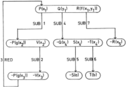
S = {{P(x), Q(y), R(f(x, y))}. {-P(g(x)), V(x)}, {-P(g(x)), -V(x)}. {-Q(x ), S(x), -T(x) } , {-s(a)}, {-S(b)}, {T(b)}. {-R(x)}}is a set of eigtt input clauses. Figure 1 shows a closed deduction plan for s. The edges are drawn in such a way that they begin beyond the starting literal and point to the target literal. There fore they are only labellad by their type and, beyend it, by the numbers of the steps in the plan construction within which the edges were drawn. The literal s -P(g(x 2 J), -V(x 3 ), -Q(x 4 ), -S(a), T(b), and -R(x 5 ) arc key literals, the other literals are subproblems. The first clause
in S is the basic node, it is a predecessor of all nodes.
Definition
Let G be a deduction plan and e an edge of G with label (t,u,v), where (omitting the sign) u = P(u , ... ,u ), v = P(v 1 , ... ,v) 1 n n (n ~O) To e a constraint set C(e) is as signed by
A constraint set C(G) is assigned to G by
G is called correct iff C(G) is unifiable. 8(G) denotes the most general unifier of C(G) . 8(G)os(G) is the clause derived from G. If G is c losed, the clause derived from G is the empty clause.
Soundness and completeness of the de duction plan method are shown in the re ferences given above.
4 . Unification Graphs With Constraints
Unification by means of unification graphs with constraints is closely related to the unification method of Cox, (Cox 1981). It simplifies this method but is still sound and complete. Cf. for this section (Di lger and Janson 1983) and (Dilger and Janson 1984).
The unification process starts with a constraint set c. By two steps, the trans forma t lon step and the sorting step, it yields a unification graph with constraints, uwe for short , fo r C. A UwC consists of
- the node set V(UwC) = SEXPR(C)
- the label set I (UwC) = 2c - the edge set E(UwC) = EU(UwC) U ED(UwC) where EU(UwC) c V(UwC)X(2C-{~})xV(UwC) and ED(UwC) ~ V(UwC)x {~} XV(UwC)EU (UwC) is a set of undirected e dges, ED(UwC) a set of directed edges. Construc tion of UwC starts with the initial graph Uwc 1 which consists only of the nodes.
EU(UwC) is determ~ned in the transforma tion step, ED(UwC) in the sorting step.
Definition
A path in UwC which contains only edges from EU(UwC) is called a connection. A connection v = p 1 ,e 1 , ... ,en,pn+l is called s im p 1 e i f f p . t p . f o r a 11 i, j ( 1:0 i < j :O n + 1 ) . ~ J
A closed path in UwC which contains at least one edge from ED(UwC) is called a loop. A loop is called simple iff Pi ~ Pj
for all i,j such that l <i<j<n+l. If e = (p,a,q) is an edge in E(UwC), then a is called the value of e, denoted val(e) a. Let w = p 1 ,e 1 , ·.· ,en,pn+l be a path in
UwC. Then the value of w is
The transformation step
The algorithm of the transformation step can be found in (Dilger and Janson 1984). It draws undirecteo edges between the nodes ~ the followin~ way: If c. = {p,q} is a constraint, the nodes p and q ar,e connec ted by the edge e = (p,{ci},q) .This re sults in a (possibly empty) set of new constraints , which are treated later on in the same way.
Example
The initial UwC consists only of the nodes SEXPR(C) and is shown in figure 2. The first constraint c is removed, an appro priate undirected ~dge is added to the UwC and the new constraints {s,u} and {z ,F(y,y)} are added to the constraint set.
Now the second constraint is removed from the constraint set. Because u is a variable, there cannot be formed any new constraints, only an edge is added to the UwC. The remaining two constraints are treated as the second one. Because they had their origin in the first constraint,
Gls,zl G(u,F(y,yll
z
F!y,yl
Figure 2: The initial UwC for the constraint sei C
the edges in the UwC are labelled by {c 1 } . At the end of the tr ansformation step tfie UwC has the form represented in figure 3 .
The sorti n g step
The transformation step c l assifies the nodes of UwC in such a way that two nodes belong to the same class iff there is a connection between them . I n the example above we have four classes. In the sorting step, first a graph U is constructed which consists of these classes as nodes and which has a directed edge labelled by f from class X to c l ass Y iff there is a term f(p 1 , ... ,pn) i n X and an expression Pi (i E {1 , .·. , n}) in Y.
G(s, zl G(u,F(y, y))
z
F(y, yl

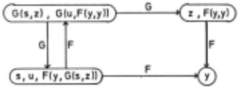
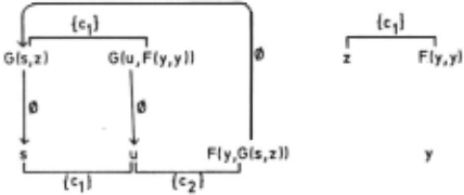
This graph is shown for the example in figure 4. Now the edges of U which belong to a cycle are added to the UwC as edges between the appropriate nodes and labelled by ~ . So we get the complete UwC of figure 5 .
Soundness and completeness of the uni fication algorithm are proved in (Dilger and Janson 1984) . The main theorem is: A constraint set C is unifiable iff all terms in UwC which are connected by a simple con nection begin with the same function sym bol and UwC contains no simple loops .
Thus, e.g., our example constraint set is not unifiable because the UwC of figure 5 contains a simple loop.
5. Intelligent Backtracking
If during the unification process a unification conflict has been detected, i.e . a clash (unification of terms with different function symbols) or a cycle, the actual deduction plan is not correct . One or several steps in the construction have to be reset in order to get a correct plan. By means of the information kept by the UwC these steps can be determined im mediately . The numbers of the deduction steps are contained in the labels of the undirected edges of UwC. Therefore, we have to examine the values of certain paths through UwC. First, the relevant values are gathered in the sets ATTACH and LOOP.
ATTACH := {a c Cla is the value of a simple connection in UwC between te rms p and q w i th differ ent function symbols}
We define:
The minimal disjunctive normal form of BUNIF has the form
for some k ~ l, where each B. is a conjunc tive term. From B~NIF the &inimal conflict
sets are determined by
For details cf. (Dilger and Janson 1984).
Example
Consider the deduction plan of section 3, represented in figure 1. Following the edges according to their numbers we get the constraints
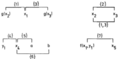
The UwC for these constraints is shown i n figure 6. It has no dire c ted edges . because the graph U, constructed in the sor tin g step , conta ins no cyc les .
There i s a c lash in the UwC, namely a simple connection between a and b . There fore , ATTACH = {{5 , 6}} . Clearly , LOOP = ~ - Thus, BATTACH = 5 V 6 · 8 LOOP = 1 ' 8 UNIF = 5 v 6 = B~NIF a nd mcs 1 = {5} , mcs 2 = {6} .
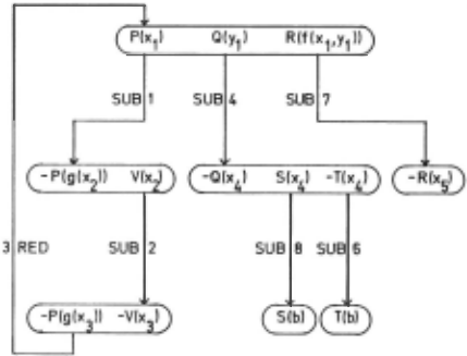
Backtracking is performed as foll ows . Take fo r the back track ing step mcs 1 = {5} . Edge nurober 5 and node -S(a) are removed from the plan. Thereby , the literal S(x 4 ) becomes an open subproblem. But there is ano ther clau se in t h e i np u t c l ause set which fits ~o close the li ter~ l, namely { - S(b)} . This yields the closed correct dedu ction p l an of f i g u re 7 . The reade r is invited t o check that b acktrack i ng with ncs 2 = {6 } does not res u lt in a closed p l an .
6. Th e S t ruc t ure Of ASSIP-T.
In ehe deduc t ion plan method ; deduc tion and unification are separated from each other. For d edu ction, t h e data st r uc ture "deduction p l an " is used , for unifi cation the data structu re "unification
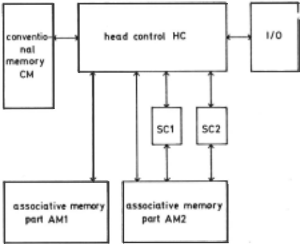
graph with constraints ". In ASS I P- T, both are kept in appropriate parts of the as sociati v e memory . Thus , t h e associative memory is divided in two main parts , AMl for the deduction plan and AM2 for the UwC , cf . figure 8. The control unit of the processor consists of four components:
- the head control HC
- two subcontrols SCl and SC2
- a conventional memory CM
The subco ntrols ope r ate on the UwC . They can work independently from each other , b u t under control of HC , s o they can work in para l lel and this is u seful during t h e initial cons t ruct i o n of the UwC and during its reconstru ction after a backtracking step. Thus , we h ave not only parallel access to the data in the associative memories , rather t h ere are two further steps to parallel processing: one by the parallel treatment of deduc tion plan and UwC, the other by the use of SC1 and SC2 in parallel. For details cf . (Dilger and Schneider 1985). For an introduction to and a survey on the field of associative processors cf. (Fu and I c hikawa 1982) , (Kohonen 1984) , (Parhami 1973) and (You and Fung 1975)
7 . Associative Memory Oriented Data Structures
Several da t a structures are us ed for an associative memory oriented repres e n tat i o n of deduction plans and UwCs, i.e. representations that can easily b e mapped on associative memories. The design prin ciples for the data structures are:
- Deduc t ion plan and UwC- both being graphs - are taken as sets of nodes tagether with their e dges.
- 2 . A clause tagether with all its variants in represented as only one data obj ec t a nd therein their constant part is re presented only once . The same hold s f o r the terms of the UwC .
Due to lack of space we omit the data s tructures , which can be found in (Dilger an d Schneider 1985), and only give some idea of them .
For each literal , we keep in its variants-part the edges to other literals, represented by the target literals and the edge labels , becau se in fact they are drawn between variants of c lauses. This way of storing edges can be thought to be similar to the way they are drawn e . g . in figure 1 .
The nodes of the UwC are variants of expre ssions. Therefore , we store all ex pressions which are variants of one a n othe r in the same part of AM2 (cf . sec tion 8) tagether with the edges incide nt of them.
Because we build variants by just indexing the variab l es ( cf . figure 1) , we are able to represent the informati o n "edge e is incident to node t" by simply storing the index of t ' s variables at e , too. Storing directed edges is done in a mo st efficient way, which j u st ne e ds one bit for each argument of the respective term .
- 8 . Representation And Handling Of The Data S t ructures In The ASSIP - T Memory
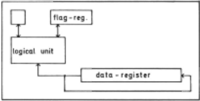
We will sketch here the representation of the UwC in the memory part AM2 . It is similar for the deduction plan . AM2 is divided into severa l parts , one f o r each object of type EXPRESS I ON (th at is , an express i on , its variants and the edges incident to them) . Every AM2 - part con sists of a linear array o f ce l ls and is provided with a special control, called th e "EXP - contro l". The entries in an ob ject o f type EXPRESSION can all be repre sented by the data t ypes INTEGER and 2 BOOLEAN . Therefore all cells of the AM parts have th e same form. They consist of
- a logical unit
- a contr o l bit
- a 4 bit flag register
- a 32 bit data regi ster
cf . figure 9 . The purpese of the f lag re gister is t o characterize the type of in formation whi c h actually is stored in the data regi ster , e . g. i nde x and class of va riant s , information a bout edge s etc . Thus , each cell can store an arbitr ary par t of a n EXPRESSION.
The EXP - control has to perform e ntry, c hange and q uery instructions on the com ponents of a n obje c t of type EXPRESS ION. The head control on the other hand just has to broadcast i nformation to the AM2parts and t o gather it from them by means of instruction s like
"FOR ALL <expression> WITH <condition>
DO <instruction> "
or "FOR ONE <expression> WITH <condition>
DO <instruction>"
Thus , the two- level organisation of the ASSIP - T memory corresponds to a two-level eva luation of the instructions.
9. Conclusion
As far as we know there is no other approach similar to ours . The archi tec ture of the fi fth generation infere nce machine is data flow oriente d and does not take into consideration associative access to data cf . (Moto-oka and Fuchi 19 83) . The mai n probl ern with o ur approach is the s t o rage of the unific ation graph be cause its nurober of edges has an upper b o und that is exponential with respect to the nurober of deduction steps . One may assume th a t this upper b ound will never be reached in practice, but we have to werk out an other representation of the edges. By means of several head control-subcontrol groups, we should be able to perform aR parallel as well as AND-parallel pro cessing due to the Separation of qeduc tion and unification.
@inproceedings{ijcai1985p242,
  title     = {ASSIP-T: A Theorem-Proving Machine},
  author    = {Dilger, Werner and Schneider, Hans-Albert},
  booktitle = {Proceedings of the Ninth International Joint Conference on
               Artificial Intelligence, {IJCAI-85}},
  publisher = {International Joint Conferences on Artificial Intelligence},
  editor    = {Aravind Joshi},
  pages     = {1194--1199},
  year      = {1985},
  note      = {Theorem Proving},
  url       = {https://ijcai.org/proceedings/1985/242},
}
TY - CPAPER TI - ASSIP-T: A Theorem-Proving Machine AU - Dilger, Werner AU - Schneider, Hans-Albert T2 - Proceedings of the Ninth International Joint Conference on Artificial Intelligence, IJCAI-85 PB - International Joint Conferences on Artificial Intelligence PY - 1985 SP - 1194 EP - 1199 UR - https://ijcai.org/proceedings/1985/242 ER -Copied
Machine-readable versions of this paper, for tools and AI agents:





