
SIGMA: A Framework for Image Understanding - Integration of Bottom-Up and Top-Down Analysis
Proceedings of the Ninth International Joint Conference on Artificial Intelligence. Perception. Pages 908-914.
© 1985 International Joint Conferences on Artificial Intelligence
Abstract
The framework and control structure of an Image understanding system SIGMA are presented. SIGMA consists of three experts: Geometrie Reasoning Expert (GRE) for spatial reasoning, Model Selection Expert (MSE) for appearance model selection, and Low Level Vision Expert (LLVE) for knowledge-based picture processing. This paper mainly describes the control mechanism f01· the spatial reasoning by GRE, where bottom-up and top-down analyses are integrated into a unified reasoning process.
- REFERENCES Binford, T.O . , "Survey of model-based image analysis systems," The International Journal of Roboti cs Research, Vol. 1. No. 1, pp.18-64, 1962.
- Nagao, M. and Matsuyama, T., "A structural analysis of complex aerial photographs," Plenum, 1980.
- Tsotsos, J.K., "Temporal event rec ognition: a n application to left venti c ular performanc e," Proc. of 7t4 IJCAI, pp.900-907, 1983.
- J{avens, lf. and Ma c kwot•th, A. , "Representing knowledge of the visual world," IEEE Computer, Vo l. 16, No. 10, PR,• 90-96, 1983.
- Russell, D.M., Where do I Iook now? : modeling and inferring object loc ation by c onstraints," Proc . of Pattern Recognition a.nd Image Processing, pp.175-183. 1979.
- Selfridge, P.G., "Reasoning about succ P.ss a.nd failure in aerial image understanding," Ph .D. Thesis, TR 103, Univ. of Rochester, 1982.
- Brooks, R.A., "Symbolic reasoning a mong 3D mod e ls and 2D images," Artific ial Intellige n ce, Vol. 17, pp.285-348, 1981.
- Nozif, A.M. and Levine, M.D., "Low Ievel image segmentation: an expert system," IEEE Trans. Vol. PAMI-6. No. 6, p,p.555-577, 1984-.
- Minsky, M.L., 'A framework for r e presenting knowledge," in The Psy c hology of Computer Visi o n (P.H. Winston ed .), Mc Graw-Hill, 1975.
- Matsuyania, T. et al, "An expert system for top-down image tation, " (in Japanese) Technica.l Report of W Group on Computer Vision of IPS Japan, 1985. Fi g . 16 Final obje c t 1nstances
References were extracted automatically from the PDF and may contain errors.
Full text extracted automatically from the PDF; figures, tables and equations may differ. The PDF is the version of record.
1. INTRODUCTION
Many experimental image understanding systems have been developed to test the feasibility of Image understanding[l-7]. The followings are some problems in building an image understanding system which have not yet been treated successfully.
( 1 )Segmentation
There a.re ma.ny methods of segmenting an image to exh·a.ct objects. Each method has its advantage and disadvanta.ge. How to select and/or combine appropriate melhods is a basic problem in image understanding.
(2)Diversity in Appearance
2D appearances of a depending on viewing angles. 3D object vary greatly On the other band, an object ha.s many diverse appearances. For example, houses in a subn1·ban area have many possible shapes, sizes, and colo··s. How to limit the number of possible appearances and intelligently select the ones to try (settl'ch) is another problem.
(3)Representation and utilization of Pomain Knowledge
An image understanding system needs lo have domain knolfledge to construct an interpretation of the image. Usually, the sources of knowledge are diverse and redun<J.unt. Reqnü·ements that must be satisfied by an object a1·e specified in many different ways, and each of lhem gives only a weak constraint. Knowing that only some of tne constraints for · an object are satisfied is not enongh to assign the object Iabel to an image feature(e.g. region). On tbe otber band, failure to satisfy some of the constraints does not indicate that the image feature cannot be an object. How to organize and use domain knowledge is another problem.
In this p<lper, we desc1·ibe the framework and control strncture of an image understanding system SIGMA. The followings are the basic ideas incorporated into SIGMA to solve the above three problems.
( 1 )Knowledge-Based Segmentation
It is advantageaus to use a knowledge-based Vincent HWANG Center for Automation Research University of Maryland College Park, Maryland 20742 U.S.A.
segmentation system to process an image(6][6][10). Many st.udies have been done on picture processing operators. Their characteristics have been weil studied, such as effectiveness in extra.cting given types of image features(e.g. region, line) in a given environment, required cost of computation, and possible artifacts caused by the operators. A knowledge-based segruentation system uses such knowledge abont the opet·a.tors to realize efficient and reliable extraction of required image feat>~res.
(2)Evidence Accumulation for Spatial Reasoning
An image understanding system builds interpretations by esl.ablishing relalions among objects, and searching for missing objecls by analyzing the image. Objects found (object instances) can be used to predict missing objects by generating hypotheses. Hypotheses from various sources can be combined to guide the searching process[5, 6]. Such accumulation of evidence from different sources decreases the total amount of effort spent in the search and increases the reliability of the analysis.
(3)Appearance Model Selection Based on Contextual Information
As desc1·ibed above, an object can have many diverse appearances. When an image understanding system seat·ches for a ruissing object, it should use contextual information to predict the most likely appearance(s) of the object. Given an appropriate description of the cont.ext where the target object is embedded, its possible appearance(s) in the image. can be predicted.
2. OVERVIEW OF THE SYSTEM
Fig. shows the organization of the entire system. Tt consists of the following three experts.
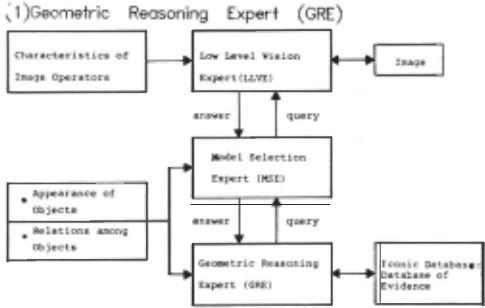
This expert is the central reasoning module in the system, and utilizes a symbolic hierarchical model for the possible spatial organization of objects in the world. The geometric reasoning performed by this expert (evidence aecumulation) integrales both bottom-up and top-do.,..n analysis processes into a unified reasoning process. All of the partial evidence obtained during the interpretation are stored in a common database (lconic Database in Fig. 1), where consistent pieces of evidence are accumulated. GRE first establishes local en vi r·onments (contexts) using the accumulated evidence. Then, either the bottom-up analysis to establish a relation between objects or the top-down analysis to find a new object are activated depending on the nature of a focused local environment. In the top-down analysis, GRE first reasons about its goal (the target object t.o be detected) and where to analyze the image. Then it asks Model Selection Expert to perform the analysis.
(2)Model Selection Expert (MSE)
This expert reasons about the most promising appearance models to use in searching for the object in the image. This model selection is p e rformed based on the contextual information provided by GRE. Knowledge about objects is represented at several Ievels of specificity. For example, an object class "house" is a generalization of many specifically shaped types of ho\lses. GRE delermines the general class of objects to sear·ch for (e.g. "house") while MSE determines which specia lization (e.g. reetangular house) should be looked for. In addition to this reasoning, MSE performs geometric transformation from t.he scene domain to the image domain.
(3)Low Level Vision Expert (LLVE)
The appear·ance model determined by MSE is given to this expert. LLVE performs picture processing to extr:act the image feature cor..-esponding to the specified appearance mode l. It selects appropriate picture pr·ocPssing operators and determines efficient and effective process sequences based on the knowledge about picture processing methods(as for details of LLVE, see[lO]).
3. EVIDENCE ACCUMULATION FOR SP A TIAL REASONING
It is widely accepted that image understanding systems should incorpor·ate both botlom-up and top-down analyses. The use of geometric relations, however, is very different in the two analysis processes: consistency vei"ification in bottom-up analysis aud hypothesis generation in top-down analysis. An important cha.r·acteristic of our evidence accumulation method is that it enables the system to integrale both bottom-up and top-do.wn processes into a single flexible spatial r easoning process.
3.1 Principle of Evidence Accumulation
The spatial reasoning using the evidence accumulation method is p erfomed by the Geometrie Reasoning Expert. Its principle is as follows.
Let REL(Ot,02) denote a binary geometric relation between two classes of objects, 01 and 02. This relation can be represented using two functional expressions: 01 = f(02) and 02 = g(OI).
Given an instance of 02, say s, function f maps it into a description of an instance of 01, f(s), which saUsfies the geomeh·ic r·elation, REL, with s. The analogous inlerprelation holds for the other funclion g.
In SIGMA, knowledge about a class of object is repr·esented by a frame [9), and a slot in t.hat frame is used to represent a function such as f or g . A slot contains a group of production rules, ea ch of which consists of a precondition and an action. A precondition represents a set of conditions specifying when the function can be activated. An action represents a compulational procedur·e corresponding to lhe function, which produces the description of the related object.
Whenever an instance of an object is created and the conditions are satisfied, the function is applied to the instance to c reate a "hypothesis" (expectation) for another objecl which would, if found, satisfy the geometric relation with the original instance (Fig. 2(a)). A hypothesis is associated with (Fig. 2(b)} (i) a prediction area (locational constraint) where the target object instance may be located, and {ii) a set of constraints on the target object instance.
All pieces of evidence (hypotheses and object instances) are s tored the iconic database(Fig. 1), wher·e accumtilation of evidence (i.e. recognition of consistent hypotheses and instances) is performed. This database con tains a.n i conic data structure {i.e. hro dimensional atTay for 2D scene analysis) to represent locational constraints associated 1rith the slored pieces of evidence. They are represented as regions on this a rray. GRE uses ovedaps among the regions to index mutually consistent pieces of evidence. Note that this array r·epresents the world under analysis and its coordinate system is defined independently of that of the image. Besides this loca tional infot·mation, symbolic information such as r·elations among and properlies of object insta nces is also stored in this database.
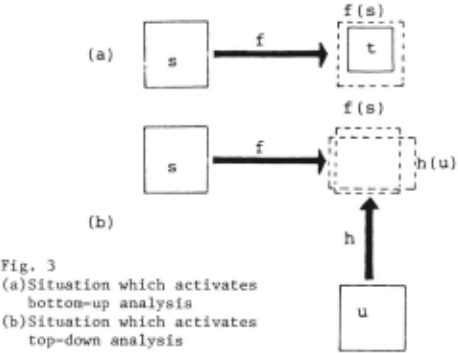
Suppose object instance s creates hypothesis f(s) (based on relation REL) for object 01, which overlaps with an instance of 01, t (Fig. 3(a)). lf the set of constraints associated with f(s) is satisfied by t, these bro pieces of evidence are combined lo form what we call a "situation". That is, a situation is defined by a set of mutually consistent pieces of evidence. GRE unifies f(s) and t, and establishes the rela.tion REL from s to t as lhe result of resolving the situation. This is the bottom-up process to establish a geometric relation hetween a pair of object instances.
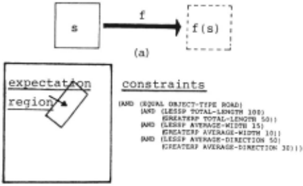
Fig. 2 (a)Hypothesis generation (b)Description of a hypothesis
On the other hand, a situation may constst or overlapping hvpotheses alone(Fig. 3(b)). Then their unification lea<\s GRE to search for an instance of the required object in the image. The expert asks MSE to detect the instance, which in turn activates LLVE. If the instance is detected, it is inserted into the iconic database, and the relations between the new instance an,i the "source" instances, which generated the hypotheses, are established. This process is the top-down analysis to Ond a missing object. Fig. 4 shows goal specifications to MSE and LLVE in the top-down analysis.
3.2 Handling Part-Whoie Relations
Two ~ypes of geometric relations are used in our system: "spatial relation" (SP} and "part-whole relation" {PW). These two types of relations are used differently in the system. PW relations specify hierarchies which represent objects with complex internal structures, while SP relations represent geometric relations between diffm·ent classes of objects. While hypothesis generation by an SP relation is done as explained above, the use of PW relations is different.
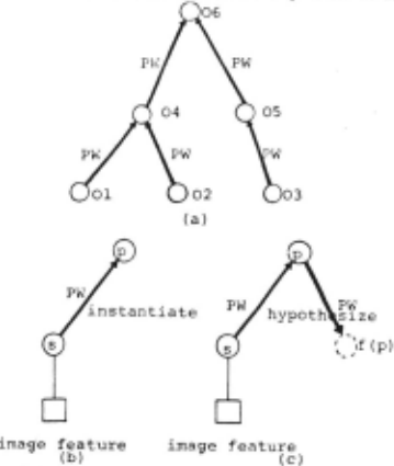
Suppose the PW hierarchy illustrated in Fig. &(a) is given. The system uses Pli' relations both to group parts into a whole and to predict missing parts. In general, the objects corresponding to leaf nodes in the hierarchy are instantiated first, because their appearances are simple and correspond directly to primitive image features. The presence of a higher Ievel object instance is represented symbolically by an instantiated hierarchy. This implies that no iconic description (i.e. region) representing higher Ievel object instances is stored in tbe iconic database. (Note that hypotheses for higber Ievel objects have iconic representations and as a result, can interact with other pieces of evidence.)
Let s denote an instance of object class 01 (Fig. 5(a)). Then, it can directly instantiate its parent object through the PW relation instead of generating a bypothesis as in case of SP relations(Fig. 5{b}).
This bottom-up instantiation through a PW hierarchy is controlled by a "kernel list" associated with each objP-ct class. An object instance in our system is in one of two instantiation states: fully-instantiated and partially-instantiated. The kernel list is used to discriminate these two states. The Iist consists of a set of sublists. Suppose object 0 is composed of part
D
objects Pt. P2, .. . ,Pn. Each sublist in the kernel Iist of 0 specifies a subset of jPt, P2, ... ,Pnl. Object 0 is fully instantiated if all parts objects in at least one sublist are fully instantiated. Otherwise it is partially instantiated. Only a fully instantiated object can instantiate its parent object via a PW relation.
When a parent object is instantiated, it may then generate hypotheses for its missing part objects (Fig. 5(c)). That is, no instantiated part object generates hy}lotheses for tbe othea· part objects at the same Ievel of the PW hierarr.hy.
PW relations are represented in the same way as SP relations. That is, a PW relation is represented by f (GOAL (AND {EQUAL OBJECT-TYPE HOUSE)
(ANO (LESSP AREA 47-5-)
(GRE.ATER.F AREA 250)) )
(LOCATION (AJ\0 (LESSP X 1000)
(GREATERP X lOO)
(LESSP Y 2000)
(GREATERP Y 300)))
(CONTEXT (HOUSE-GROUP002, HOUSE-GROUP006, ROA.D005 ) ))
(a) Goal specification to MSE
(unit is('>quare)feet A."1d. (X,Y) i& in the world coo rdi natel
((GOAL (AND (EQUAL OBJECT-TYPE RECTANGLE-HOUSE)
(AND (LESSP AREA 400)
(GREATERF AREA 200))
(LOCJ..TION (AND (LESSP X 1000)
(GREATERP X 100 )
(LESSP Y 2000)
(GREATERP Y 300))))
- (b) Goal sper.ification after selecting a specific object model
((GOAL (EQUAL IMAGE-FEATURE-TYPE RECTANGLE )
(AN~ (Lf.SSP AREA. 230 .1
(GREATERP AR.E.A 115 ) ))
(LOCATION CAND (EOAL START-I 24)
(EOUIU. STA.R'!"-J 30)
(EQUAL END-I 110)
(EQUAL END-J 130))))
(c) Goal specification to LLVE
- (unit is number of pixels end (I ,J)iiS in the picture coordinate)
Fig.4 Goal specification in a top-down analysis a slot in a frame, where a set of production rules are stored. Conditions for both the bottom-up instantiation and top-down hypothesis generation througb a PW bie··archy are ··epresented by preconditions of the production rules. Computational procedures to generate parent instances and hypotbeses for part objects are rep1·esented as actions of the rules. (The interpretation process to construct instantiated PW bierarchies (i.e. recognition of complex objects) will be described in Section 4.5. )
4. AERIAL IMAGE UNDERSTANDING BY A PROTOTYPE SYSTEM
This section describes the knowledge organization and analysis process of a p1·ototype system fo·· aerial image understanding. The system is implemented on VAX 760 and is written in FLAVOR, LISP, and C. The model selec tion and low Ievel vision experts in this system are realized by simple functions written in LISP and C.
4.1 Knowledge Representation
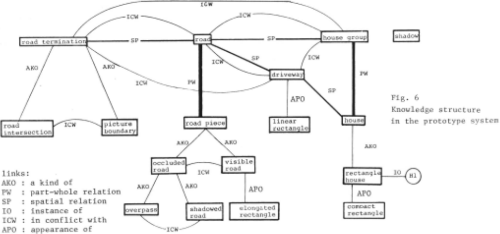
fig. 6 illustrates the knowledge organization used in the prolotype system. As described above, an object class is represented by a frame, which consists of slots. Information stored in the slots includes attributes of the object and its relations to other objects. Besides these slots, a set of constraints among object attributes are sto··ed in a frame to represent their allowable value ranges(7). These constraints are basic requirements to be satisfied in object recognition.
linked with an in-conflict-with (ICW} relation. {6)APO :rep1·esent appearance of object
4.2 Initial Segmentalion
The first analysis of an image is initiated by MSE. At the very beginning of the analysis, there is no object instance in the systeru. MSE examines the kuowledge stored in the system and selects objects with simple appearances. Then, it asks LLVE to extract image features which match the selected appearances. The basic constraints on object attributes are associated with the goal specification to LLVE. All image features found by LLVE are returned to MSE, which then inslantiates co1-responding object instances and inserts them iuto the iconic database. These instances are seeds for reasoning by GRE.
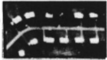
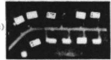
Fig. 7(a} shows an aerial photograph {black and white) used in the experiment (250 X 140 and six bits for each pixel). Figs. 7{b){c) Blustrate the instances of house and road-piece extracted by the inilial segmentation. Note that the segmentation in our system is dynamically performed on request and that no fixed set of iruage features (e.g. regions} to be interpreted are formed by the initial segmentation.
4.3 Interpretation Cycle of GRE
GRE iterates the following steps until no change is done in the iconic database.
(a) ~- .. ....
The relations used to associate frames are:
(0PW :represent geometric structures of objects with complex internal structures
{2)SP
{3)AKO
{4110
:geometric relations between objects
:specialization/ generalization objects relations among
:represent instances of a class of object
(5)lCW :Some pairs of objects cannot. occupy the s~me (c) location in an image. For tnstance, a regton cannot be interpreted as both house and road at the same time. Pairs of frames representing objcct classes which cannot occupy the same location are
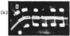
- Fig. 7 Initial segmentation
- (a) An aerial photograph
- (b) Road piece instances
- (c) House instances
- (1} Each instance of an object generates hypotheses about related objects using functions stored in the object model. Object instances in PW hierarchies instantiate their parent objects, which then generate hypotheses for missing pa.-ts.
- (2} All pieces of evidence (both hypotheses and instances) are stored in the iconic database.
- Consistent pieces of evidence are combined to establish "situations".
- (4} Focus of attention : since the.-e are many situations, the most reliable situation is selected. Each piece of evidence has a reliability vaiue, and the reliability of a situation is computed from those of its constituent pieces of evidence.
- (5} The selected situation is resolved, which results eitbet· in verification of predictions on the basis of previously detected/ constructed object instances m· in top-down image processing to detect missing objecls.
The system has one additiopal post-processing: During the analysis by GRE, conflicting pieces of evidence may be generated. Comparing Fjgs. 7 (b) and (c), for example, two road-piece instances overlap with house instances. These interpretations are considered as conflicting. GRE maintains all possible interpretations lhroughout the analysis. The final inte.-pretation process then selects the maximal consistent interpretation. At this stage, all partially instantiated objects and their parts are removed, because enougb evidence to support their existence has not been obtained from the analysis.
In the above case, if both E1 and E2 are instances, GRE records them as conflicting interpretations and performs independent analyses based on them. {See Section 4.4.4.)
4.4.3 Constraint Consistency
After eliminating all conflicting intersections from the lattice, the remaining intersections a.-e checked to determine if their associated sets of constraints are consistent. Let Et and E2 denote the non-conflicting evidence under· consideration. One of the following conditions must hold:
- {a) The object categories of Et and E2 are the same, {b) t.here is a path between the lwo categories consisting of PW relations,
or
- {c) one of the two categories is a subcategory of the other, according to the AKO hierarchy.
As shown in Fig. 9, suppose a grandparent object in a PW hierarchy has been instantialed by an instance of a leaf node object s. Let p and q denote instances of the parent and grandp<).rent objects. q as weil as p generates hypotheses for its missing parts, say g(q). Suppose that g(q} itself has parts and one of them has already been instantiated Let t denote that instance.
4.4 Consistency Examination among Evidence The consistency among pieces of evidence is examined based on:
- prediction areas of hypotheses and locations of instances
- object categoriP.s of evidence
- constraints imposed on properties of hypotheses and instances
- (4} ··elations among sources of evidence.
4.4.1 Intersection of Prediction Areas
Fig. 8(a} shows all inte··sections formed from four pieces of evidence Et, E2, E3, and E4 in the iconic database. A partial ordering on intersections can be constructed on the basis of region containment. Intersection OPt is less than OP2 if region OPt is contained in ··egion OP2. Fig. 8(b) shows the lattice rep1·esenling the partial ordering among the interscctions in Fig. 8(a). Each intersection consists of some set of hypotheses and instances. Situations are only formed among intersecting pieces of evidence (i.e. satlsfying locational constraints). In other words, this lattice is an index to search for consistent pieces of evidence. To examine the consistency among pieces of evidence, it is sufficient to examine all intersections containing only a pair of pieces of evidence and then to propagate the ··esults through the lattice.
4.4.2 Conflicting Evidence
Let OP be the intersection arising from evidence JEt. E2j and Iet OBJt and OBJ2 denote the object categories of El and E2, respectively. If OBJt and OBJ2 are linked by an ICW relation, then El and E2 a1·e said to be conflicting, and OP is removed from the Iatlice. The r emoval of OP is propagated through the lattice, and any intersections contained in OP are also removed.
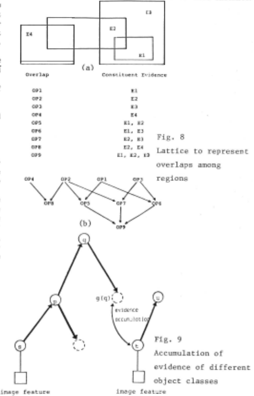
Then, if instances s and t are really parts of the same obj"c t, 1·egions of g(q) all4 t will overlap with each other and will be consistent. (Note that instance u cannot inte1·sect wilh g{q) directly since no iconic description is associated with u in the database.) In this case, although the object classes of g(q) and t are different, they can be consistent since their object categories are linked by a sequence of PW relations.
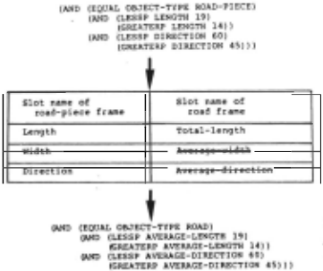
In such a case, since the names of the attributes used in the constraints associated with El {g(q) in Fig. 9) and E2 (t in Fig. 9) are different, they cannot, in general. be directly compared. In this case, the constraints associated with the lower Ievel object (i.e. t) are translated into lhose for the higher Ievel object {i.e. g(q)) by using PW relations. Currently, this translation is done simply by rewriting the attributes (slot names) of the lower Ievel object into appropriate attributes of the higher Ievel object using a "attribute translation table" for the PW relation (Fig. 10). The similar attribute translation is used between object categories linked by AKO relations.
The properties of and/or constraints associated with both pieces of evidence must be consistent. Both constraints associated with a hypothesis and properties associated with an instance represented by a set of linear inequalities in one variable. A simple constraint manipulation system[7] is used to check the consistency between the sels of inequalities.
4.4.4 Relations between Sources of Evidence
Sources of accumulated evidence involved in a situation 1nust not be conflicting. Let Sl and S2 denote the source evidence of El and E2, respectively. lf a piece of evidence is a hypothesis, its source evidence is the instance which generated the hypothesis. An instance is the source evidence for itself. lt is possible that S1 and S2 are mutually conflicting (belonging to conflicting interpretations), but that El and E2 themselves are consistent. In such a case, we do not combine El and E2 into a situation; analysis based on such conflicting interpretations should be p c-rformed independently.
4.5 Resolving a Situation
As described in Sectio!l 3 . 1, one of two actions is tak-en in o1·der to resolve a situation: confirm relation between instances or activate top-down analysis. After the action is taken, GRE provides a description of its proposed solution to the situation to all instances involved in that situation. Each instance then evaluates the proposed solution according to its specific expecta tions.
4.5.1 Resolution Process
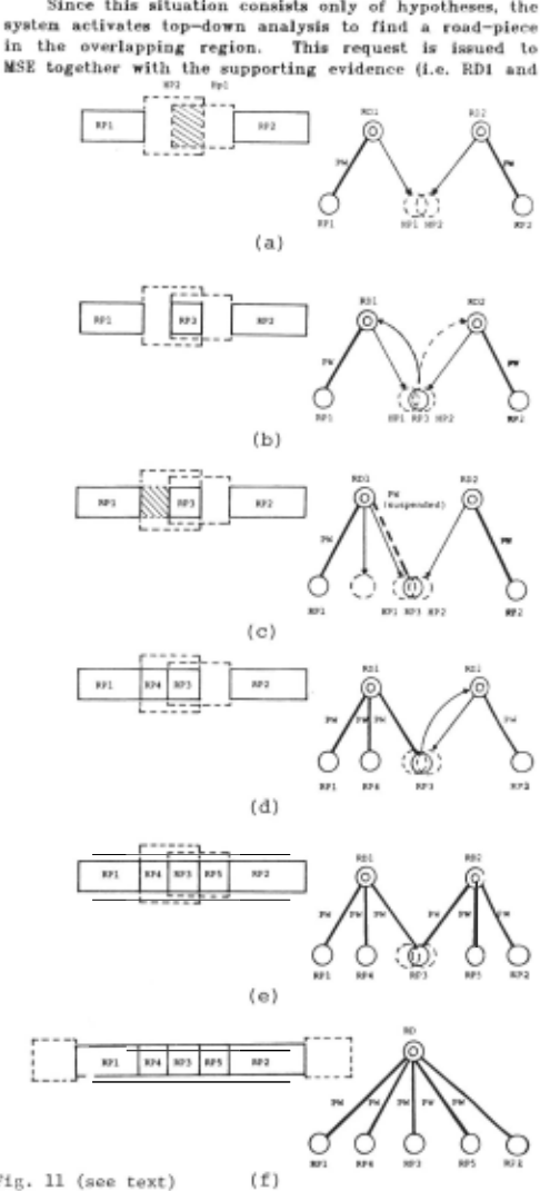
In what follows, the process of resolving a situation is described by using the example shown in Fig. 11. Suppose GRE selected the overlapping region bet-..een two hypotheses genet·ated from two road instances RD1 and RD2 (Fig. 1l(a)). In the symbolic data structure, RDl and RD2 are linked to their part (road-piece) instances RPI and RP2 by PW relations, respectively.
RD2}, so lhal lbe expert can use any available contextual informalion of such supporting evidence.
Assnme that a new road-piece instance, RP3, is created (Fig. 11(b}}. Then, GRE provides this result to the insta n ces involved in the situation, RDl and RD2.
Suppose RDI is the first to be informed of the proposed solution. RDI examines whether or not RP3 saUsfies a II constt·aints required to establish the PW rel a tion with itself. In this case, however, RP3 fails, because RP3 is not adjacent to RPI. (The constraints associated with the hypothesis do not include this type of relalional conslraints.) This failure activates an exception handler, which is also a production rule stored in the corresponding slot in the t·oad frame. Then it issues a top-down request to find a road-piece between RPI and RP3 (see Fig. ll(c)}.
Assurne that another new road-piece instance, RP4, is detected (Fig . 11(d)). Since RP4 is adjacent to RPl, RDI eslablishes a PW relation to RP4, and then to RP3.
Fig. ll(e) shows the interpretation after the same analysis is performeq by RD2. ln this case, howevet·, when RD2 establishes a PW relation to RP3, an exception handlet· in RP3 is triggered, because RP3 has two diffet·ent parents. More specifically, after RD2 establishes a PW r e lation to RP3, RD2 asks RP3 to ckeck its reverse relalion ft·om RP3. An exception handler is activated as a result of this checking process. This handler issues a t·equest to GRE to examine the consistency between two pat·ents. lf they are consistent, GRE met·ges the two PW hierarchies below them into one (Fig. ll(f)).
The hypotheses generated by RDl and RD2 are removed from lhe iconic database. The resultant new road instance in Fig. ll(f) generates new hypotheses for its adjacent. road-pieces at the beginning of the next interpretation cycle.
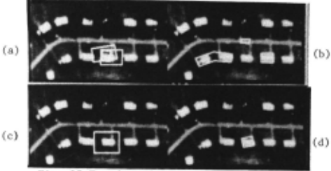
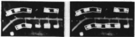
Figs. 12 and 13 Blustrate an example of this process. Fü·st top-down analysis is performed to extract a house Then , a common house instance (i.e. a new detected house instance) are merged into one instance.
4.5.2 Error Analysis
There are several stages in the above example where the top-down request might have failed.
In general, MSE has the ability to deal with such faijut·es. For example, MSE analyzes the request to find RP3 (Fig. 11(a)) by firsl assuming the road-piece to be detected is a visible road(Fig. 6), and issues a request to LLVE. lf this reque;;;t fails, MSE switches to. the other appearance of a road-piece, i.e. an occluded-road (Fig. 6). The selection between overpass and shadowed road is done based on the cause of the failure returned from LLVE.
lf all effortEO by MSE fail, this Then, GRE reports this to RD1 and theü t·el evant exception diffe t·ent new hypotheses exception handlers, no activated. handlers may be immediate is reported to GRE. RD2, which trigger (if any ). Since genet·ated by such further analysis is
Fig. 14 Blustrates an example of this, where a road inst.ance is reported that ils hypothesis for an adjacent road-piece cannot be verified. Then it removes that hypothesis and newly genet·ates a hypothesis for a road terminator (Fig. 6), assuming that it comes to an termination.
lf a top-down request issued by an instance fails, the instance reports this to GRE. Then GRE activates another instance involved in the focused situation. ln the prolotype system, failures of this type are not take n into aceout in any wa.y.
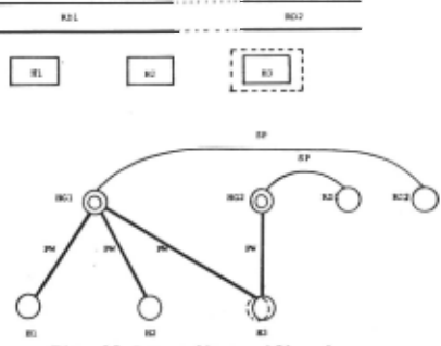
4.5.3 Merging a Pair of Partial PW Hierarchies If a part instance is shared by two parent iustances, the part issues a request to check the similarity between the parents. If they at·e similar, tbe system merges them into one.
Similarity examinalion involves checking whether or not the two parents instances denote (perhaps different pieces of} the same object. For example, RDl and RD2 in Fig. ll(e) should be merged into one, although they do not denote the same (portion of) road.
In pt·actice, according to the request from the system, the more t·eliable of the two parent lnstances to be met·ged ckecks whether or not the part instances of the other instance are consistent with that more reliable parent. The more reliable parent may decide to merge with the othet· parent, that such n merge is not (anq will never be) possible, i.e. both parents are mutually conflicting, or that sufficient information is not available to make a decision.
(c)Road terminator hypothesis Fig. 15 illustrates an example of the third case. Suppose that definition of a house group is a group of regularly ananged houses which face the same side of the same road. As shown in Fig. 15, if two house group instances share a house instance, the similarity examination is performed. lf both house group instances face the same side of the same road instance, then they at·e similar and merged into one. On the other hand, if one (or both) of them has not established such a "facing" t·elation, then it is not possible to verify the similal'ity between them. Moreover, even if the two house group instances have established "facing" relations to different road instances, it is still possible for them to be similar, because those t·oad instances may be merged later.
If the result of the similarity examination is "inr.onclusive", the system records its causes and suspends the action of establishing a new PW relation from a parerd instance to the ahared pat·t instance. In the casc shown in Fig. 15, the relation between HG1 and H3 is suspended. The system records all suspended a c tions tagether with their causes. The suspended action can be reactivated if its cause is resolved by analyzing other situations.
At the final stage of the analysis, the system makes copies of shared part instances involved in the suspended actions, and separates overlapping interpretations. The system does not regard these intet·pt·etations as conflicting, but considers them as possible interpt·etations.
5. CONCLUDING REMARKS
Fig. 16 shows the final results of analyzing the aerial photograph shown in Fig. 7. Although there are several mis-interpretations, they can easily be removed since such interpt·etations at·e j.solated and/or conflicting with the con·ect (maximally consistent) interpretation.
SIGMA is not a completed system and has several pt·oblems to be solved. First, no negative sources of evidence are considered in assessing the reliability of a situation. Introduction of negative evidence requires a more general method of combining evidence. The most difficult problern would be how to coordinate interpretations excecuted in parallel in local areas. In our system, the interpretation of an object with many parls can be initiated from any part in parallel, and partial intcrpretations at·e merged into one gl oba l iuterpretation if they are consistent. This merging process is tt'igget·ed by a local inlet·pret a tion shared by multiple partial interprelation8. The complication explained in Section 4.5.3 in merging partially instantiateq PW hierarchies arises from the intrinsic parallelism involved in our reasoning process. Since lhe cunenl global control is sequencial, the suspension of the reasoning p1·ocess was inlt·oduced t.o cope with the pat·allelism. Mo1·e general and powerful control scheme is necessat·y to manage such parallel rea soning.
ACKNOWLEDGEMENT
The a11thors sincerely apprecia te helphul comments and constrnctive discussions by Profs. A. Rosenfeld and L. S. Davis of Univet·sity of Mat·yland. The firsl author tha nks Prof. M. Nagao of Kyoto Uni ve rsity for giving him this research opportunity. The support of th" U.S. Air Force Office of Science Research unde r Contract F-49620-83-C-0082 is gratefully acknowledged.
@inproceedings{ijcai1985p183,
  title     = {SIGMA: A Framework for Image Understanding - Integration of Bottom-Up and Top-Down Analysis},
  author    = {Matsuyama, Takashi and Hwang, Vincent Shang-Shouq},
  booktitle = {Proceedings of the Ninth International Joint Conference on
               Artificial Intelligence, {IJCAI-85}},
  publisher = {International Joint Conferences on Artificial Intelligence},
  editor    = {Aravind Joshi},
  pages     = {908--914},
  year      = {1985},
  note      = {Perception},
  url       = {https://ijcai.org/proceedings/1985/183},
}
TY - CPAPER TI - SIGMA: A Framework for Image Understanding - Integration of Bottom-Up and Top-Down Analysis AU - Matsuyama, Takashi AU - Hwang, Vincent Shang-Shouq T2 - Proceedings of the Ninth International Joint Conference on Artificial Intelligence, IJCAI-85 PB - International Joint Conferences on Artificial Intelligence PY - 1985 SP - 908 EP - 914 UR - https://ijcai.org/proceedings/1985/183 ER -Copied
Machine-readable versions of this paper, for tools and AI agents:





