
Generalizing Logic Circuit Designs by Analyzing Proofs of Correctness
Proceedings of the Ninth International Joint Conference on Artificial Intelligence. Learning and Acquisition. Pages 643-645.
© 1985 International Joint Conferences on Artificial Intelligence
Abstract
This paper presents a method of learning to solve design problems by generalizing examples. The technique has been developed in the domain of logic circuit design. It involves the use of domain knowledge to analyze examples and produce generalized circuit designs. The method utilizes proofs of design correctness to guide the process of generalization. Our approach is illustrated by showing it can generalize a rotational shift register into a schema describing devices capable of computing arbitrary permutations.
- Carbonell, J. G. Derivational analogy in problem solving and knowledge acquisition. Proceedings of the International Machine Learning Workshop, Champaign- Urbana, Illinois, 1983, pp. 12 -18.
- DeJong, G. F. Acquiring schemata through understanding and generalizing plans. Proceedings of the Eighth International Joint Conference on Artificial Intelligence, Karlsruhe, West Germany, 1983. IJCAI
- Dijkstra, E., W. A Discipline of "Programming. Prentice-Hall, Inc., Englewood Cliffs, New Jersey, 1976. !Kelly
- Kelly, V., Steinbeq;, L., The CRITTER System: Analyzing Digital Circuits by Propagating Behaviors and Specifications. Proceedings of the Second National Conference on Artificial Intelligence, Pittsburgh , PA, 1982.
- Michalski, R. S. "Pattern reco~nition as rule-guided inductive inference." IEEE Transactions on Pattern Analysis and Machine Intelligence 2, 4 (1980), 349 -361 . . !"Minton
- Minton, S. Constraint-Based Generalization . f>roceedings of the Fourth National Conference on Artificial Intelligence, Austin, Texas, 1984.
- Mitchell, T . M. Learning and problem solving. Proceedings of the Eighth International Joint Conference on Artificial Intelligence, Karlsruhe, West Germany, 1983. IJCAI
- !"Mitchell 83bl Mitchell, T . M., et al. An Intelligent Aid for Circuit Red'esign. Proceedings of the Third National Conference on Artificial Intelligence, Washington, DC, 1983.
- Mostow, J. Operationalizing advice : A problem-solvinfi model. Proceedings of the International Machine Learnmg Workshop, Champaign-Urbana, Illinois, 1983, pp. 110 -116.
- I"Mostow 83bl Mostow, J. Program Transformation for VLSI. Proceedings of the Eighth International Joint Conference on Artificial Intelligence, Karlsruhe, West Germany, 1983.
- Salzberg, S. Generating Hypotheses to txplain Prediction Failures. Proceedings of the Third National Conference on Artificial Intelligence, Washington, DC, 1983.
- Silver, B., Learning Equation Solving Methods from Worked Examples. Proceedings of the International Machine Learning Workshop, Champaign-Urbana, Illinois, 1983, pp. 99 -104.
- rutgort 831
- Utgoff, P. E. Adjustinl'i Bias in Concept Learning. ~roceedings of the InternatiOnal Machine Learning Workshop, Champaign-Urbana, Illinois, 1983.
- Winston, P . H. Learning structural aescriptions from examples. In P. H. Winston, Ed., The Psychology of Computer Vision, McGraw-Hill, New York, 1972.
- Winston, P. H., Binford, T. 0 ., Katz, B., Lowry, M. Learning Physical Descriptions from Functional Definitions 1 Examples, and Precedents. Proceedings of the Third National Conference on Artificial Intelligence, Washington, DC, 1983.
References were extracted automatically from the PDF and may contain errors.
Full text extracted automatically from the PDF; figures, tables and equations may differ. The PDF is the version of record.
Introduction
Research in machine learning has identified two contrasting approaches to the problem of learning from examples. The traditional "empirical" approach is based on the idea that an intelligent system can learn from examples without having much prior knowledge of the domain of application. This approach has involved looking at a large number of examples in order to identify similar features. It usually relies on syntactic methods of matching instances and correlating the common features. Examples of this approach include [Winston 72); [Michalski 80). among others. The alternative "analytical" approach takes a different point of view. It assumes that generalization requires a great deal of background knowledge of the domain under study. It typically relies on intensive an·alysis of a single example in order to generalize. The work reported in this paper takes the analytical approach. It has been applied to the problem of learning to design logic circuits. The method involves analyzing single examples of circuit designs and producing generalized designs.
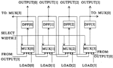
In order to illustrate the technique, consider the circular shift register circuit shown in Figure 1. This device is capable of four operations, rotate right, rotate left, load and no-operation. The operations are controlled by the two bit " select" line {Figure 2). The circuit has been designed using d-type flip-flops, labeled "DFF", and multiplexers, labeled "MUX". A human novice would be capable of generalizing from this example provided he understands the principle of operation behind the circuit. For example, he must know that a d-flip-flop can store one bit of information and that its output is equal to its input delayed by one time unit. The multiplexers are used to route one of four inputs to an output determined by values on their select lines. A novice who understands the operation of this circuit could probably produce similar designs which compute any permutation of This paper will describe a program that attempts to model the behavior of the human novice. The program is able to successfully generalize the shift register into a circuit schema capable of implementing any permutation. The system is given enough background knowledge about the operation of devices like multiplexers and d-flop-flops so that it can understand the operation of the shift register. This knowledge takes the form of rules which can be used to prove that the example design is correct. The original example is generalized into a schema describing all circuits that can be verified using the same proof of correctness.
*This research was supported in- part by the Defense Advanced Research ProJects Agency under contract N00039-84-C-0165.
| SELECT-CODE | OPERATIOI |
| ~~ ~~ | lo Operation Rotate Rifht Rotate Le t Load |
This research is similar in spirit to previous work on analytical methods of generalization. These analytical approaches include "goal-directed learning" [Mitchell 83a). "explanatory schema acquisition" [DeJong 83), "derivational analogy" [Carbonell 83) and "learning from precedents" [Winston 83) . The research reported here is also related to the work on "circuit redesign" reported in [Mitchell 83b) .
The approach taken there involves designing a new circuic by analogy with a previously designed circuit. Our work is different mainly in that it focuses on generalization, rather than analogy. The technique of explanatory schema acquisition reported in (DeJong 83) is similar to ours, although the domain of application is quite different. Our work also differs by focusing on design problems and generalizing both designs and specifications. Other related work includes [Minton 84; Mostow 83a; Mostow 83b; Salzberg 83; Silver 83) .
The Learning Task
Our learning program is envisioned as a component of a complete system for designing circuits according to explicit specifications. The problem solving module for such a system would take circuit specifications as input and produce circuit designs as output. The learning module deals with both specifications and designs. It is intended to take as input a pair (S,D) consisting of specifications and a design which correctly implements the specifications. The goal of the learning process is to produce a generalized design schema (S* ,D*) consisting of generalized specifications and a generalized design. The learning system must generalize the original pair subject to the constraint that the general design correctly implements the general specifications. The entire process has the following four steps.
1. A sample specification and design is input by a teacher.
2. A correctness proof is built to verify the design.
3. The proof is used to guide generalization of the example.
4. The generalized schema is used to solve new problems.
We have chosen to focus on the third step which involves using the proof to facilitate generalization. There are several reasons for concentrating on the generalization step. A great deal remains unknown about precis.ely how causal reasoning may be used to enable generalization. Furthermore, correctness proofs may take a variety of forms and the choice may impact on the extent to which the proofs are a useful aid for generalization. This reasoning suggests investigating the generalization process first and letting the proofs be designed to fit the requirements of generalization. Our generalization program uses proofs built by hand as input. The task of automatically building explanations has not yet been implemented. The task of building proofs is similar to other understanding problems, and has been studied before. The CRITTER system [Kelly 82], is an example.
The Circular Shift Register Example
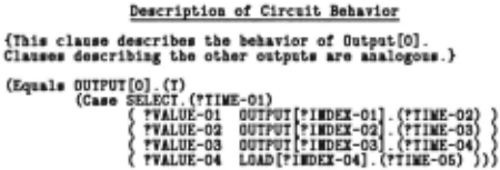
The generalization program works by analyzing three. pieces of information (S,D,P). Two of the inputs are the specifications S and the design D as described above. The third input "P" is a proof tree which verifies that the design correctly implements the specification. The specifications for the circular shift register are shown in Figure 3. These specifications contain a list of inputs and outputs, as well as clauses describing the behavior of each of the four output lines. Each clause specifies the value of an output line at time "T" as a function of the values on the input. lines at an earlier time, "T - 1 ". The "Case" statement is used to specify the circuit's behavior for each of four control states of the SELECT lines. The design of the circular shift register is represented by the data in Figure 4. This representation describes the electrical components and the wire connections between their ports.
Declarations of Input· and Outputs
| lire | Direction | lidth (Bits) |
| SELECT LOAD[0:3] OUTPUT[0:3] | Input Input Output | 2 1 1 |
De·cription of Circuit Behavior
{Thi· clau·e describe· the behavior of Output[O]. Clau·e· de·cribin& the other output· are analocous.}
(Equal· OUTPUT[O].(T)
1 0 OUTPUT 1j.~T- 1
(Ca·e S~EL~gc~~. (Tgg~!g~Jg~:~~: ~~ ~
1 1 LOAD[O . (T- 1) )
{lo operation}
{Rotate Rifht}
{Rotate Le t}
{Load}
Figure 3: Specifications for Circular Shift Register
Declaration· of Circuit Coaponent·
DFF[0:3] {Four D-Flip-Flop·.}
IIUI[0:3] {Four Multiplexers.}
lire Connection· Between Coaponent·
{Only the wire connection· involvinc ·tace zero are ·hown. Connection· involvin& the other ·tage· are analocous .}
{Connect Multiplexer· to D-Flip-Flopa.} (COllECT DFF[OJ.IIPUT IIUI[O].OUTPUT)
{Connect Multiplexer Input[O]'· for to-Operation.} (COllECT IIUI[OJ . IIPUT[O] DFF[O] .OUTPUT)
{Connect Multiplexer Input[1]'· for Rotate Richt.} (COllECT IIUI[O] . IIPUT[1J DFF[3] .0UTPUT)
{Connect Multiplexer Input[2l'· for Rotate Left.} (COllECT IIUI[OJ.IIPUT[2J DFF[1].0UTPUT)
Figure 4: Design Statements for Circular Shift Register
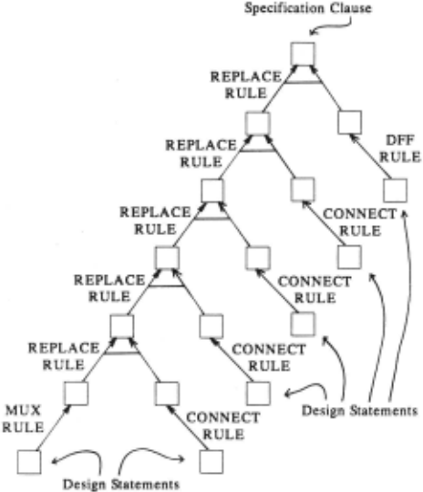
Proofs of correctness are represented as trees. Figure 5 shows a proof tree that verifies a clause describing the behavior of one stage of the shift register. The leaves represent facts about the design and the root contains the specification to be verified. Hence the tree represents a derivation of the specification taking the design statements as assumptions. This proof tree uses four derivation rules. Two of them, the "Dff-Rule", and the "Mux-Rule" describe the behavior of components. The Dff-Rule asserts that a d flip-flop output signal at time "T" is equal to the d-flip-flop input signal at time "T - 1 ". The Mux-Rule describes how a multiplexer can be used to implement a case statement. The "Connect-Rule" asserts that two connected wires have the same signal values at all times. (Ignoring propagation delay.) Finally, the "Replace-Rule" allows equal quantities to be substituted for each other in expressions.
Using the Proof to Generalize
Our generalization procedure is intended to produce a schema (S* ,D*) describing all circuit designs that can be proven correct using the original correctness proof. The proof tree contains information which may be used to identify constraints that must be preserved as the example is generalized. For this purpose, the proof was designed to be processed in both "forward" and "reverse" directions. Running in the forward direction, the tree takes a design at the leaves and produces a specification at the root. In the reverse direction, the proof starts with a specification and produces a design. This suggests that the proof tree could be used to do circuit design by analogy, although that is not the direction taken here. (See [Carbonell 83] .) There are four major steps involved in this method of generalization:
Generalization Procedure
- I . Generalize the specification.
- Propagate the generalized specification through the tree.
- Obtain constraints on the design at the leaves.
- Apply problem independent constraints to the design.
The first step involves systematically removing information from the specification. This is done by changing constants appearing in the specification into variables. The result is shown in Figure 6. The specification now has three types of free parameters. The indices associated with the output wires have been generalized. The boolean control codes and the time values have also been changed into variables. Only on the right hand side of the equality have constants been generalized. The left side was left alone due to a requirement that all output lines have their behavior speci fied by some clause. After all four clauses have been generalized, the specifications can express arbitrary permutations of four bits. In fact, the specifications can express movement of data other than permutations. They can also express arbitrary time delays.
Some plausible generalizations have not been made. For example, it might be desirable to generalize the length of the shift register or the number of different operations the device can perform. These quantities do not appear explicitly in the specifications. They cannot be generalized using the technique of changing constants to variables. Generalizing these quantities would require a more complex representation for the specifications as well as a more sophisticated procedure for generalizing the specifications.
Once the specifications have been generalized, they can be propagated down through the proof tree. This is achieved by having a procedure for each rule which computes the "pre-conditions" for that rule. Given a "post-condition" on the result of a proof rule, the procedure finds "pre conditions" on the antecedents of the rule which guarantee that the post-condition will be true. Each of the proof rules must be written in forward and backward versions. For example, the "Replace Rule" involves eliminating variables when running in the forward direction, and introducing variables when running in the backward direction. This method of backward constraint propagation has been applied in other learning systems such as [Utgoff 83; Minton 84], and the method is formalized in [Dijkstra 76] . After the specifications have propagated through the tree, constraints on the circuit design are obtained at each of the leaves.
The final step involves applying some problem independent constraints to the design statements generated at the leaves of the proof tree. These constraints require that the circuit design meet some general requirements that apply to all designs. For instance, one constraint requires that no input wire be connected to more than one output from another device.
The Generalized Design
A portion of the final design schema is shown in Figure 7. One part of this schema is a list of constraints on the parameters of the generalized specifications. The schema in Figure 7 lists constraints on the time variables "?Time-01 " , "?Time-02", "?Time-03", etc. These constraints assert that the general design can only implement a one unit time delay. When these variables were first introduced, they allowed the specifications to express arbitrary time delays. Now it turns out that the original specifications were over generalized. The time values were constrained as they propagated through the proof tree. This is a consequence of the fact that the proof tree does not represent a reasoning process sufficiently general for implementing arbitrary delays.
The schema in Figure 7 also lists statements describing connections between inputs of a multiplexer and outputs of d-flip-flops. These connections are not specified exactly. They depend on the parameters "?lndex-01 ", "?Jndex-02", "?lndex-03", "?Value-01 ", "?Value-02", and "?Value-03" which appear in the generalized specifications. (The expression "(Number ?Value-01)" represents the integer corresponding to the two bit vector "?Value-01".) These variables fell through the proof tree without having their values constrained. Therefore, the multiplexer inputs may be connected to any of the d-flip-flop outputs. These degrees of freedom allow the schema to implement an arbitrary permutation of the four bits, and an arbitrary choice of control codes. The "Index" parameters determine which permutations can be computed. The "Value" parameters determine the corresponding control codes. This design schema can also be used to implement data rearrangement operations other than permutations.
lire CoDDectioDe BetweeD CoapoDeDte
(COllECT MUI[O].OUTPUT DFF[O].IIPUT)
(COllECT DFF[!IIDEI-01] .0UTPUT KUI[O] . IIPUT[(IOKBER !Y!LUE-01)])
(COllECT DFF[!IIDEI-02].0UTPUT MUI[O] . IIPUT[(IOKBER !YALUE-02)])
(COllECT DFF[!IIDEI-03] .0UTPUT MUI [0] . IIPUT [(lUMBER ?Y.I.LUE-03)])
CoDetraiDte OD �eDerali~ed Variable·
!TIKE-01 = T - 1
!TIKE-02 = T - 1
!TIKE-03 = T - 1
!TIKE-06 = T - 1
!TIKE-04 = T - 1
{CoDDectioDe aDd coDetraiDte are eboWD for etace ~ero ODlJ.}
Figure 7: A Portion of the Generalized Design
Conclusion
It has been shown that domain knowledge can be used to enable an intelligent system to generalize from a single example. In the area of design problems, a proof of correctness is a useful vehicle for applying domain knowledge to the task of generalization. The proof enables the generalizer to capture a chain of reasoning used to understand the original design. The resulting generalization represents all designs which can be verified using the same proof of correctness.
Acknowledgement
This paper and the work it reports have benefited greatly from numerous discussions with Michael Lebowitz.
@inproceedings{ijcai1985p125,
  title     = {Generalizing Logic Circuit Designs by Analyzing Proofs of Correctness},
  author    = {Ellman, Thomas},
  booktitle = {Proceedings of the Ninth International Joint Conference on
               Artificial Intelligence, {IJCAI-85}},
  publisher = {International Joint Conferences on Artificial Intelligence},
  editor    = {Aravind Joshi},
  pages     = {643--645},
  year      = {1985},
  note      = {Learning and Acquisition},
  url       = {https://ijcai.org/proceedings/1985/125},
}
TY - CPAPER TI - Generalizing Logic Circuit Designs by Analyzing Proofs of Correctness AU - Ellman, Thomas T2 - Proceedings of the Ninth International Joint Conference on Artificial Intelligence, IJCAI-85 PB - International Joint Conferences on Artificial Intelligence PY - 1985 SP - 643 EP - 645 UR - https://ijcai.org/proceedings/1985/125 ER -Copied
Machine-readable versions of this paper, for tools and AI agents:





