
Spatial Problems for a Simulated Robot
Proceedings of the Seventh International Joint Conference on Artificial Intelligence. Robotics. Pages 758-764.
© 1981 International Joint Conferences on Artificial Intelligence
Abstract
This paper is ex>ncerned with spatial aspects of perceptien aril actien in a simple robot. To this end, the problem of designing a robot-controller for a robot in a simulated environment is considered. The environment is a two-dimensional tabletop with I!OITable polygcnal shapes en it. The robot has an eye which 'sees' an area of the tabletop centred en itself, with a resolutien which decreases fran the centre to the periphery. Algorithms are oresented for simulating the motien and oollision of t1o0 dimensional shapes in this environment. These algorithms use representations of shape both as a sequence of boundary points aril as a regien in a digital image. A method is outlined for constructing aril updating the world model of the robot as new visual inpJt is received fran the eye. It is proposed that, in the 1o0rld model, the spatial problems of path-finding and object-I!OITing be based on algorithms that find the skeleton of the shape of empty space and of the shape of the moved object.
- Baker, Richard. A spatially oriented information processor which simulates the motions of rigid objects. Artificial Intelligence, i (Spring 1973), 29-40.
- Blum,H. A transformation for extracting new descriptors of shape. In: W.Walthen-Dunn (ed.), ~ of the perception of speech and v1sualrorm. l'o'.IT Press, 1967 , 362-~--
- Blum, Harry. Biological shape and visual science (Part I). J. Theoretical Biology, 38(2)-(1973), 205-287.
- Blum,H. A geanetry for biology. In: Mathematical Analysis of Fundamental Biological Phenanena. In: Annals New York Academy of Sciences 231, (1974) pp.l9-30.
- Calabi,L., and Hartnett,W.E. Shape recognition, prairie fires, convex deficiencies, and skeletons. 1\merican Math. f.bnthly, 75 (April 1968), 335-342.
- Fikes,R.L., and Nilsson,N. STRIPS: A new approach to the application of theorem-proving to problem-solving. Artificial Intelligence, 1 (1971), 189-208. IJCAI
- Funt,B.V. WHISPER: A problem-solving system utilizing diagrams and a parallel processing retina. Proceedings Fifth International Conference on Artif1cial Intelligence~ 1977(1977), 459-464.
- Hart,P., Nilsson,N., and Raphael,B. A formal basis for the heuristic determination of minimum cost paths. IEEE Trans. ~• Sci. CybernetiCS;ssC-_i, 1 (1968)-, - 100 107.
- Howden, W.E. 'nle sofa problem. ec.tp.Jter Journal, n " (May to November 1968), 299-301.
- »:Jntanari, u. A method for obtaining skeletons using a quasi-euclidean distance. Journal of the A01, 15 ( 4) (O::tober 1968); 600-624.
- Montanari, U. Continuous skeletons from digitized images. Journal of the A0-1, 16(4) ( O::tober l969), 534-549. --
- Nilsson,N.J. A 110bile automaton :an application of artificial intelligence techniques. IJCAI-69.
- Nilsson,N.J., and Raphael,B. Preliminary design of an intelligent robot. Calp.lter and .information sciences, 7(13) (1967), 235-259. --
- Pfaltz, J . L., and Azriel Rosenfeld. computer representations of planar regions by their skeletons. Communications of the ACM, 10 (1967)' 119-122-:---- [151
- Rosenfeld, A., and J.L.Pfaltz. Distance functions on digital pictures. ~• Pattern Recognition, 1 (1966), 33-~1.
- Rowat,P.F. Representing spatial experienc and solving spatial problems in a simulated robot environment. Ph.D. 'lllesis, University of British Columbia, 1979.
References were extracted automatically from the PDF and may contain errors.
Full text extracted automatically from the PDF; figures, tables and equations may differ. The PDF is the version of record.
1 Introduction
l·! Aims and motivation
'nlis 1o0rk was animated by a desire to understaril the connectien between perceptien and action. Every day we do such simple things as
- avoiding all obstacles in crossing a cluttered roan
- navigating through an unfamiliar house
- making aril executing a mental plan to
- go ~ the local sh:>J? or cross a canp!S mov1ng an awkward p1ece of furniture around a house.
In order to explore the abilities required to exhibit such skills we proceeded as follows:
- To design and implement a simulated robot world which reflects to a certain extent the spatial aspects of a cluttered roan or the floorplan of a house,
- To specify a class of tasks of a spatial nature which the robot might
Our robot-controller functions, at the top level, by the perpetual repetition of the action ~le, a loop containing three parts: perception, planning, and action. In our robot-controller these three processes are performed in serial order, whereas in most living organisms they are presumably performed in parallel.
~ 'ltle simulated organism-environment c:ystem
? · .!. 'ltle physical system
This system is the basic experimental tool: it provides sensory inp..1t for, and accepts motor outp..~t fran, the simulated organism called Utak. Only its functional input-outp..1t characteristics are directly relevant to the discussion. The aim of this section is to describe the simulated organism-environment system and to describe the tasks that such an organism, if endowed with a competent organism controlling program (see section 3) , might reasonably be expected to solve.
The system is called TABIEIDP. It simulates the physical motion an a smooth tabletop of objects which have the form of polygonal planar shapes. 'ltle tabletop is bounded by a verge so that an object can never fall off. An object moves only when Utak is both holding it and executing a pushto or turn oommand . 'ltle physics involved is essentially trivial: TABLETOP simulates the permanence and iJlt>ermeabili ty of the shape of physical objects.
In building the TABLETOP system our aim was to produce an experimental tool that was inexpensive to use. we were not concerned to find exact solutions to collision problems. 'ltlus, the approximate solutions to collision problems that the TABLETOP system oomputes are quite sufficient. Previous simulations of the physics of planar polygonal shapes [1, 7, 91 have either been incomplete, incorrect, or oomputationally expensive to use, whereas the TABLETOP system is complete, correct to within certain limitations, and efficient. Canpleteness means that both motion and collisions are handled.
The design of TABLETOP is based an the use of two representations for objects, the Cartesian and the digital. 'ltle Cartesian representation specifi es the shape of the object by a list of points where each point is given by two positive real numbers. The points are the points of inflection on the l:oundary of the shape. An ~ in the Cartesian representation of an object is a pair of consecutive points in the list. Utak himself has a Cartesian representation, or position, consisting of a single pair of positive reals. In addition, Utak has an absolute orientation. Here we refer to the simulation of Utak, not the robot-controller for Utak.
'ltle TABLE is a two dimensional array where each entry corresponds to a square in a two dimensional grid of squares covering the surface of the simulated tabletop. Each object has an associated colour, one of the letters A,B, 'l. 'ThiO objects may have the same colour, and the verge always has the oolour 'B'.
Na.r imagine the Cartesian representation of an object with colour C superimposed on the TABLE grid. '1t1e digital representation of the object is defined to be the set of squares of TABLE that lie within, or are intersected by the edges of, the Cartesian representation of the object. All squares in the digital representation of an object are assigned thE! object's colour C. 'ltle digital representation of an object is also called the projection of the object onto the TABLE.
Utak, all the objects, and the verge are projected onto the TABLF. array when TABLETOP is in operation. The TABLE array can be displayed an a screen for a human user to watch. Remember that Utak does not "see" this display: his visual input is described below.
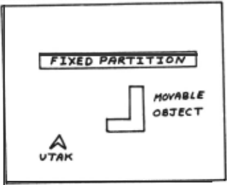
~·~ 'ltle sensory-motor capabilities of Utak
Utak can move in a straight line, he can grasp a movable object, and he can push, turn, and release a held object. He has five motor outp..~ts, only one of which is active at any one time . 'ltle visual sensory inp..1t is somewhat more realistic, consisting of 160 input lines fran 160 retinal receptors. Utak gets a bird's eye view directly down on his immediate environment as trough his eye were on a stalk. The retinal fields are arranged as follows: 64 in a central fovea, 48 fields each 4 times the size of a foveal field in an intennediate zone surrounding the fovea, and 48 fields each 16 times the size of a foveal field in an outer, peri!iJeral, zone. Each retinal cell registers a 3-bit graylevel, or integer in the range o-7, that reflects the ratio of object to total area in the part of the tabletop oovered by the cell's field. The oolour of an object is ignored. A set of 160 graylevels oonstitutes one retinal ilrpression. Cl:>ject oolours can be sensed via a tactile impression, which oonsists of the colours of the 8 adjacent squares to Utak.
The Utak simulaticn canputes a new retinal and tactile impressicn each time Utak rones to a halt. To cb so it superimposes the array of retinal fields on TABIE, centred en Utak's digital representation, and computes the graylevels directly from the TABIE array. An acticn by Utak will be reflected by a change in the retinal impressicn only if the digital representaticn of Utak or of an object held by him changes. ~re sophisticated visual sensory systems are easy to propose, but this cne is canputationally cheap and has sufficed so far. Figure 2 sh::Jws a retinal impressicn received by Utak oorresponding to the situation shown in Figure 1.
| 0 | 0 | 0 | 0 | 0 | 0 | 0 | |
| ' 6 | 0 | 0 | 0 | 0 | 0 | 0 | 0 |
| 6 | 1 | z. | 2. | ||||
| ~ | 0 | z. | 0 | ||||
| 6 | 0 | 1 | 0 | ||||
| 6 | 0 | 0 | , | ||||
| 6 | 0 | 0 | 0 | 0 | 0 | 0 | 0 |
| 7 | 6 | 6 | 6 | t | t | 6 | ( |
Hpre is a list of tasks, in English, which a competent organism-controller for Utak sh:>uld be able to handle.
- (i) "Go to the northeast corner"
- ( ii) "Go to the next room"
- (iii) "Go to the square"
- (iv) "Go round the square and return"
- (v) "Push the square into the northeast corner"
- (vi) "Push the square into the next roan"
- (vii) "Push the brick through the door"
- (viii) "Push the brick around the corner"
- (ix) "Push the L-shaped object into the next roan"
When a compass direction appears in the task statement this refers to Utak's <:Ml local orientation system, which need not coincide with the TABIEIUP orientation. It is initialized when the first retinal impression is received. Whatever directicn he is facing at that time becomes north in his orientation system. Among these tasks, the current system can handle (i) to (v).
1 Towards the design of ~ robot-controller
The purpose of this section is to present an awroach to the design and implementation of a robot-oontroller for Utak.
1·! 'Itle ~of an organism-controller
Any complete organism-controller for Utak must contain at least the following program steps. These can be stated here without specifying data structures or processes. All that is needed is a world model, a way to receive a retinal impression, and an action effector.
INITIALIZATION STEPS
- Set the current world model equal to some default world model.
- Receive the first retinal impression.
- Analyze the retinal impression into regions and borders.
- Interpret the regions in the retinal impression and identify the image of Utak in the retinal impression.
- Modify the default world model to be consistent with the interpreted retinal impressicn. .
- Accept a task and interpr.et it in terms of the world model. 'Itlis may require substantial modificaticn of the world model, for instance the addition of an object if one is mentioned in the task but no object is "visible" in the current retinal impression.
PLAN
- -=;-:-- Construct a plan to achieve the task, using the spatial planner.
THE ACI'ION CYCLE ACI'----
- s.- Test whether the task is complete. If so, STOP.
- Decide on the next action to take, by
examining the initial portions of the plan and the degrees of confidence associated with those parts of the world roodel close to the planned actions.
- Execute the next action and receive the next retinal impression.
l'EICEIVE
- Interpret the new retinal impression on the basis of the current world roodel, and modify the world roodel as necessary to make it consistent with the current retinal impression.
PIAN
- ~ Is the plan still viable? If so go to 8.
- Otherwise, re-compute all or part of the plan, as in step 7, and go to 8.
A task statement as required in step 6 is assumed to be presented as two parameterized world models, a starting and a goal world model. 'Ihe problem in step 6 is to reconcile the currently assumP.d default world model with the world model ;mnlied by the task statement. We make this assi.IJll>tion to circumvent the handling of natural language inp.1t.
l·~ ~ first approach to implementation
The world model consists of a collection of statements about the shape of the verge, the positions of objects on the tabletop, and the shapes of the objects. Each statement is to have an associated degree of confidence based on evidence collected from a series of retinal impressions. This degree of confidence is to be used in the -"CCCO''''''Clation process, to help determine to what extent old statements should be modified when new evidence is received. The statements give positions of end-points of lines and other spatial facts in terms of a Cartesian coordinate ~tern centred on Utak ~ A spatial problem lS to be solved by projecting all or part of the world model onto a screen- Utak's map-in-the-head then solving the problem there and translating the solution - the plan - back into the Cartesian coordinate system. At all times there is a world model and a plan, even though initially these may be simple defaults.
The implementation of these ideas was approached in the order given by the list of program parts in 3.1. Step 6, reconciling a world roodel with a task statement, was initially igoored on the hasis that simple path-finding problems that did not require reconciliation of two world models would suffice. Steps 1-5 were a~lished and then step 7, the int>lementation of a spatial planner, was tackled. It was found that current techniques for path-finding were oot really satisfactory and that an approach based on the use of the skeleton of a shape promised to be useful. This work is described in the next section.
3.3 Definition of the world model
The data structure for a world model consists of a tree of oodes linked hv relations. The root of the tree is a oode corresponding to Utak, called $org, which has one son, $floor, corresponding to the floorspace. The sons of $floor correspond to the isolated objects on the tabletop. The node N corresponding to an object may in turn have sons if the shape of the object is comolex and is best described in a hierarchicai manner.
A node corresponds to a shape on the tabletop and is a list consisting of the containing rectangle (the smallest rectangle aligned with the axes that contains the shape), the actual boundary shape as a circular list of straight-line segments, the shapes of any holes if present, and a sublist consisting of the relations between this oode and its descendants in the tree, if any.
By specifying the world model in this manner it is easy to modify it to reflect the notion of Utak or the notion of an object caused by the notion of Utak. All that has to be oone is to modify one relation. This tree representation can also be used to specify a complicated shape in increasing levels of detail.
3.4 Perception: accommodation to the first - - retinal i!IJ?resslOn - - --
When a retinal impression has been received it must be analyzed to find those regions which represent space and those which represent objects or verge. Then the object regions must be distinguished from the verge regions in an interpretation stage so that finally the world model can be modified to ac:cornrodate (explain) them. The next three sub-sections describe these operations (steps 3,4,5 of 3.1).
l·!·.! ~ and region finding
A region in the retinal impression is a connected set of retinal cells where all the cells have a zero graylevel, or else all have a oon-zero graylevel. A connected set on the retina is defined using edge-adjacency. TWo cells are edge adjacent if thev have an edge or par~ an edge in common. Thus diagonally adjacent cells are oot edge adjacent. A region is connected if, for any two retinal cells in the reqion, there is a chain of edge-adjacent retinal cells which starts at one of the given cells and
finishes at the other. 1·!·1 Interpreting the first retinal inpression
In the fCNea of the eye a retinal cell with zero graylevel corresponds to floorspace, and a cell with oon-zero graylevel, necessarily 7, corresponds to either an object, the verge, or to Utak himself. In the peripheral parts of the eye a retinal cell with zero graylevel may corresporrl to an area of the tabletop which is oot entirely floor space, and similarly one with a graylevel of 7 may correspcnd to an area of the tabletop which is oot entirely object or bourrlary.
In any one retinal bnpression the regions of zero graylevel are interpreted as floorspace. Since all floorspace is connected, if boo or rore discormected regions of zero graylevel appear in the retinal inpression the interpretation must provide that these are oonnected.
The non-zero regions are interpreted as either isolated objects or verge. 'Itlis is straightforward in two cases. If a non-zero region completely surrourrls a zero region, arrl is oot itself surrourrled by a zero region, then this is interpreted as the verge of the tabletop. If a zero region completely surrourrls a non-zero region then this latter region is interpreted as an isolated object with a high degree of certainty.
3.4.3 Accammodating the default world --- JOOdel to the first retlnal-- liipresSiof\ --
'Itle default world JOOdel with which Utak "wakes up" is the sinplest possible: a square floorspace centred on his position, ard containing oo isolated objects. After the first retinal inpression has been received and interpreted, this world ncdel must be modified (acoommodated) to be consistent
with this retinal impression.
First the interpreted retinal bnpression is examined for what restrictions, if any, the retinal inpression places on the actual dimensions of the containing rectangle of the $floor of the world ncdel. After the coordinate origin and containing rectangle of the $floor is fixed, other parts of the world JOOdel can be CX~~p.~ted. The next iten is to derive the actual shape of $floor. If none of the segments of boundaries of floorspace regions coincide with a retinal edge, or in other words the whole of $floor appeared within the retinal inpression, then the boundaries of the floorspaoe regions are taken as the shape of $floor. Otherwise, only parts of the "'hape of $floor appeared within the retinal bnpression. sequences of segments regions interpreted as strictly within the impression. 'Itlese are the of boundaries of verge, which lie current ·retinal Lastly, a node has to be created for each isolated-object region of the retinal impression, and added to the world ncdel. Given an isolated-object region, its containing rectangle, the offset of its coordinate systen from $floor, and its shape are all CCJ1llllted. 'Itle default worln JOOdel has nCM been accomoodated to the first retinal impression.
3.5 Perception: accamodation to - - subSequent ret1nal 1mpressiOns
Once a world model has been constructed that correctly interprets the retinal impressions received so far, it is used to facilitate the accommodation of subsequent retinal impressions. An overall view of this accommodation process will now be described. Given the decided-Q'l action, a ·predicted world ncdel is constructed, and from this a predicted retinal impression is produced by projecting the predicted world model onto an array structure topologically identical with a retinal impression . From the predicted world JOOdel a predicted retinal bnpression is <:atpJted.
In a "realistic" simulation where an element of randomness is allowed in the effect of an action the differences between the actual and predicted retinal inpressions may arise from two sources of uncertainty:
- New parts of the environment coming into view or old parts seen. at higher resolution;
(2) 'Itle action is oot as predicted. If only (1) is allowed then any differences must be explained by ncdifying the world ncdel. If only (2) is allowed the problem is to recognize what position in the world model could give rise to the actual retinal inpression and thus deduce what actually happened. Since the difference between the actual and predicted effects of an action will oormally be quite small the problem is one of <:atpJting the disparity between the two retinal inpressions, say by trying the positions closest to the predicted position. If the difference is too great for a disparity to be found then it becomes a pure recoqni tion problem to be a{:Proached, say, by matching features. If both (1) and (2) occur together then the problen is to find a match in the world ncdel for as much as possible of the retinal bnpression, thus proposing a new position, and then ncdifying the world ncdel to explain the remaining unmatched parts of the retinal impressicrt.
3.~ The spatial planner
This is the heart of the system, where path-firrling is done, where a plan for IIOVing an object is constructed, and where the initial task command is interpreted. Given an interpreted task description, the spatial planner uses the current world model as a database arrl produces a structured plan as output. If the current world model reflects the "real world" outside the organism sufficently closely, or at least models closely enough those parts of the \o.Orld rrodel required for this task, then a completely accurate execution of the plan will result in the successful completion of the task.
The spatial planner does not produce plans from the \o.Orld rrodel directly, but i rrlirectly via the screen, a 2-dimensional digital array. Consider a simple pathfirrling problem, "Go to the north east corner" for example. First the dimensions of a rectangular wirrlow which iocludes both the current position of Utak and the position of the destination are CXJI'Itlllted. Then the \o.Orld rrodel is projected through this windatl onto the screen and each square of the screen marked as representing space or with the name of the ooject 0\larlaying it. Then a pathfirrling algorithm is used (cf. section 4) to firrl a path from start to destination that only traverses cells representing space. ·
4 Path-finding and the skeleton of ~ ~nar shape
!·.!. Introduction to ~-finding algonthms
The problem is this. Given a description of shapes crt the Euclidean plane in terms of the Cartesian coordinates of points on the boundaries of the shapes and the lines between them, and aiven the coordinates of two points s and D outside all the shapes, describe a path from s to D that avoids all the shapes, if such a path exists. Further requirements are that the path should be reasonably close to being optimal, arrl that if an organism wanders slightly from the correct path, e.ither due to inaccurate IIOVement or to avoid a snall obstacle, it should be
easy to regain the correct path.
A path-firrling algorithm was iocorporated in the design of Shakey [12). It was based on the observation that in a cluttered space an optimal path between t\o.O points consists of a sequence of line
segments connecting extreme points of obstacles. Thus ooe starts with the extreme (convex) points on the obstacle boundaries and considers the set consisting of the lines joining the pairs of extreme points together with lines from the starting point s to the extreme points and with lines from the extreme points to the destination point D. Any line which intersects an obstacle is discarded, so that the remaining lines represent all the heuristic search is then used to find the optimal series of points connected by
"lines of visibility" in the situation. A lines of visibility from S to D.
Another idea is to project all the shapes onto a rectangular network of cells, the screen of section 3 for example, arrl convert the path-firrling problem into a pure graph-traversal problem. The screen is converted to a graph by inserting between every pair of adjacent or diagooally adjacent cells an edge of the graph, where each edge is assigned a lenqth of root2 or one according as its endpoints are diagonally adjacent or not. It is forbidden to traverse edges leading to cells that do not represent floorspace. The start and destination points are mapped onto cells S arrl D of the graph. The problem can rDW be restated as: find the shortest path from s to D along the edges of this graph. This can be done by an application of the A* algorithm of [8] using their function
f=g+h to evaluate inc<lll'(>lete paths.
Finally the skeleton of the shape of the empty ~e was considered. The initial attraction was that the skeletal graph contains only the topologically distioct paths between two positions. TwO paths are topologically distinct if neither can be continuously deformed into the other. The search for a path then reduces to searching over the topologically distioct paths. The choice points in the skeleton seem, intuitively, to correspond to the choices we have to make in navigating through obstacles. In addition there is a great deal of information associated with the skeleton which can be used in other spatial problems. The optimum path, when restricted to edges of the skeletal graph, is not in general the optimum path when no such restrictions are made; however, our initial concern was to compute any reasonable path, not necessarily an optimal one.
4.2 The skeleton ---
Blum, who called it the Medial Axis Function [2], was the first to introduce the skeleton of a planar shapP.. Sioce then it has been the topic of several
investigations [5,10,11,14,151 and has been called the distance transformation, the grassfire transformation, or the symnetric axis transformation. [3,4] has comprehensively analysed it and written about its p:>tential aR>lications to the description of shape in biology. Various definitions and algorithms foe computing the skeleton in a digital space are given in [16].
i·l Using the skeleton for ~-finding
Use of the skeleton of the shape delineated on a network prondsed to overcane rrost of the objections to the use of heuristic search for pathfinding.
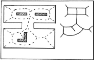
First assume that the start cell S and the destination cell D lie on the skeletal graph. Then a path from S to D along the skeletal graph is certainly a spatial path. In searching for a path through the skeletal graJX!, the junction cells and junction sets are the only places where a choice is needed. 'lb simplify this search the pathgraph, hcm:rrorJX!ic to the skeletal graJX!, is defined as folla..rs. The vertices of the pathgraph correspond to the junctions (cells or sets) of the skeletal graph, and an edge between two vertices of the pathgraph corresponds to the chain of cells in the skeletal graJX! between the corresponding junctions. A skeletal graph and its corresponding pathgraJX! is shown in Figure 3. Now all the topologically distinct spatial paths from S to D are found by using a standard graph traversing algorithm oo the pathgraJX!, with considerably less search than when the network of cells is searched directly. If the start S or destination D are oot on the skeletal gra~ then the nearest points to s and D on the skeletal graph, S' and D', must first be found.
2 Summary and conclusions
(a) We have explicitly described the features of the action cycle for a robot-controller; this has oot been done before.
(b) A spatial reasoning module is an ~rtant and essential part of any robot-controller. It makes plans for action on the basis of the current collection of hypotheses about the form of the environment. The second advance is the developnent of a new aR>roach to problems of spatial reasoning based on the use of the skeleton of a two-dimensional shape.
some interesting technical problems were uncovered in this aR>roach. One we call the rope-tightening problem. When you have found one reasonable path between two points, how do you tighten the path to the shortest p:>ssihle way? The other technical problem relates to elucidating the full details . for moving an L-shaped object through a doorway.
(c) 'rtlere have been several robot simulation programs written before; however this is the first to handle the movement and collision of two dimensional shapes. Our contribution is to use a combination of the Cartesian and the digital representations to simulate the motion arrl collision of objects on a tabletop.
We began this ?reject by asking what cam?Utational processes are required for spatial reasoning. Our answer, and, briefly, the conclusion of the paper, is this . Conputational processes incorporating algorithms for computing the digital skeleton of a planar shape may prove to be sufficient for the spatial reasoning of a robot-controller ·
Ackna..rledgements
'rtlis research was SUR>Qrted in part by the Natural Sciences and Engineering Council of Canada under grant oo. A-5552.
@inproceedings{ijcai1981p146,
  title     = {Spatial Problems for a Simulated Robot},
  author    = {Rosenberg, Richard S. and Rowat, Peter F.},
  booktitle = {Proceedings of the Seventh International Joint Conference on
               Artificial Intelligence, {IJCAI-81}},
  publisher = {International Joint Conferences on Artificial Intelligence},
  editor    = {Patrick J. Hayes},
  pages     = {758--764},
  year      = {1981},
  month     = {8},
  note      = {Robotics},
  url       = {https://ijcai.org/proceedings/1981/146},
}
TY - CPAPER TI - Spatial Problems for a Simulated Robot AU - Rosenberg, Richard S. AU - Rowat, Peter F. T2 - Proceedings of the Seventh International Joint Conference on Artificial Intelligence, IJCAI-81 PB - International Joint Conferences on Artificial Intelligence PY - 1981 SP - 758 EP - 764 UR - https://ijcai.org/proceedings/1981/146 ER -Copied
Machine-readable versions of this paper, for tools and AI agents:





