
Visual Understanding Of Hybrid Circuits Via Procedural Models
Proceedings of the Fourth International Joint Conference on Artificial Intelligence. Robots And Productivity Technology. Pages 742-747.
© 1975 International Joint Conferences on Artificial Intelligence
Abstract
A system of programs has been constructed to process the television image of a hybrid circuit. This system is capable of "inspecting" the circuit image regarding defects. To achieve this a procedural model of the circuit is developed. The computer "sees" the image and interprets what it s e es with the procedures in the model. In this manne r i t is able to determine certain important characteristics of the image in its view. It appears that this procedural approach can be useful to many domains of visual image processing and object recognition.
- Ejiri, M., Uno, T., Mese, M., and Ikeda, S. , "A Process for Detecting Defects in Compli- cated Patterns," Central Research Laboratory, HITACHI LTD., Kokubunji, Tokyo, Japan.
- Finin, T . , "Tracking Wires on Printed Circuit Boards," Working paper 52, MIT Artificial Intelligence Laboratory, October, 1973.
- Harlow, C. A., Henderson, S. E., Rayfield, D. A., Dwyer, S. J . , "Automated Inspection of Electronic Assemblies," unpublished manu- script, Image Analysis Laboratory, Depart- ment of Electrical Engineering, University of Missouri, Columbia . 745
- Hewe tt, C. , "Description and Theor e ti ca l Analysis (Using Sch emata) of PLANNER : A Language for Proving Theorems and M anipul a t- ing Models in a Robot," AI Memo No . 251, MIT Project MAC, April 1972 .
- Hueckel, M., "An Operator Which Locates Edges in Digitized Pictures," Stanford University, Artificial Intelligence Memo 105, Stanford, Ca. For a more recent and improved operator, see JOURNAL OF THE ACM, October (1973) .
- Krakauer, L., "Computer Analysis of Visual Properties of Curved Objects," MIT, MAC TR-82, Cambridge, Mass. (1971).
- Lozano-Perez, T., "Finding Components on a Circuit Board," Vision Flash 51, MIT Artificial Intelligence Laboratory, September 1973.
- Simon, The Sciences of the Artificial.
- Shirai, Y. , "A Heterarchial Program for Recognition of Polyhedra," MIT, AI memo 263, Cambridge, Mass. (1972).
- Winograd, T. , "Procedures as a Representation for Data in a Computer Program for Under- standing Natural Language," AITR 84, MIT, Cambridge, Mass. (1971).
- Winston, P., "Learning Structural Descrip- tions from Examples," MIT, AITR-231, Cambridge, Mass. (1970) .
- Yachida, M. and Tsuji, S., "Application of Color Information to Visual Perception," PATTERN RECOGNITION, 3, pp 307-323, (1971) .
- Yakimovsky, Y. and Feldman, J., "A Semantics- based Decision Theory Region Analyzer," Proceedings of the Third International Joint Conference on Artificial Intelligence, Stanford, Ca. (1973) .
References were extracted automatically from the PDF and may contain errors.
Full text extracted automatically from the PDF; figures, tables and equations may differ. The PDF is the version of record.
1. Introduction
One stage of the manufacturing process of hybrid circuits which is not automated is a visual inspection of these circuits. This paper describes the development of a system to demonstrate automa tion of visual inspection by using the techniques of computer vision, and in particular, the prin ciple of procedural models.
Hybrid circuits are built on a rigid, insu lating substrate, generally some ceramic material. Resistors and conductors are painted on using paints, which, when dry, have different resistivities. Transistors, capacitors, and integrated circuits are then mounted with either solder or glue. Finally, wires are attached which make the connection to some sort of holder.
In hybrid circuits factories, the visual in spection is generally performed by peering through mi croscopes. One major purpose of the human in spectors is quality control. It is desirable to determine not only if a circuit is defective, but why it is defective so that corrective measures may be taken. Another important use for visual inspection is to detect defects in partially com pleted products so that the defective part may be rejected early in the assembly process, before it has become part of a much larger and consequently
more expensive product.
The inspectors check for missing, misplaced or misoriented parts, bad solder bonds, etc. This in spection has not been automated previously because the manufacturing process introduces numerous ir regularities in normal circuits. For instance, in the soldering process the solder rosin may flow in unpredictable ways, discoloring the substrate and producing extraneous edges.
*Research supported by the Joint Services Elec tronics Program (u.s. Army, u.s. Navy, u.s. Air Force) under Contract DAAB-07-72-C-0259.
VISUAL UNDERSTANDING OF HYBRID CIRCUITS VIA PROCEDURAL MODELS*
R. T. Chien and w. Snyder
Coordinated Science Laboratory University of Illinois at Urbana-Champaign Urbana, Illinois 61801 u.s.A.
The first objective of the development of the circuit inspection system was to provide a contex t in which to examine the principle of procedural models. The system provides this context in three different ways:
- Inspection provides an application of the top down approach to vision, and of the procedural models which incorporates this approach .
- The problem of re-training the system for i n spection of varied circuits provides an exerc i se in automatic generation of procedural mode ls .
- The fact that identification of certa in circuit components may be dependent on the identity of neighboring components provides an instance t o make use of the power of procedural models where by one model may call another model for assistance.
Another objective was to develop a system which could run under "reasonable" assembly line conditions. Since hybrid circuit assembly lines have considerable accuracy in positioning, a cer tain amount of predictability was assumed in loca tion of the circuit. It is also reasonable to assume a degree of control over direct lighting,
but control over ambient light could not be assumed .
2. Basic Characteristics of the System
The heart of the system is a procedural model. This model consists of the overall circuit model and several component models. The system under stands the characteristics of each type of compo nent via the component models; while it under stands the topological and structural relationships
via the circuit model.
The operator positions a circuit under the lens of the television camera and starts the sys tem which takes five pictures: two grey-scale pictures with the lights turned at different angles, and three with color filters. These five pictures are stored on disk files for convenient later reference. The operator then uses graphics to specify the
circuit details.
The output of the initialization phase is a model for the entire circuit. This model includes a data structure and a control structure in combi nation which when compiled and loaded become the inspection phase of the system.
In the initialization of the system another picture, representing the hue, il computed from the three color pictures and stored . Another pic ure, the ''masked difference" picture used in the wirefinding algorithm is also computed and stored at this time .
Since wires can obscure other components, they must be identified prior to any other components. Thus, wires are located first and their locations remembered for the other component models to check .
3. Procedures as Models for Visual Objects
This section contains a discussion of some of the problems associated with the creation and use of models for visual objects and presents the con cept of "procedural models." When using such mod els, recognition of an object becomes equivalent to executing the appropriate model. Instead of having a multiplicity of models for objects stored in a data base and some general purpose program for choosing and using these models, the models them selves are programs.
Procedural Models in the Circuit Inspection Problem
In the analysis and inspection of hybrid cir cuits, procedural models can become involved at three different levels: in component recognition, that is, answering the question "is X a resistor?" . in circuit recognition, answering "is this circuit what it should be," and in a combination of these, component/circuit identification with a symbolic model. (In this section, program examples will be presented in a meta-language for ease of reading. In fact they are not implemented in this form.)
Component Recognition
In a resistor model data is passed in the form of pointers to picture points and what the inten sities should be at those points . Resistors are the simplest of this type of model. Other more com plex models make use of backup, color information, r egion growing, etc.
Another more difficult problem arises when the appearance and/or location of the component cannot be known in advance. In that case, the model must first locate the desired object and then inspect it, or, in failing to successfully locate it, report it missing . This problem arises in the hybrid circuit inspection system in the case of wires.
Circuit Verification
The second type of model is similar to the first, in that the circuit is described in terms of a coordinant-based model. In this case, the cir cuit model might look like this:
PROCESS CIRCUIT(X)=BEGIN
%x is assumed to point to a list structure describing where components should be located. The process FINDCOMP analyzes this structure to select a descriptor and returns it%
DECLARE OWN Y;
Z+
RTEST:BEGIN
DECLARE BACKUP TRUE ;
Y+- FINDCOMP(RESISTOR,X);
IF Y EQL FALSE THEN LEAVE RTEST WITH TRUE;
IF NOT RESISTOR(Y,IMAGE) THEN FAIL ;END;
IF Z EQL FALSE THEN BEGIN TYPE('DEFECTIVE RESISTOR AT'); TYPE(GETPROP(Y,XCOORD),',',GETPROP (Y,YCOORD));END;
This simple process uses backup in a limited
END
form to verify all the resistors on a circuit board. The list containing the desired locations of the resistors is passed as an argument, X. FINDCOMP finds an entry on X which has been marked as describing the location of a resistor. FINDCOMP returns FALSE when it cannot locate any more resis tors . If RESISTOR locates a defective resistor, it marks the property list of its argumen~ Y, with the coordinants of the defective resistor and re turns FALSE. If RESISTOR returns TRUE, then the conditional IF NOT RESISTOR fails, and control backs up to the FIND to locate another component to try.
Symbolic Representation of Circuits
The final form of procedural model in the case of circuit analysis makes use of a symbolic or schematic representation for the circuit and performs the analysis in terms of that representa tion. In this case, the problem is: given a sche matic representation of the circuit, one in which the components are simply described as "Rl" for some resistor, etc., and given an image of a real circuit which implements the schematic representa tion, perform the correlation between the compo nents of the image and the symbols in the schematic representation.
Let us consider such a representation of the circuit shown below.
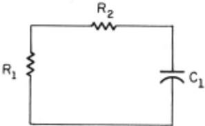
PROCESS SYMCIRCIT+BEGIN DELCARE BACKUP TRUE; Rl+-'FINDREGION(DARK,O) ; !find any old dark region FAILTEST(Rl); !can't find one, quit IF RESISTOR(Rl) THEN Yl+-FINDREGION(ADJACENT, Rl) ; IF CONDUCTOR(Yl) THEN R2~INDRE�ION(ADJACENT, Yl) ·. IF RESISTOR(R2) THEN YJ~INDRE�ION(ADJACENT, R2); IF CONDUCTOR (YJ) THEN Cl~INDRE�ION(ADJACENT, YJ); IF CAPACITOR(Cl) THEN YS~INDRE�ION(ADJACENT, Cl); IF CONDUCTOR(YS) AND ADJACENT(YS,Rl)THEN SUCCEED;END
This process embeds the structure of the cir cuit into the process without resorting to da ta structures. First, the assumption is made that the dark region found is Rl, and search is made for regions bordering Rl which might be the conductor leading to R2 . In case of failures, the process backs up, changes its hypothesis, and continues. Some of the intricacies which could easily be added include a more sophisticated search, remembering partial results, rather than this essentially depth-first search.
A reasonable approach to the problem of gen erating procedural models is to allow the system to learn new models by examples. This is the ap proach taken in the system implemented and describ ed in the next section. The model which the system generates is a process description for identifying the various components and checking that those com ponents are properly located within reasonable assembly line tolerances. The model is them com piled, and can be used to check for defects on othe r, similar circuits.
4. Component Models
Resistors
Resistors are typically so dark as to have no significant color but can be distinguished easily by the f act that they are so very dark. They usually (but not always) have borders which are straight lines . They border either conductors or the substrate, both of which are bright regions and thus (except when obscured by wires or pads). resis tors have easily distinguished borders.
The setup phase , when told where a resistor is located checks the intensity of the region and locates the borders. It then sets up the model of the circuit it is building to look in the appropriate places when it is inspecting circuits.
The type of capacitor for which the system was developed has two metal plates at either end of a region of homogenous intensity.
First the central region of the capacitor is located and its color determined. Then, an out ward scan is made using the Hueckel [6] operator in an effort to locate the end plates. These metal end plates suffer from the same problems as wires, ref l ections . End plates, however, are parallel to each other, thus when the edge detection operator locates an edge, it verifies that it is parallel to a corresponding edge on the other side of the capacitor . In this way, improperly mounted capac i tors can be detected, as well as those that are missing or dirty.
Because wires are flexible and can be bent in a variety of different shapes while maintaining good contact with both lugs, their location is unpredictable. In addition, they are three dimensional in that they may pass over other compo nents, thus obscuring those components from view.
Wires are "shiny." (They are essentially convex mirrors . ) The shiny property of wires can be described as follows :
- Wires have no characteristic color; their color is totally dependent on incident light and angles of refl ection.
- Depending upon the angle of the wire, light source, and camera, a wire may possess highlights (direct reflection of light source into the camera) and nulls (reflection of a very dark region into
the camera). A wire thus typically appears as a set of long, thin bright areas running in a more or less linear fashion from one lug to another . A highlight on a wire may pass over a portion of the substrate which is white, and effectively merge into a region of uniform (high) intens.ity .
An interesting characteristic of highlights is that they move when the viewing angle is changed , or the light source is moved. Thus one way to identify a highlight is to note its motion when the light source is changed.
Since all the components are generally ir regular and noisy, identification of an object whose sole characteristic is that it reflects these irregularities and noise isn't easy . However, since we are given the starting and ending points of the wire with reasonable precision, it is pos sible to detect it. The visual properties describ ed suggest the following algorithm: first, a "masked difference" picture is generated from two pictures taken with different lighting angles. A new picture is created where each point in the new picture is equal to the absolute value of the difference of corresponding points in the two pic tures. In this difference picture, the regions which are most significant are those in which the illumination has undergone a large change. This effect is maximum in the case of nulls, highlights , and shadows. The difference picture is then used as a mask to accentuate the highlights.
Three routines, WIREFI, WIRE, and MAKEWIRE , call each other in the wire-finding process . The flow of control is shown in the figure below.
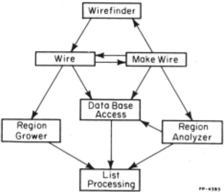
WIREFI sets up the desired end points between which there should be a wire.
WIRE searches between those end points and off at different angles, using either no a-priori information or possibly using "hints" passed from MAKEWIRE to direct its search. It calls a region grower to locate regions and makes tentative deci sions about whether or not a region might be part of a wire. When its search is completed, WIRE ca lls MAKEWIRE .
MAKEWIRE uses higher level knowl edge to oper ate on the list of regions passed from WIRE to decide wh ether or not the information given is sufficient to identify a wire. If there are large empty spaces between regions, it can call WIREFI to examine these spaces in more detail.
One interesting problem which arises in the region analysis is that of finding the extrema of arbitrary regions. It is computationally unreason able to compare all points on the boundary of a region, two at a time. A search algorithm was developed which usually converges in three itera tions and returns those two po1nts on the boundary which are a maximum distance apart.
Performance of the System
Though the system was written in BLISS, many LISP features were carried over. For example, the functions CAR, CDR, etc., and garbage collection were implemented in BLISS for the sake of conve nience. The use of lists allows for easy and rapid implementation of fairly complex data structures. In exchange for this ease of developmental pro gramming, one pays a high price in efficiency.
Because the time required to perform the verification depends so strongly on the complexity of the particular circuit being analyzed, it is difficult to estimate. The most time consuming part, the wire finding, with its accompanying region growing, takes just under a second for an average wire, longer for longer wires.
The accuracy of the system in detecting defects is also a function of the training proce dure. Since the system only looks where it is told to look, it is always possible to invent a type of defect which any particular model could not detect. In general, a large class of defects could be detected by checking the wires, the resistors, and the capacitor.
@inproceedings{ijcai1975p118,
  title     = {Visual Understanding Of Hybrid Circuits Via Procedural Models},
  author    = {Chien, Robert T. and Snyder, W.},
  booktitle = {Proceedings of the Fourth International Joint Conference on
               Artificial Intelligence, {IJCAI-75}},
  publisher = {International Joint Conferences on Artificial Intelligence},
  editor    = {Patrick Winston and Carl Hewitt},
  pages     = {742--747},
  year      = {1975},
  note      = {Robots And Productivity Technology},
  url       = {https://ijcai.org/proceedings/1975/118},
}
TY - CPAPER TI - Visual Understanding Of Hybrid Circuits Via Procedural Models AU - Chien, Robert T. AU - Snyder, W. T2 - Proceedings of the Fourth International Joint Conference on Artificial Intelligence, IJCAI-75 PB - International Joint Conferences on Artificial Intelligence PY - 1975 SP - 742 EP - 747 UR - https://ijcai.org/proceedings/1975/118 ER -Copied
Machine-readable versions of this paper, for tools and AI agents:





