
Design of a Low Cost, General Purpose Robot
Proceedings of the Third International Joint Conference on Artificial Intelligence. Robot I mplementations. Pages 324-335.
© 1973 International Joint Conferences on Artificial Intelligence
Abstract
This paper reports on current work at the University of California at Berkeley whose goal is the design and implementation of a relatively inexpensive, but versatile, experimental, computer-controlled robot suitable for use in either a research or educational setting. The Berkeley robot, dubbed Jason, is nearing completion and hardware tests are now being conducted. Jason is designed so as to permit it to navigate and manipulate simple objects in a real-world environment. It uses a variety of sensory-motor and communication devices; among these are an ultrasonic range, motion, and material detector, an isolated-word speech recognizer, a limited speech synthesizer, six inexpensive proximity detectors, and two arms for simple manipul ation, all of which are mounted on a platform chassis. The robot vehicle is remotely controlled, using radio telemetry, by a time-shared, virtual memory, HP-3000 mini-computer, utilizing adaptive learning programs. Jason was primarily constructed to explore: (1) how an inexpensive, real-world robot system might be designed, and (2) what problems a robot "encounters" and "creates" while performing tasks in a real-world environment populated by humans. The results of this research will hopefully enable us to design and build better (more reliable and safer) robots at a modest price that are still capable of performing a variety of interesting and useful tasks. Key Words and Phrases Robots, Artificial Intelligence, Problem Solving, Learning, Real-World Environment. CR Categories 3.62 (Learning and Adaptive Systems); 3.64 (Problem Solving); 3.69 (Miscellaneous-Robots).
- C.A. Rosen, "Robots, Productivity, and Quality," Proc. of the 1972 ACM National Conference, Boston, Massachusetts, August 14-16, 1972.
- L.S. Coles, ed., "A Preliminary Design for an Industrial Robot," Department of Electrical Engineering and Computer Sciences, The University of California at Berkeley, March 15, 1971.
- S. Pappert, General Turtle, 545 Technology Square, Cambridge, Massachusetts.
- N.J. Nilsson, "A Mobile Automation: An Application of Artificial Intelligence Techniques," ~roc. o~ the First Internati~~t__CQnference on Artificial Intelligence, pp. 509-520 (ACM, May 1969).
- - P.H. Winston, "The MIT Robot," in Machine Intelligence 7, ed.
- J.A. Feldman, et al., "The Stanford Hand-Eye Project," Proc. of the First International Joint Conference~rtificial Intelligence, pp. 521- 526a (ACM, May 1969). IJCAI
- H.G. Barrow and G.F. Crawford, "The Mark 1.5 Edinburgh Robot Facility," in Machine Intelligence _l, ed.
- E.R. Berlekamp, Algebraic Coding Theory, (McGraw- Hill, New York, 1968).
- L. Kay, "Evaluation of the Ultrasonic Binaural Sensory Aid for the B 1 i nd," Eva 1 uati on of Sensory Aids for the Visually Handicapped, National Academy of Sciences, Washington, D.C., 1972, pp. 85-94.
- A.R. Lazzara, "LED Photoelectric Controls -What are they?", Scientific Technology, Inc., Mountain View, Cal if. 335 [ll]
- A.L. Samuel, "Some Studies in Machine Learning Using the Game of Checkers, II: Recent Progress," IBM Systems Journal (Nov. 1967), pp. 601-617.
- E.L. Lawler, "A Procedure for Computing the K Best Solutions to Discrete Optimization Problems and Its Application to the Shortest Path Problem," Management Science, Vol. 18, No. 7, March 1972.
- M.H. Smith, "A Learning Program which Plays Partnership Dominoes," Communications of the ACM (August 1973).
- N.J. Nilsson, Problem Solvinq Methods in Artifi- cial Intelligence, (McGraw-Hill, New York, 1971).
References were extracted automatically from the PDF and may contain errors.
Full text extracted automatically from the PDF; figures, tables and equations may differ. The PDF is the version of record.
I. Introduction
The field of robotics is rapidly becomin9 an impor tant topic of research and study. This is due in part to the possible widespread applications of robots to tedious, repetitive, or dim9erous tasks. While robots with one or two highly sophisticated sensory devices have been extensively investi(Jated, it is only recently that more research is · being extended to s.vs tern design and integration of a robot having a relatively large number of sensory-motor devices.
Current work at the University of California is being carried out with the objec'tive of designing and building a· comparatively inexpensive, but general purpose experimental ' computer'-controlled robot. The Berkeley robot, dubbed Jason, is intended to be capable of operating in a real-world environment populated by human beings. For ·the sake of this investigation, the real-world environment is taken to consist of the Berkeley Campus at large~ especially the second and third floors of Co~y Hall, the engineering building on campus. When Jason is fully operational, it will not only be used for research, but also as a teaching aid for young children at the Lawrence Hall of Science, as well as for public demonstrations.
This paper is divided into four sections. The first section explores the background and rationale of the project. The second section presents a brief descrip tion of Jason itself. The third section briefly mentions the need for safety precautions. Finally, the last section summarizes and draws some conclusions about the Berkeley robot project.
II. Background and Purpose
Considerable effort has alreadv been directed toward the development of automatic mach.ines for factories, farming, transportation, and so forth. Yet such machines have been carefullv contrived to deal with highly constrained environm.ents. The addition of jus t a few advanced sensors and a small amount of computa tional ability might enhance the versatility of such machines manyfold.[l] For example, advanced, general purpose robots could carrv out diverse real-world tasks such as the following: ( l) Space and Underwater Exploration~ (2) Teaching-Aid in Schools, (3) Gardening, (4) Harvestina, (5) Bank Security Guard, (6) Warehouseman, (7) Inexpensive Hospital Aid (8) Traffic Controller, (9) Minin(J Surveilance, (10) Street Cleaning, (ll) Deeo Sea Farming, and (12) Office-building external window washer.
In fact, any task which requires only "closed thinking", i.e., a task constrained by a specified goal and set of operators, could be performed by an advanced robot. Furthermore, several robots, carrying out different tasks, could all be supervised by the same time-shared comouter sys tern. These robots, ~tith various interchangeable sensory-motor devices and computer programs for different tasks, would be able to carry out a wide variety of jobs for a much smaller cost than the exnense of developing special purpose automation for each task.
In the field of industrial robots, a careful survey of the potential marketing opoortunities has been made in Coles (pp. 58-74)L2]. In the area of educa tion, Papert[3] has made considerable' strides with his "turtle" robots.
For this reason, considerable research in robots is currently being carried out at major centers such· as SRI[4], t~IT[5], Stanford University [6], and the University of Edinburgh[?]. SoPhisticated automata have been designed and built to operate on table-tops or in carefully controlled environments. However, when trying to perceive and model the real world, AI resear chers in the field of robotics have traditionally focused their attention on the television camera as their major source of sensory data. Consequently, a great deal of effort has been directed toward the com putational processes needed to make "sense" out of the TV camera image whenever it depicted a typically cluttered, real-world scene. These processes have tended to become increasingly expensive,·even when the environment is ingeniously constrained to capitalize on the idiosyncrasies of the TV camera. The time to process a single complete scene has taken upwards of ten minutes at SRI using a high-po~tered computer facility. Obviously, a low-cost robot cannot afford to adopt this approach.
Our own research departs from previous work in that it attempts to incorporate the output of a variety of inexpensive sensors to nrovide more efficient perceP tion of the real world, when tailored to simple navi gation and manipulation tasks. Under these conditions such sensors are not only computationally cheaper, but are more reliable, since different sensory modes can mutually reinforce and corroborate one another. If binary sensing-decisions can .be made in real time, the possibility for dynamically altering a precomputed path during navigation (to compensate for an unantici pated obstacle) can become feasible.
In an effort to obtain further insioht into the problem of ooerating a real-world robot, our experi mental robot project was begun in April of 1972. Special emphasis was placed on designing a small, low cost, but versatile mobile robot capable of oerforming a wide variety of tasks, such as exploring fairly un cluttered environments and manipulating small objects. Therefore, Jason has been provided with a ~tide range of sensory and data-gathering input devices, none of which is very sophisticated in itself or imposes severe comoutational renuirements on the control computer, but all of wh1ch could be well integrated. Figure 1 gives an overview of Jason in its proposed form.
Jason has the following sensory/motor and interface devices:
- an ultrasonic range and material detector;
- two simple arms with clasping grippers;
- proximity sensors (used in place of microswitch
bump detectors);
- a 30 to 40 ~10rd speech recoanizer;
- a limited speech -synthesizer;
- optical counters for measuring wheel distances traveled by the vehicle;
- ( 7) a robot chassis nowered by two 1 /4-horsepower oermanent-magneti c motors; and,
- a ten-watt nower output, 467-megahertz radio communication network.
A time-shared, virtual memory, Hewlett Packard 3000 computer with appropriate soft~tare serves as Jason's control computer. The HP-3000 is located at the La~1rence Hall · of Science and controls the robot vehicle by means of radio telemetry. One of the advantages of a time-shared computer is the nossibility of running several similar robots (olanned for the near future) under the same executive: nrooram, so the oroblems associated ~lith multi.,.robot coooeration and communica tion can be investigated. However, it should be stressed that neither Jason's robot vehicle, the above mentioned sensory /motor devices, nor the comnuter pro grams are very sophisticated. They are not intended to be. Rather, the puroose of the nro_iect is to study the problems in designing a simolified and inexpensive robot system that integrates a varietv of sensory/motor devices.
When Jason ~tas designed, one of the important con straints was to minimize the cost of construction. Throuohout this pal)Cti" · we shall stress the economical design and the simplicity of the sensory/motor devices. Although the labor involved was considerable, the actual cost of parts, including the radio network, but not the computer or its interface, was well under $2,000. Yet Jason cannot be thought of as a toy. It is capab 1 e of carrying out a ~1ide variety of tasks, even though thev may be elementary by human standards. It is precisely this oeneralitv in the class of tasks which is the kev to the project'. ·
III. A Descriotion of Jason
Jason consists of three major subsystems: (A) the chassis, (B) communication and sensory/motor devices, and (C) software control nroorams. The robot vehicle transports Jason through its environment in a precise manner. Reasonably accurate movement is needed to avoid either the ranid accumulation of errors that would othe~tise lead to bumoino into walls, etc., or highly inefficient behavior in . carrving out the simpl est of tasks. A varietv of sensorv devices are needed to ouarantee a rich bas'e of inform-ation about the ex ternal environment so that reliable decisions can be made. The robot software has the task of integrating the output of these sensors so as to construct an accurate model of the environment and harmoniouslv control the various sub-systems. ·
A; The Robot Chassis
The first major subsystem is the robot chassis. It consists of t110 seaments: the actual mechanical wheel assembly and the on-board, electronic logic ~thich con trols the vehicle's wheel assemblv. The chassis (see Figure 2) by itself weighs about 125 nounds (not inclu ding the sensory/motor devices). Its dimensions are aoproximately 2 feet by 2 feet and it cost about $200 for parts, including electronics, but not including labor and overhead.
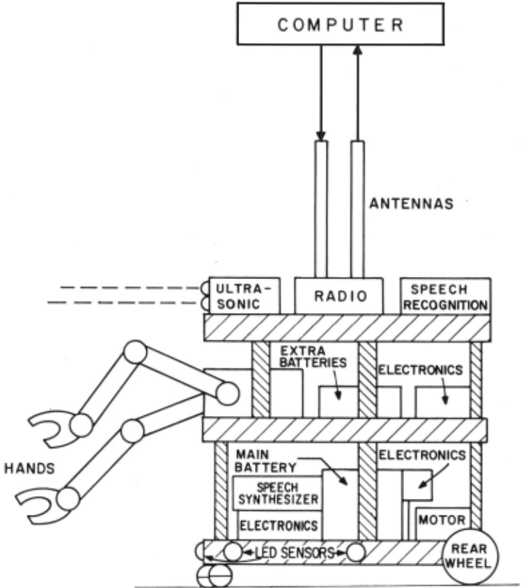
Figure 1 - Overview of Jason
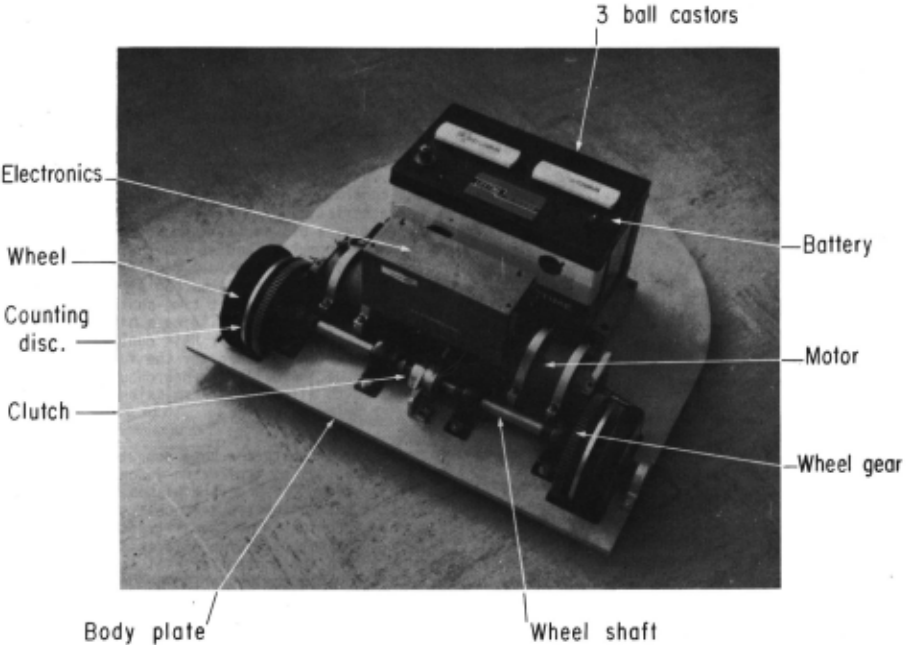
The chassis was designed to have the following mechanical properties and subcomponents:
- Each of the two six-inch diameter, rubber covered, rear wheels is 9ear driven by a seoarate l/4 horsepower, permanent-magnetic motor.
- The two rear wheel surfaces are mechanically around to within .001 of an inch in circumference to insure accuracy in rolling movement.
- A magnetic clutch is utilized to insure that both rear wheels rotate together when the vehicle is moving in a straight-line path.
- The front of the chassis is supported by three one-inch diameter steel balls in the shape of an equi lateral triangle. This design firstly eliminates torque problems otherwise associated with turning, and secondly, supports the chassis in the event that one (or two) ball(s) slides into a crack in the floor or pavement.
- Two five-inch discs with two rows of 60 holes drilled around their perimeter are mounted on the wheel shafts. When used with optical encoders, they enable the robot to determine the distance and direc tion of travel quite precisely. The vehicle has a maximum linear accuracy of one-quarter inch.
- Finally, the chassis is of rugged design with 3/4 inch diameter steel wheel shafts and a l/2 inch thick aluminum body plate.
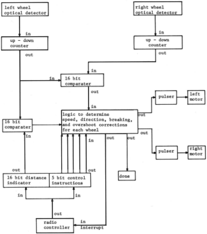
The second seoment of the chassis, the basic control logic (electronics) subsystem, is shown in Figure 3. It has the following oroperties:
- The logic circuit is designed such that the computer program is only required to load a 5-bit command and a 16-bit location counter (to indicate the distance the vehicle is to travel).
- The looic circuit then determines (i) th& correct speed· (based on distance to be traveled), (ii) direction of travel, and (iii) if any overshoot has occurred (if so, it is corrected by the looic circui't automatically).
- The logic circuit, together with the clutch, insures that both rear wheels rotate together.
- If the robot, for some reason, cannot move to the desired location, e.g., it encounters an obstacle, an interrupt is generated and transmitted to the computer.
- The electronics controls the motor's speed by providing pulses to the motor; this conserves batte~y power.
- Braking is done electronically by placin9 a variable load (amount determines the rate of braking) across the terminals of each rear motor.
- The maximum distance it can travel in a straioht line without additional computer commands is 120 feet.
- Finally, the robot vehicle's motors, control electronics, and sensory/motor and on-board communica tion devices are powered by an 83 amp-hour lead-stora9e battery, which is easily recharged as necessary. Other smaller batteries are installed on-board for special purposes. For example, one battery pro vi des negative 12 volts to the speech-recognition detector and
orovides for fail-safe operation in the event of a main battery power failure. ·
The vehicle has already been built and has proven satisfactory and reliable in manual tests. Actual computer tests are not yet nossible because our FCC approval for the assi9ned robot communication frequency is still pending at the time of this writing.
B. Communi cation and Sensory/~~otor Devices
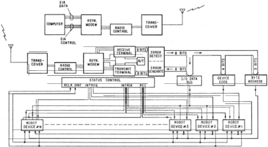
The second major subsystem for Jason consists of its sensory/motor devicesand a 2-way, half-duplex, radio communicatioo controller. (See Fiaure 4). The communi caUons_.col'1tro11.er·p-rovides .a central distribution sys tem for reception and transmission for Jason's perpher i ca 1 devices and the host .comnuter:.. The communication system consists of: (1) a standard serial terminal in terface, (2) a hi9h-soeed asynchronous modem (up to 2400 baud max., depends on radio), (3) two ten-watt power output, F~1 modulated 467 ~1Hz transceivers, (4)an antenna system, (5) a communication controller on the robot vehicle, and, (6) Jason's Perpherical devices.
- Radio Network. Because it was desirable to make the controller as independent as possible from the characteristics of any one· comouter, the controller appears as a bit serial asynchronous data terminal to the host computer, and as a byte-serial interface to any of Jason's perpherical devices. Thus standard serial terminal interfaces can be used; this allows easy interfacin9 to· most time-shared computers with out the hiah cost of bui1dino a hiahly specialized interf~ce. · Also, either hal~ dupl~x (as used presently) or full duplex (planned for the future) transmission can be done. Finally, asynchronous operation is required to allow for transmission interruption by a higher priority device.
Initially, both the host computer interface and the communications controller on Jason will be in the receive mode. If a device wishes to transmit, it must first issue an interrupt reauest to the controller. If no higher priority device is transmitting and the con troller is not receivina data at the time (receive- lock mode), then the controlier will issue an interrupt acknowledqe to the device. The controller will then switch the transceiver to transmit mode, wa)t approxi mately lOOmsec for the carrier to reach the transceiver at the computer end and for the computer soft~/ are rou tine to lock its transceiver to the lock- receive mode, queueing any further transmission requests.
Transmission from Jason to the computer may now be9in. If a higher priority device requests to trans mit, the current transmission ~Jill be terminated imme diately and its interrupt acknowledae line will be made false (each device has its own interrupt request and interrupt ackno~1l ed9e 1 i nes). The i nterrunt acknow ledge for the higher priority device will then be made true. To indicate that the previous transmission was interrupted, a device-interrupted pulse (500nsec) is issued to all devices. Furthermore, the ambiguity of a device thinkina that it has been interrupted when in reality it caused the interrupt, is avoided by not havinq the device look at the device- interrupt control line for 750nsec after receiving interrupt acknowledge. Finally, each interrupted device will make a new inter rupt request and ~Jill then hold the interrupted data in its buffer until it can be transmitted. All interrupt requests are handled in an ascendin9 priority order until all interrupts have been cleared.
If the transceiver is in the receive mode (normal default mode when not transmitting) and carrier detect goes true; indicating that the computer end has turned on its transmitter, then the robot vehicle's controller will go into lock-receive mode (reception starts and interrupts are no longer acknowledged). After the controller reaches lock-receive mode, it will search the input data stream for the first occurance of a "control" byte. The present of a control byte will start the controller's receive sequencer. The receive sequencer first loads the control byte into a error detection data register, then waits for the reception of the next byte, which is a error-checking byte. This byte is loaded into the error-detection error-byte register. The sequencer then tells the error detection logic to start processing. The error logic will signal the sequencer when error checking is completed. The tested byte is now loaded into the device code register and the byte count register if it was a control byte; or it is loaded into the output data bus register if it was a data byte. \~hen a con trol byte is received, the device code line, byte select lines, and 'REC' line are set up for the device which is to receive the data. The 'REC' line plus the correct device code on the device-code lines ·is the proper indication to a device that it is receiving data; hote that only data can be passed to a device via the 8 bit I/0 bus, and not control bytes. If an error occurs during reception, an error flip-flop is set and remains set until the end of the reception-sequence. The error flip-flop's output is passed to all devices. Since the system will be initially half-duolex, the computer cannot be informed that an error has occurred until the reception sequence is completed; only then may a special device transmit the error condition back to the computer.
The error code used for error checking is a form of double error correcting hamming code. The process involved in generating the error code is discussed by Berlekamp in [8, Chap. 5]. Error coding generation is done in hardware on the controller and in software on thg c9mp~te[· It involves calculating the polynomial (x +x +x +x +1) of the parity check matrix formed from the serial data !nput. A root of the polynomial is assumed to be (x +x+l) and was used in developing the hardware and software. The resultinq error code is then transmitted after the data. On · reception, the data is first passed to another error-code generator; the resulting error code generated is then compared with the error byte received after the data byte. In the present version of the system, no automatic error correcting is done in order to limit the initial expense.
- Description of Devices. The sensory/motor and communication devices utilized by the robot are summarized be 1 o~t:
- (a) Arms -- Jason will have two hands of the simple clasping type. each with three degrees of freedom. These have been roughly designed, but not yet construc ted. The arms are not intended to be fast, accurate, or heavy-duty. They will be lightweight and will pick up lightweight boxes, push buttonshand push or pull simple objects.
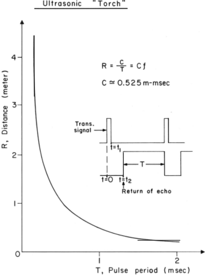
- (b) Ultrasonic Detector-- a narrow-beam, frequency modulation, echo location system in the form of a "torch" is utilized[9]. Ultrasonic waves which cover a wavelength range of 2.5 to 5mm are used. Bandwidth compression (achieved by continuous wave, frequency modulation transmission) is needed since the useful auditory bandwidth is approximat~ly 5 KHz while the bandwidth of the information carrier in air using
ultrasonics is about 50 KHz. Thus, ultrasonics nrovide an overall reduction in information transmitted of 500,000 as compared with vision. The ultrasonic "torch" sensor sweeps downward from 100kHz to 50KHz. The pitch of the return echoes, which are converted to audio tones, are orooortional to the ranae of an object (each 300Hz change corresponding to about 1 foot, see Figure 5). The ouality (timbre) of the echo indicates the type of surface from which the echo was reflected, hence indicatina the nature of the object . Because soft objects reflect poorly at higher fr~quen cies, these echoes build in strenath as the sensor sweeps down. By digitizina the pitch (the width of the echo pulse period) and the relative echo strength (by taking 4 to 8 samples as the sensor s~teeps down ~tard), it is possible to determine the range with an accuracy of +10 percent and to obtain textural infor mation. Unfortunately, the angle from which the ultra sonic beam is reflected from an object affects echo strength, and thus appears to change textural infor mation, e.g., a hard object at an angle such as a slanted wall could look to Jason like a soft object directly in front of the sensor. Semantic information is needed to resolve such ambiguities.
Up to three objects at different range and direc tions within the field of vievt may be resolved when the torch is held stationary, i.e., multiple tones or "chords" are possible with multiple objects. Dynamic conditions are ·more complex. However, exnerienced blind persons using such a device are capable of:
- (i) identifying objects such as the following: smooth poles, ~tindows, bushes, trees, parking meters, cars, railings, street sians, doorways, moving pedes trians, traffic lights, mail boxes, rising steps, grass, plaster walls, etc.;
- (ii) walking up and grasping a one-inch diameter pole from a distance of 12 feet;
- (iii) weaving in "slalom" fashion between poles in a row or a circle;
- (iv) placing a group of ooles in a straight line;
- (v) grasping a pole from a oroup of closely spaced poles;
- (vi) walking past a pole at a specified lateral distance, using the rate of chanae of distance and direction to gage relative oositions.
- All these skills are normally taught to a blind person in approximately one week of intensive training [9]. While it is not expected that the robot will be able to do such sophisticated tasks, we do susoect that ultrasonics will be useful to the robot since the information is there. Furthermore, an ultrasonic detector was chosen over a vidicon TV camera as the principal sensory modality because oft(i) its lower cost (about $200- $400 for a detector), (ii) the fact that a considerably reduced information process ing load is imposed on the comouter (as compared with a TV picture ~those processing may take upwards of ten minutes on a hiah powered machine), and (iii) the fact that the ultrasonic detector will probably serve just as well as a TV camera on the class of applications for which Jason was desianed. A detector has been loaned to us from the Veteran's Administration for use on this project and the digitization logic is being tested. For future work, simple silicon ima(]e sensors will offer an alternative approach to object detection.
- (c) Proximity Sensors -- Instead of the standard,
"cat-whisker" style mechanical sense-switch, bump detectors, Jason ~Jill use six LED proximity sensors[lO] distributed around the perimeter of the chassis to protect the vehicle against inadvertently bumping into obstacles. The sensors, loaned to us by Scientific Technology, Inc., are able to reliably detect large barriers or small objeets of an arbitrary material within a range of up to eight feet.
The detectors operate essentially as follows: an invisible, infra-red, modulated light beam (approxima tely 9000 angstroms) is projected by a semiconductor gallium-arsenide transmitter module with a fairly narrow beam angle. Any obstacle which intersects the transmitted beam will reflect light energy back into the receiver module as a function of its distance (and its co 1 or and texture to some extent). Thus, if one knows the nature of the obstacle in advance because of semantic information available, it is possible to calibrate the readings and determine distance quite accurately. Because the transmitted light is modulate~ the detector can never be falsely triggered by ambient light or heat, or even bright sunlight. Fiv~ of the sensors will be positioned so as to form an invisible curtain of protection surrounding the vehicle, while the last sensor will be beamed down at an anqle to detect sharp irregularities on the ground directly in front of the vehicle.
(d) Speech Recognition Detector-- A speech recog nition device has been constructed for about $200 in parts which can extract features suitable for recogni zing a limited vocabulary of 30 to 40 carefully chosen words when spoken in isolation and tuned to an indivi dual speaker. Words are analyzed by a bank of six filters (eight in the future). The quantity of energ.v in each filter frequency band is ranked relative to one another for each change in phoneme. This data is then transmitted to the computer and a learning program identifies the word using its distinctive features. This device must be tuned to one person's voice. How ever, this is advantageous for safety reasons, since properly formulated commands will not be accepted from just anyone.
The robot will be capable of recognizing words using two methods: (1) either a given word matches with a word stored in memory within .a given minimum standard, or, (2) a given word could be metched by several possible candidates, but the syntactic context of the current sentence restricts the set of alternatives to only one possibility. The current plan calls for the following thirty words to be included in the recognition vocabulary:
| l. alpha 2. beta 3. box 4. correction 5. define 6. done 7. erase 8. follow 9. get 10. go to | 11. hall 12. left 13. 1 earn 14. minus 15. ooint 16. right 17. room 18. stop 19. then 20. zero | 21. one 22. two 23. three 24. four 25. five 26. six 27. seven 28. eight 29. nine 30. and |
(e) Speech synthesizer -- Jason includes a digital speech storage and retrieval device in order to gener ate verbal responses to commands or to carry on a dialog. A delta-modulator with a clock frequency of 10KHz, is utilized to generate a diqital bit-pattern corresponding to a spoken word or phoneme. These digital bit patterns are stored in shift registers on board the robot vehicle with about lK bits required for each phoneme (lK shift registers with a cost of about $3.50 each (surplu!i) are used for this purpose}.
A delta demodulator, upon command by the main computer, will convert the . string or strinai of the desired digital bit-patterns back into audio. Either strings of phonemes can be concatenated to form words or whole words can be stored and demodulated. At present, this device is operating with a small memory of 16K bits, which ~Jill be expanded when more memory is obtai ned.
C. Software
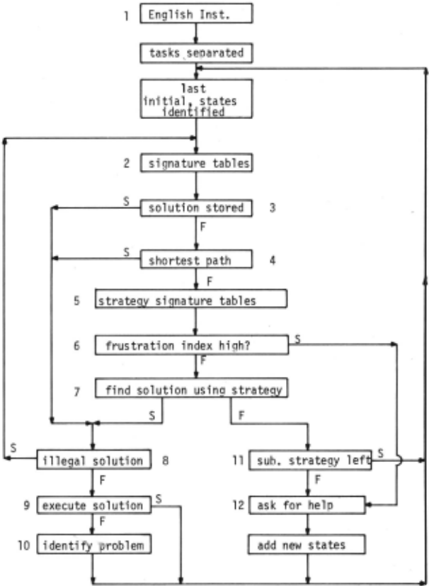
Finally, the third and one of the most difficult portions of the robot is its software. The executive control programs are primarily oriented toward simple problem solving and adaptation to variations in the environment. Figure. 6 shows a flowchart of Jason's executive program. Technique>such as signature tables [11], shortest paths [12], strategy learning [13], and problem solving methods [14], are under development. Once the mechanical and electronical sub-systems of the robot have been implemented, the bulk of the research pursued in this project. will be on the software. A future paper will report on orogress in this area as soon as some empirical results are obtained.
IV. Safety Precautions
Once a robot with the above capabilities and func tions is operational, a major problem remaining is how to achieve adequate safeguards to ensure the safety both of the robot itself and the humans that may be in the vicinity. A robot that is simultaneously mobile, fast, powerful, and unpredictable can be hiahly danger ous if well-conceived nrecautions are not scrupulously observed. Thus, various hard~1are and software safety devices, operational precautions, and other ground rules must be formulated and implemented before any robot should be releas€d into the human world to carry out even tlie simplest task. Jason is to have three types of safety devices and controls: (i) those built into the robot's hardware, (ii) those built into the sofb1are, and (iii) those observed by the exoerimenter (s) during robot operation. All of these are being studied and will be implemented before Jason is permit ted to operate in a human . environment.
V. Summary and Conclusions
The Berkeley Robot Project is concerned with a relatively unexplored area of robotics -- that of designing, implementinq, and of operatin~ an economi cally viable and durable robot, capable of performing useful tasks in a human world. As mentioned in this paper, there remain many Problems to be explored further, such as:safety precautions, planning vs. exe cution, sensory integration, etc. Such research is clearly required if a robot is to be released into the real-world without an inordinate number of restrictions and constant surveillance. The Berkeley Project is in the midst of desian and construction. Some devices have been completed and checked out. Others, such as the arms, are still in the desiqn stage. It is planned that a fully integrated robot vehicle with elementary control software will be operational in the near future. Once operational, Jason will primarily be used as a test bed for the development of future, real-world robots with considerably greater sophistication and intelligence.
Acknowledqments
The authors wish to thank various graduate students and members of the faculty of the Department of Electrical Enqineerinq and Computer Sciences of the University of California at Berkeley, especially including Professors C.V. Ramamoorthy, Douqlas Maurer, and Arthur Hopkin, and E.E.C.S. students Al Robb, David Ott and Ken Holt. Messrs. Leonard Baldwin and Wilfried Zeilinger of the Departmental Machine Shop were responsible for much of the construction. Miss Barbara Kerekes did many of the final drawings. Also, students in EECS 290G contributed much to the project.
In addition, we appreciate the help of various members of the staff of the Artificial Intelligence Center and the Augmentation Research Center at Stanford Research Institute, especially Dr. William Rupert, Mr. Jerry Gleason, and Mr. Kirk Kelley. We would like to acknowledge the computer time, equipment, and considerable encouragement provided by the Lawrence Hall of Science of the University of California at Berkeley. Finally, we would like to thank the Veteran's administration for the loan of an ultrasonic "torch", and Scientific Technology, Inc. for the loan of the LED proximity detectors.
@inproceedings{ijcai1973p42,
  title     = {Design of a Low Cost, General Purpose Robot},
  author    = {Smith, Michael H. and Coles, L. Stephen},
  booktitle = {Proceedings of the Third International Joint Conference on
               Artificial Intelligence, {IJCAI-73}},
  publisher = {International Joint Conferences on Artificial Intelligence},
  editor    = {Nils J. Nilsson},
  pages     = {324--335},
  year      = {1973},
  month     = {8},
  note      = {Robot I mplementations},
  url       = {https://ijcai.org/proceedings/1973/42},
}
TY - CPAPER TI - Design of a Low Cost, General Purpose Robot AU - Smith, Michael H. AU - Coles, L. Stephen T2 - Proceedings of the Third International Joint Conference on Artificial Intelligence, IJCAI-73 PB - International Joint Conferences on Artificial Intelligence PY - 1973 SP - 324 EP - 335 UR - https://ijcai.org/proceedings/1973/42 ER -Copied
Machine-readable versions of this paper, for tools and AI agents:





