
Design of a Computer Controlled Manipulator for Robot Research
Proceedings of the Third International Joint Conference on Artificial Intelligence. Robot I mplementations. Pages 291-296.
© 1973 International Joint Conferences on Artificial Intelligence
Abstract
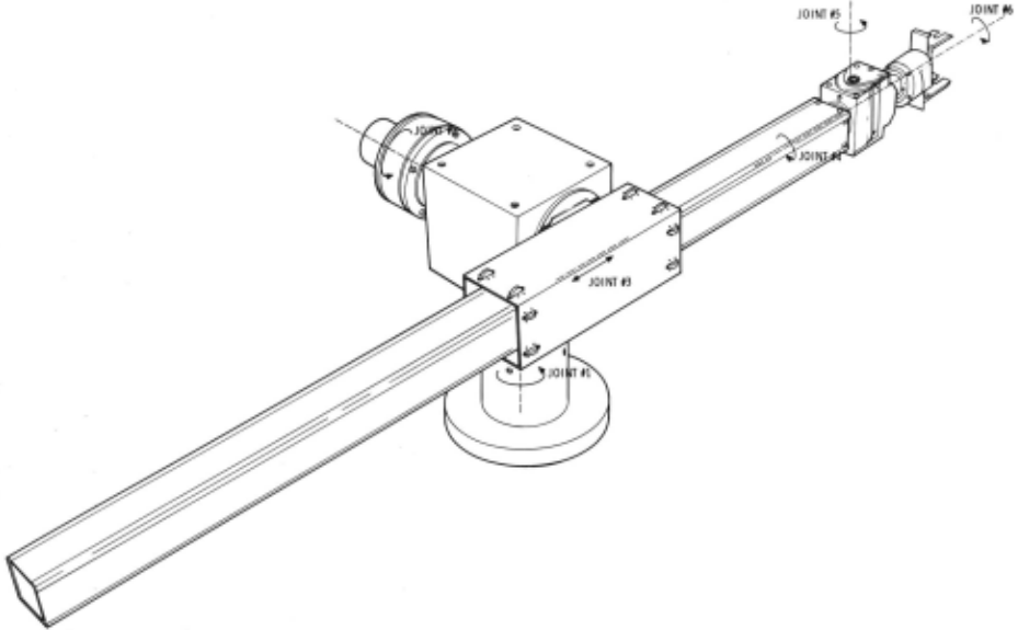
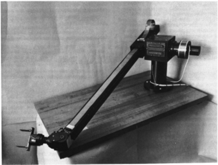
The purpose of this paper is to describe the Jet Propulsion L aboratory Robot Research Project's manipulator, including the rationale behind the design and the detailed design trade - offs that were made. It is intended to assist ot her wor kers in Artificial Intelligence ( AI) w h o need to develop manipulators for their own use. A discussion is presented of the constra int s and requ irements imposed on th e manipulator which led to the basic design, which was developed by Stanford Uni vers it y's Artificial Intelli gence Project. Furth er, detai l is pres en ted on the implementation of the basic conf igur ation. The end result is a man i pulator which reproduces th e flexibility and speed of a human arm. The manipulator is designed t o be integrated with a vehicle and is complete ly computer controlled. Human comman ds are inje c ted only a t the gross instruction level, with a digital computer generating th e contro l leve l commands. The JPL requirements are for the manipulator t o pick up irregular objects from the laboratory working area , or surface, and move them t o an arbitrary position e ither on or o ff the veh icl e, while avoiding any obstacles. The manipulator ( Fig. l) has 6 degrees of freedom whic h allow the grasping device (h and ) to be placed in any arbitrary position with great flexibility. Th e joints from the base to the hand co nsist o f two rotary joints, one linear joint a nd three rotary joints (2R, lL, 3R using the nomenclature of Ref. 1). This allows the hum an waist, shoulder, arm and wrist motions to be reproduced. Manipulator reach is a maximum of 52" and an object of abou t 5 pounds may be lifted. The manipulator may reach an ob je ct in any part o f a sphere that is not occup ied (i. e. , by the vehicle, floor, etc.). System resp onse allows a maximum motion to be accomplished in about 5 seconds. P ower is supplied by 6 permanent magnet DC torque motors geared directly to each link. For th e first four inner rotary joints, harm on i c drive gearing is used, w it h rack and pini o n drive for th e linear joint. For the o ut er rotary joint, spur gearing is used. DC power is provided through analog DC amplifiers t o minimize electrical n oise. Analog position and rat e fe edback inf orma ti on is provided. B rakes are used in each joint to pr ovide holding torque.
Full text extracted automatically from the PDF; figures, tables and equations may differ. The PDF is the version of record.
Introduction
The Jet Pr opulsion L aboratory is conduc ting a robot research program wi th the end goal of allowing planetary exploration to be conducted with minimal human supervision. A mission using a mobile r ob ot expl o ring the surface of Mars has been selected as a focal point for equipment development and experi mentation. It is felt that a system of this type would be typical of those that might be used for space ex ploration; telecommunicati on times prevent a tele operator system fr om being used efficient ly, but man still needs to exert supervision over the r obot's acti vity.
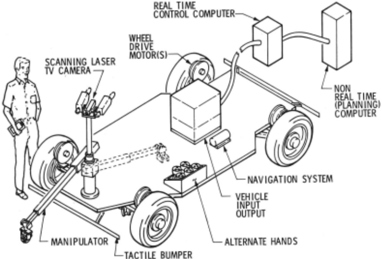
The breadboard r obot being assembled (Fig. 2) will cons ist o f a non -r eal -time computer, a real time control computer and a vehicle with a manip ulator and imaging system. The intent o f the bread board is to pr ovide an actual demonstration of the robotic capability being developed .
The initial tasks selected for the robot are simple and depend on man setting the goal. These tasks are intended to demonstrate that a minimal capability has been achieved. Primarily they include the vehicle moving from one point to another, avoiding obstacles; and for the manipulator to grasp an objec t on the ground, h o ld it up for inspection and place it on the vehicle or elsewhere. This sequence is t o be car ried out automatically, wi th the human operator intervening only in the event of problems.
An additional constraint on the JPL program was designed to make maximum use of existing sys tems . The benefits of this are obvi ous: both devel opment time is saved and previous experien ce of others can be applied.
Thus, an investigation was made t o determine if a suitable m a nipulator exis t ed. The manipulator requirements we re: a good interface with a digital computer, the ability t o be integrated with a vehicle and to wo rk fr om the vehicle, low power consumption and light we i ght. In addition, it s h ou ld be able to work with position information based on a coordinate system which could be derived from laser or TV data.
The Stanford "Hand -Eye" project provided a manipulator design which could be modified to fulfill JPL' s r equirements (Ref. 2). This manipulator is the r esult of extensive comput er - driven arm exper ience and is an exis ting, proven des i gn. It has demonstrated the flexibility to do stacking a nd assem bly tasks.
JPL' s requirements dictated that the manip ulator's capability be changed in th e areas of working volume, servo contr o l response and cont r ol software. However , since the basic JPL requirements were met, r edes ign was kept to a minimum.
System Design
Two factors which are basic to any manipulator design are the kinematic configuration and the drive power for each link. The JPL manipula tor must be able to work in a non-repetitive fashion in the angular volume defined by approximately 75o/o of a sphere. Kinematically, this requires that the hand have a full six degrees of freedom, leading to at least six single degree - of-freedom joints. In order to reduce me chanical complexity joint redundancy was not included.
Ref. l describes a configuration which gives a simple solution for the joint positions versus the hand position. This solution is for a six - degree-of freedom manipulator which has three revolute joints whose ax.es intersect at a point. Since a simple analytic solution for the desired manipulator motion minimizes the required computer calculations and allows a smooth trajectory to be developed for each link motion, this configuration was implemented.
The next step was to select the type and arrange ment of the remaining joint variables. The primary choices were between an anthropomorphic type ma nipulator, with all rotary joints, or a "mechanical" type manipulator which replaces the human elbow with a linear joint. Both configurations have a verti cal and horizontal degree of freedom at the base. The difference in the two designs is in the method by which reach is provided. The humanoid manipulator provides a rotary joint in the center of the "arm" (an "elbow") while the mechanical manipulator pro vides a sliding joint at the shoulder, giving a one piece arm. The humanoid version does not have a boom protruding from the back for close -in work and offers more flexibility in operation. The linear joint allows a more rigid assembly and provides a lighter arm since the linear mechanism requires only one high torque joint, which is housed in the shoulder and does not contribute to gravity torques . The rotary elbow joint on the other hand requires a high torque joint which is capable of producing at least two - thirds of the torque that the shoulder joint develops. The weight of this joint (motor, gears, housing, bearings ) then increases the load on the shoulder joint.
Given the basic configuration and the required dimensions (Ref. 3), the type and size of the link drive mechanism may now be chosen. There are two basic choices: hydraulic power or electric motor drive. Hydraulic power has the advantage of placing the main power source, the pump, apart from the manipulator. This allows the link actuators to have high power levels in a small volume. However, electric motors directly coupled to the link provide a simple interface with the computer . The size and loading of the JPL manipulator does not require high power, allowing the use of electric motors.
Several types of torque motors are available: AC, DC and stepper motors with DC torque motors being selected. AC motors have enjoyed wide popu larity in the past, but in general they are being superseded by DC motors . This is due to the fact that AC motors require an AC inverter, cause more noise than DC motors and have a more complex computer inte·rface. Stepping motors are an obvious choice for a digitally controlled positioning device, since they provide discrete steps and also provide holding torque when unpowered, and are widely used in spacecraft actuators. However, stepper motors would have required more room to install, resulting in a larger boom, as well as outer links. Therefore, DC torque motors were retained.
Permanent magnetic DC torque motors were chosen for their efficienc y and linearity. Torque is a direct linear function of armature current. Addi tionally, because of self - generated feedback voltage, the speed - torque curve for a given voltage is linear , with maximum torque occurring at stall. This com bination of linearity and maximum torque at stall fit the requirements of the manipulator perfectly .
The motors are coupled to the rotary links through gearing. To make the gearing as compact, light and accurate as possible, Harmonic Drive was selected for the rotary joints. This choice allows high gear ratios (- 100: l) in an in-line package that fits conveniently within each link, even though spur gears provide higher efficiency. Spur gears are used in the sixth joint, since there are only small torque loads. Direct rack and pinion drive is used for the linear (third) joint.
Electro-mechanical brakes are used in each link to allow the arm to remain stationary in any position without using motor power. These are normally off brakes and require power for braking . The more desirable normally on brakes which require power for removal of braking torque are too bulky for use in the manipulator and have a much lower holding (static) torque for a comparable size.
Thought was given to the use of motion limit switches to limit the manipulator's motion and pre vent damage . This proved infeasible due to the fact that the danger zones were configuration dependent. A joint limit that could harm the manipulator in one position would be quite acceptable in another position. The only limiting device that is included is logic t o prevent a computer failure from overdriving the manipulator. The computer must reset a bit in the interface logic every sample period or power is re moved from the motors and brakes are applied. This protects against both software and computer hardware failure.
Sensory or feedback information is obtained from each joint separately. Ref. 4 presents a linear analysis of several servo loops which may be used to control each joint variable. In each case stable operation is assured when both position and rate in formation is used . Position information is provided by analog potentiometers located at each link. Expe rience has shown that rate information is best obtained directly. Computer differentiation of position data creates noisy rate information, especially at low rates. Therefore, each link has a tachometer mea suring rate directly.
Since the total hand position error is the sum of the individual link position errors, link errors must be minimized as much as possible. To reduce the effects of gearing backlash, the rotary joint potentiometers are mounted on the output side of the gearing . Thus, the position readout for each link is absolute and gearing backlash only affects the maxi mum servo loop gain. For the linear joint, the potentiometer is connected to the motor, but the back lash in the rack and pinion drive can be held to - 0. 005", which is acceptable.
The position feedback information should be good enough to allow the desired accuracy to be obtained. To provide an overall positioning accuracy of 0. 10 inch, at maximum reach, each joint must have an absolute position accuracy of 0. 05o/o or an equivalent 12 - bit aq:uracy. The ideal choice here would be a 12-bit absolute value digital encoder.
However, these are bulky (and expensive) units which need one wire for each bit. The next choice is an incremental digital encoder with an up/ down counter. These can be purchased with the stationary readout station separate from the optical disc, in standard servo sizes. Unfortunately, production readout devices are too bulky for the outer joints (whkh precluded their use). Analog potentiometers were selected with the option of later changing to digital encoders, if smaller ones become available .
At the present time, flat face analog potenti ometers are used in the four critical rotary joints with multi-turn potentiometers on the other two joints .
Structural design concentrated on providing maximum stiffness (minimum deflection) consistent with light weight. For the first two links, weight is secondary to stiffness since the weight in these links does not contribute to any manipulator gravity loads. The third (linear) link weight lifting capacity is directly limited by the boom and outer joint weight. These items must then be made as light as possible. In addition, link alignment is maintained by use of precision (class 3) ball bearings. A simple interface is provided between the hand and the sixth link. This allows simple interchange of hands as desired.
Detail Design
The main manipulator d imensions (height of the base pedestal and boom length) were dictated by the established vehicle dimensions and desired set of reachable points on the ground. Primary considera tions were to make the reach long enough to reach the ground, yet keep the boom short enough to avoid obstacles on the vehicle (wheels, drive motors, other subsystems, etc.). Once the height of the shoulder and the maximum reach of the boom were set and the components selected, packaging and installation requirements determined the link dimen sions.
The freedom of each joint with the exception of the linear joint and joint 5 is theoretically infinite. Practically, the actual limits are imposed by the electrical wiring since slip rings are not used . Therefore, each free joint is limited to ±170°. Joint 5 limits are ±90° and the boom travel is 38 inches . The total maximum reach is 52 inches. The maxi mum finger mechanism opening is 4 - 1/2 inches.
Printed circuit motors were selected for the first two link drives, unhoused motors for the next three links and small housed motors for the last link and hand. All were 28 Vdc motors .
For the first two joints prime considerations are high torque and smooth operation (low "cogging" or variance of torque with angular position). The motors selected offer high torque capability at a reasonable size. Since the manipulator duty cycle is low ( 1-10%) average power is not important but peak power is. In addition, most link trajectories used with the manipulator require acceleration to be a linear function of time with zero torque at the start and finish of each trajectory. Therefore, stall torque (torque at zero speed) is only needed for gravity torques. This last item is important since stall current is 29 amps for the link 1 motor and 32 amps for link 2.
The motor for link 3 (boom) is unhoused and mounted in the drive barrel for the boom elevation link. This is a high torque motor directly coupled to the load . It is a conventional motor, as compared to the motors which drive the next two links. These are pancake-type motors that are wound in half the nor mal length. The unhoused motors require special housings and support shafts but they offer greater flexibility in packaging with the gear drive, tachom eters and brakes.
The small C series Harmonic Drive units were used. The hand selected (optimized) option for the component sets was specified in order to reduce lost motion by a factor of three to 3 to 5 arc minutes. Only part of this is backlash, the remainder being initial wind - up. The nominal maximum output rating of the Harmonic Drive units is exceeded, but with the low duty cycle an overload of up to 300% is per missible, with nitrided units capable of even greater overloads . As in all gearint:;. it is very important to provide enough shaft support to maintain concen tricity of the gearing set. In addition, the design must permit assembly and checkout of the Harmonic Drive unit prior to installation.
Gear ratios were chosen to optimize the driving I driven inertia ratio. The driving inertia consists of the inertia on the input shaft: the motor armature, tachometer armature, etc. The driven inertia is the load inertia or the link inertia. The inertia reflected from the input shaft to the output shaft is increased by n 2 where n is the gear ratio. When the reflected input inertia equals the output inertia, maximum power is transmitted. As an example, the first link drive motor has an armature inertia of 0. 0055 oz. in. /sec2, with a gear ratio of 100 to l, which for .maximum power transmission indicates that the load inertia should be 55 oz. in./ sec 2 .
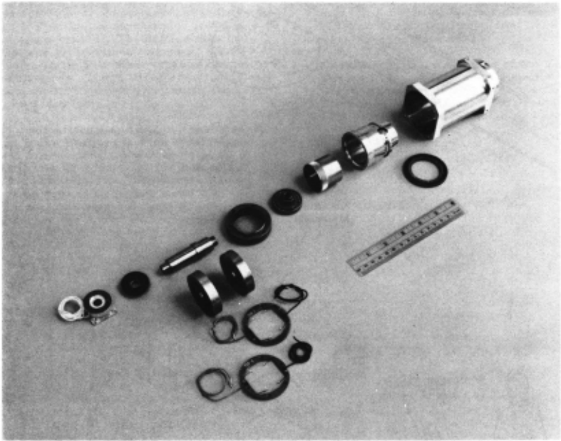
The brakes and tachometers are mounted on the same shaft as the motor for the first five links. Fig. 3 shows an assembly view of link 4. The brake is at the left, the tachometer and motor next, then the Harmonic Drive, output shaft, potentiometer and link drive housing. The tachometer!> selected for these links are physically identical to the motors driving the fourth and fifth links (shown in Fig. 4). This similarity allows part interchangeability (brushes and field magnets) and simplifies the instal lation problem. The brakes selected are capable of holding the links stationary against the largest expec ted gravity loads. In links 3 through 6 and the hand, the brake torque exceeds the motor torques. In the base the only gravity torque is on joint 2, where the brake is capable of holding a 5-pound object at maxi mum extension. Zero backlash units are used. All brakes, tachometers and motors are assembled so that they may be disassembled. There are no press fits or plastic cements and the magnetic keepers can be reinstalled on the motors and tachometers prior to removing the armatures . Since the purchased parts are commerc i al items, dimensions may vary from the manufacturers specification sheet. The least costly way of allowing for this is to provide the purchased parts to the machine shop at the time of fabrication. Of course, this would not be practical for a mass produced manipulator and dimension control drawing would be used. A zero-buildup green anodize was used to provide better spectral response to the TV cameras.
The nonstandard potentiometers were manufac tured at JPL. Sheets of conductive plastic were bonded to a fiberglass backing and the backing and resistive element machined to size. A single pick-off is used, limiting the measurement angle to 355°. The other potentiometers are standard multi-turn items. The boom potentiometer is a 15 turn, 0. 0 l% linearity device, while the hand unit is a 5 turn, 0 . 05% device.
Since the sixth link has only inertia loads and the hand task is only to grasp an object, the prime consideration in this design was size, both of com ponents and their packaging. The smallest compo nents available were chosen, and rather than mount them co-linearly, the components were clustered around a central axis . This gives a short length (and less gravity torques) at the expense of increased diameter. This was also a reason for eliminating the use of slip rings .
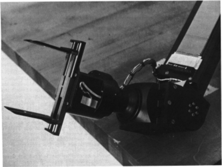
The hand shown in Fig. 4 is a simple parallel jaw device. It is driven by a motor identical to the one used in link 6. Position feedback and a brake for holding loads are provided. The hand is attached to the sixth link at one plane with six screws, allow ing easy interchangeability with other types of hands or other terminal devices. E x tra wires are provided for additional hand sensors (proximity, limit switches , etc . ) which will be added later .
Wiring the manipulator was a major considera tion during design and a complex task on assembly . The main criteria is to separate power and signal leads, shield all wires, provide loops for link rota tion, minimize the resistive drop, and avoid ground loops . The problem area is in the boom and the outer links. Two separate shielded flat conductor cables are used across the linear joint. One contains power and returns for the moto rs and brakes, while the other is devoted to instrumentation. Provision is made for routing wires through the center of the link drive motors as well as around the link where possible.
In a further effort to reduce noise, analog drive circuitry was selected, as opposed to pulse width modulated ( PWM) drive. Some efficiency is lost, but the analog drive does not produce the noise on the instrument lines that PWM does. Since high gain amplifiers are used they may be configured to give either a linear voltage gain or a linear voltage to current conversion. The latter gives more pre cise control and eliminates the computation of back EMF from the servo loop. However, a linear vol tage gain may be configured in a bridge circuit, eliminating the need for both positive and negative voltage supplies.
Conclusions
An AI manipulator has been designed and is shown in Fig . 5. This manipulator is representa tive of the class of manipulators which have fast response, high torque output and high accuracy. In addition, it is suitable for use with other "effector" subsystems, such as a vehicle.
The manipulator design provides a great deal of flexibility in the way it can be controlled, in its applications and allowances for further development. There are a variety of control modes that can be accommodated: complete computer control or par tial analog servo drive; current drive or voltage drive. It may be used in a system that is primitive at the start, with only crude sensory data, and yet the design is sophisticated enough to perform com plex tasks. Further development is needed in the area of the hand and providing total closed loop control. Closed loop control is be ing studied at the moment.
Presently, the manipulator is being integrated with the drive software and its operation demonstra ted in a stand-alone mode. Integration with the vehicle is planned in the near future.
Refer ences
- Pieper, Donald L., "Kinema tics of Manipula tors Under Computer Control," Stanford University , October 24, 1968.
- Schienman, Victor D., "Design of a Computer Controlled Manipulato r," Stanford University, June 1969.
- Bejczy, A., "Work Space Analysis for Vehicles Mounted Arm," Jet Propulsion Laboratory, G&C TM 165, June 1972.
- Markiewicz, B., "Analysis of the Computed Torque Drive Method and Comparison with Conventional Position Servo for a Computer Controlled Manipulator, " J et Pr opuls ion Laboratory, TM 33 - 601, December 1972.
@inproceedings{ijcai1973p38,
  title     = {Design of a Computer Controlled Manipulator for Robot Research},
  author    = {Dobrotin, Boris M. and Scheinman, Victor},
  booktitle = {Proceedings of the Third International Joint Conference on
               Artificial Intelligence, {IJCAI-73}},
  publisher = {International Joint Conferences on Artificial Intelligence},
  editor    = {Nils J. Nilsson},
  pages     = {291--296},
  year      = {1973},
  month     = {8},
  note      = {Robot I mplementations},
  url       = {https://ijcai.org/proceedings/1973/38},
}
TY - CPAPER TI - Design of a Computer Controlled Manipulator for Robot Research AU - Dobrotin, Boris M. AU - Scheinman, Victor T2 - Proceedings of the Third International Joint Conference on Artificial Intelligence, IJCAI-73 PB - International Joint Conferences on Artificial Intelligence PY - 1973 SP - 291 EP - 296 UR - https://ijcai.org/proceedings/1973/38 ER -Copied
Machine-readable versions of this paper, for tools and AI agents:





