
The Use of Vision and Manipulation to Solve the "Instant Insanity" Puzzle
Proceedings of the Second International Joint Conference on Artificial Intelligence. Pages 359-363.
© 1971 International Joint Conferences on Artificial Intelligence
Abstract
This paper describes a system which solves the puzzle "Instant Insanity". The puzzle cons i sts of four multicolored cubes. The solution involves arranging the cubes in a tower so that no side of the tower reveals more than one face of a given color. Our system, which runs as eight (multitask) jobs under the PDP-10 timesharing system, uses a TV camera to locate four objects and, having verified that they are cubes, to f1nd the color of each face. A mechanical arm turns the cubes over to expose all faces to the TV. Having found the solution, the arm then stacks the cubes into a tower to demonstrate it.
- K. K. Pingle, J. A. Singer, & W. M. Wichman, "Computer Control of a Mechanical Arm Using Visual Input", Proceedings IFIP Congress '68, Booklet H, pp. 140-146, North Holland, 1968.
- J, McCarthy, L. D. Earnest, D. R. Reddy and P. J. Vicens, "A Computer with Hands, Eyes, & Ears", Proceedings Fall Joint Computer Conference, 1968, Vol. 33, Thompson Book Company, pp. 329-338.
- R. F. Sproull, D. Swinehart, "SAIL", Stanford Artificial Intelligence Project Operating Note 57.1, 1970.
- J. A. Feldman, P. D. Rovner, "An Algol-Based Associative Language", CoiiiDunications ACM, August, 1969, pp. 439-449.
- J. A. Feldman, R. Sproull, "System Support for the Stanford Hand-Eye System", Proceedings of the 2nd International Joint Conference on Artificial Intelligence, London, 1971. IJCAI
- I. Sobel, "Camera Models and Machine Perception", Session No. 8 Robots and Integrated Systems Stanford Artificial Intelligence Project Memo, AIM-122, Stanford University, May, 1970.
- K. Pingle, J. M. Tenenbaum, "An Accomodating Edge Follower", Proceedings of the 2nd International Joint Conference on Artificial Intelligence, London, 1971 .
- G. Falk, "Recognition of Occluded Objects Using a Computer", Proceedings of the 2nd International Joint Conference on Artificial Intelligence, London, 1971.
- R. Paul, "Computer Controlled Manipulation at Stanford", Proceedings of the 2nd International Joint Conference on Artificial Intelligence, London, 1971.
- L. G. Roberts, "Machine Perception of 3- Dimensional Solids", J. Tippet et al (Eds) Optical and Electro-Optical Information Processing MIT Press, Cambridge, Mass. pp. 159-197, 1965 . .
- J. M. Tenenbaum, A. C. Kay et al, "A Laboratory for Hand-Eye Research", Pro- ceedings of IFIP, 1971 Congress, Ljubljana.
References were extracted automatically from the PDF and may contain errors.
Full text extracted automatically from the PDF; figures, tables and equations may differ. The PDF is the version of record.
1. INTRODUCTION
For several years the Stanford Artificial Intelligence Proj ect has been doing research in visual perception by a computer and computer control of mechanical manipulators in an attempt to achieve direct computer interaction with the environment. Early programs were written to demonstrate that a particular task could be accomplished and could not perform other tasks, even if quite similar , without being extensively rewritten . Generality unnecessary for the task at hand was sacrificed to keep the programs as
*Currently on leave to The University of Jerusalem **Now at Computer Science Jepartment, Rutgers University
***Is now at NIH Bethesda, Maryland ****With Lockheed Palo Alto Research Labs small as possible so they would fit the core limitations of our compnter. The main result of this resea~ch waa the development of programs which could find and stack cubes, either sorting them by size (1), or ordering them by voice command (2).
IIThis research was supported b~· the Advanced re search Projects Agency of the Department of De fense under Contract No. SD-183. The views and conclusions contained in this document are those of the authors and should not be interpreted as necessarily representing the official policies either expressed or implied, of the Advanced ' Research Projects Agency of the U.S. Government.
Recently we have been doing more fundamental research involving better edge detectors, color and texture recognition, classification of objects, coping with partially described objects, and the design and use of manipulators . Many programs have been developed with varyin~ degrees of generality. A monitor has been designed which allows those programs necessary to perform a particular task to run as separate jobs, with the flow of control between them established by a separate control program which is the only part of the system tailored to the task. This not only reduces the problem of specialized interfaces between the programs needed for the task, but gets around our core limitations,
Some of the programs are used to their full capabilities while only part of the generality available in others is required for a specific task. A new task requires only a new control program, which will select those programs it needs.
This paper describes the first specific task we have programmed using this new system, which was designed to enable us to debug the various parts of the system. It attempts to solve the puzzle "Instant Insanity". The puzzle consists of four cubes, each with faces variously selected from four colors: white, blue, red, and green. To solve the puzzle, the blocks must be stacked so that each of the four sides of the resulting tower reveals only one face of each color. Determining the orientation of the cubes in the tower is normally quite difficult for humans. For the computer this is relativelY, easy; most of its time and effort is spent in locating and identifying objects, determining the colors of the faces, and, having found the final orientation, deciding what arm motions are required to physically produce the tower.
2 , HARWARE
The visual input is done using a commercial TV camera. The camera has a four lens turret, a four position color wheel in front of the vidicon, a pan-tilt head, focus, and target voltage all under program control. The com puter can input, under program control, four bit intensities from any rectangular area of the field of view up to 333 x 256 points. The arm currently in use was designed and built at Rancho Los Amigos Hospital near Los Angeles as a device to be fastened to a paralyzed human arm. It is powered by small electric rr.qtors mounted on it. Each of the six joints has a potentiometer mounted on it to provide position feedback. The hand is a two-finger parallel grip device about the size of a human hand. The arm is controlled by DC pulses, the width of which is varied by the program to con trol the speed of the arm. The TV and arm are connected, through analog to digital converters, to a Digital Equipment PDP-6 and a PDP-10 computer linked together and sharing 128K of core.
3· SOFTWARE (11)
The system runs under Stanford's PDP-10 timesharing system, which has been modified to enable our system to function in a time sharing environment. Most of it is written in SAIL, an ALGOL like language developed by our project (3) which contains the LEAP associa tive processing language (4). The entire system is 200-250K in size without debugging routines.
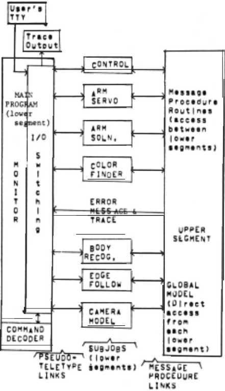
To enable various sections to run asychron ously, and to fit it into core, the system runs as eight separate programs. [See Figure 1), The PDP-10 has two relocation registers, allowing a program to be in two disjoint segments in core. In our system, one of these segments, known as the upper segment, (5 ) is common to all the programs and contains reentrant subroutines common to all programs. In addition, it con tains data which provides a complete global model of the world as it is known to the system at any given time. This model is gen erated by the lower segment programs and can be interrogated by them. Much of the model is in the form of LEAP associations.
The basic elements of LEAP are items, symbolic literals similar to LEAP atoms. They can be put in sets or into associative relations called triples. A typical triple is written "COLOR ® CUBE=RED" and is read "color of cube is red", The items in the triple can be de clared at compile time or created as they are needed, An element of a triple can also be another triple as shown below. Any element of a triple can be retrieved by reference to the other two elements. Each item can have assoc iated with it a datum, which may be a number, set, or array,
Many triples are created by the various programs in this system, Some are for the use of only that program and are stored in a local area in the program. Other triples are stored in the global model area of the upper segment. Below are three of the major triples in the global model as examples of the represen tation of objects in our system. The capitalized items are declared; the others are created at run time.
INSTANC~CUBE=object where the datum of object is a 4 x 4 array specifying its position
ED�E~object:a where the datum of a is an array containing the edge coordinates for dis playing the object
COLOR®[FAC~object:F 1 ):Cj where Fi is one of the six declared face items and C. is one J of the four declared color items
The triples are accessed mainly by a FOREACH statement, which is similar to the ALGOL FOR statement. A typical one in our control program is
FOREACH HUE, FAC I COLO~[FAC~OBJ:FAC):HUE DO BEGIN COMMENT OBJ is an itemvar, a variable whose value is an item, which contains one of the object items, The body of the statement is executed once for each triple found which matches the "such that" part of the FOREACH specification with itemvars HUE and FAC bound to the elements of each triple in turn;
In order that the programs may easily trans fer control from one to another, we have imple mented a construct which we call message pro cedures. When a program executes a message pro cedure it specifies, in addition to the name of the procedure and its arguments, the symbolic name of the program containing the procedure. The name and arguments are copied into the upper segment and , when the program containing the procedure is ready, it is activated from the upper segment. The calling program may continue as soon as the upper segment has the information on the message procedure, or it can be put to sleep by the timesharing system until the other program finishes execution of the pr ocedure . Programs waiting for message pro cedures they contain to be requested can also be
put to sleep.
Below is a brief description of each of the lower segment programs, except for the control program, which will be discussed in detail later. A reference to a more complete description is given for most programs.
3a. The Hand-EYE Monitor (5)
The monitor is the only program which com municates directly with the operator. It creates 'pseudo-teletypes' (PTYs ) and logs in jobs through them. Then, all characters sent to a PTY by the monitor go to the teletype input buffer of the j ob attached to the PTY and any teletype output from a job is available to the moni tor. I t also contains facilities for directing teletype input to the proper job, outputting teletype output from the jobs to the operator wi th the job identified, tracing the teletype I / O and message procedure calls for debugging, and setting up and controlling the other jobs. Jobs may activate a message procedure in the monitor
to send commands to it.
3b. The TV Camera Model (6)
This is a small program which reads in a calibration file from our disk and uses it, along with the readings of the potentiometers attached to the camera 's pan-tilt head, to determine the transform which takes points in the camera's coordinate system into the arm's coordinate sys tem , based on a grid on the table on which both devices are mounted. If the camera is moved, this program can be activated to provide a new trans form. The current transform is stored in the global model.
3c. The Edge Follower (7 )
The edge follower scans the TV's field of view, using a coarse raster, looking for edges. When one is found, the program traces around it to f i nd the outline of the object, If the bright ness of the areas scanned varies too much to keep the i ntensities ins i de the range of the hardware, the target voltage is changed to adjust the camera's sensitivity. Various heuristics are used to trace faint or noisy edges. After an object's outline has been traced, strai ght lines are fit to it, a list of the corner coordinates i s put in the global model and the current camera transform associated with the list. An internal model of the field of view is maintained by the edge follower to tell it what has al ready been seen so it will not trace objects already found, The program can be directed to delete an object from its model and retrace it if the original trace was not good enough. The edge follower is able to trace objects in more complicated scenes than are presented to it by this system, which is restricted by the object recognition program. Objects with curved edges can be traced also but the current curve fitter can only fit straight lines.
3d. The Simple Body Recognizer (8)
This program gets the corner coordinates of the objects in the global model and applies various tests to obtain a prediction as to what the object may be. It then attempts to match the object's outline against the outlines of prototype objects which it has stored in the global model , using its prediction to select the prototypes to be matched, The current proto t ypes include rectangles, rhomboids, wedges and L·beams, The program can recogni ze objects only if each outline given it is of only one ob j ect [ Figure 2-a ] and not of several objects , some of them partially occluded. [ Fi gure 2-b ) Also, it cannot handle head-on, or degenerate views. [ Figure 2-c ) If the program is able to recogni ze the object, it generates the 4 x 4 matrix which translates the prototype of the object , located at a standard pos i tion, into the object found. This enables us to represent the objects with a minimum of information as the topological information is stored only once for each class of objects. ·
In the global model this matrix is asso ciated with the object. In addition , the coor dinates of each corner are as sociated with the object for display purposes and the normal vector to each face is associated with that face
and object to give the orientation .
While the body recognizer is able to re cognize many classes of objects (in addition to those listed above, new prototypes can be added with relative ease), this system uses the program only to determine whether or not an object is a cube.
3e . The Color Finder
The camera has a color wheel between the vidicon and the lens with a red , green, blue, and neutral filter. The color recognizer reads the intensity in an area at t he center of each face through each of the colored filters and
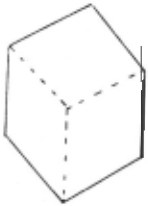
- a, Simple outl i ne
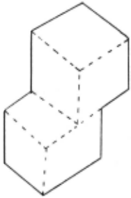
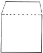
c. Degenerate outline
normalizes the resulting vector for each face. It the ~ finds the co lor of the face by determining which &rea of the color space the vector is in.
3f. The Arm Solution (9)
This program is given two matricies. One gives the current position and orientation of a cube and the other gives its desired position and orientation.
The wrist joint is oriented to grasp the cube by a pair of opposite faces if possible; otherwise, opposite corners will be used. Having found the position of the wrist, possible positions of the other joints are calculated and one se lected which satisfied the constraints on the arm's motion. The result of this program is a series of E-tuples giving the potentiometer readings the arm will have in desired positions. The first is a position directly over the cube. To make sure the arm moves straight down, so as to not knock over any nearby cubes, it is moved through two positions on the way down to grasp the cube. The sequence is reversed to lift the cube, which is then moved into position above the final position. Another pair of positions is used first to lower the cubes and then to raise the arm , which either waits for the next sequence of moves, if any are ready, ·or retires to a standard position out of view of the TV.
Fi gure 2 Types of Outlines
3g. The Arm Driver
The potentiometer readings generated by the arm solution program are obtained and the arm joints are servoed to each successive group of six readings. Since the arm currently does not use visual feedback, after the cube has been moved and released the fingers are closep again to determine if the cube stayed in position. If the program ever detects that its fingers are empty when they are supposed to contain something, the calling program is notified, The servo loop is executed by the timesharing system in a special mode which guarantees it ser.vice at intervals of 1/ 60 second in order that the arm will run smoothly and not overshoot its target. This mode prevents the job from being swapped out of core when running. Therefore, this is a separate very small job rather than a part of the arm solution program so as not to lock other users out 'of core.
4 . THE CONTROL PROGRAM [Figure 3]
The heart of the system is the eighth job, the control program. It sequences the various tasks, attempts error recover, generates displays, and has Provision for running parts of the sys tem by themselves for debugging.
When the program is started, all the other jobs except the camera model are assumed to be set up and waiting for instructions. Their status is checked during the run to insure that they are ready when they are to be acti vated. The program sets up the camera model program to get the transform and then, since the camera currently is not moved during the run, it is killed.
The first task is to find four cube s . The edge follower is as ked to find an outline. Curve fitting is performed and the result tested for a degenerate vie~ . If it is degenerate, t he arm rotates it 45° and it is traced again. Also, if a complete curve was not found, or if the body recogni zer cannot verify that the ob ject is a cube, it is rejected and the edge fol lower traces it again. Since each trace begins just beyond where the last edge was found, the object will be found at a different point on the outline each time, which gives it a better chance of eventually tracing correctly even an object with poor contrast. Since noise in the input usually resembles very small objects, the scan will not encounter t he same patch of noise on later scans. If necessary the entire field of view will be scanned twice to find all four cubes before admitting failure.
The color recognizer is called to obtain the colors of the faces visible to the camera . Then the arm turns over each of the cubes t o expose the other three faces and then retraces them in case t he arm did not reposition them exactly . If the arm cannot reach any of t he cubes, the user is asked to move them closer to the arm, they are rejected from the world model, and, after the user indicates that they have been moved, the scene is rescanned to find them again. If any cubes are dropped when being turned over, or not found again for any reason, the entire scene is scanned again to find them, The colors of the remaining sides are found and all the information necessary to find the solu tion is present.
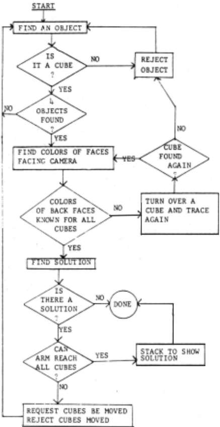
The solution is found using a scheme designed by Feldman which will find a solution, if one exists, in ~uch less time than it would using an exhaustive search. First the colors of each cube are obtained from the associations and a three element set is created for each cube, each element being a digit from 1 to 10 re presenting the two colors on one of the three pairs of opposite faces of the cube.
The heart of this scheme is a 10 by 10 table which is indexed by the encodings for two pairs of opposite faces. The program selects one pair of opposite faces from each of two cubes. The table is used to determine whether or not a solution can exist if the two cubes are stacked so that the selected pair of opposite faces of one can be directly over the selected pair for the other cube, in either of the two possible configurations. If, for example, the pairs are white-white and white-red, one side of the tower already has two white faces. If the table indicates a legal combination , a legal combination is found using another pair of faces from each of the same two cubes. Now we have orientations for two cubes, modulo a 180° rotation about either or both of the axis parallel to the table (since we are considering only pairs, not which face of the pair is on which side).
Then the same procedure is used to get legal orientations for the other two cubes . The table is constructed so that to have a solution for all four cubes, the table entry for each face pair of the one pair of cubes which are to be aligned must equal the negative of the entry for the face pairs of the other pair of cubes which are to be on the same sides of the tower .
The program sequences through the possible combinations until it finds one which gives a solution. Then it fills a 4 x 4 array with the faces of each cube which go on each side of the tower, doing the proper rotations of the cubes to resolve ambiguities between pairs of opposite faces.
If a solution was found, the control pro gram obtains from the solution array the two faces of each cube which make up two adjacent sides of the resulting tower. The vector normal to each of the faces in its current orientation is retrieved from the world model. Using the cross product of the two vectors, the sequence of rotations about the three axes necessary to point the orientation vector up, with the two faces pointing the correct direction, is found . Finally, the arm driver is called to r otate and stack the cubes to demonstrate the solution.
5. FUTURE PLANS
Since the current system can perform its assigned task it is doubtful that a great deal of work will be done with the aim of improving this specific task. Instead, the development of this system has given us a better understanding of the weaknesses of the various modules . Future work will be devoted to eliminating the major weaknesses, replacing the more restrictive modules, and adding new modul es with capabilities not currently available.
A new arm has been built and will soon replace the current one, which is rather slow and inaccurate. A complex body recognizer, which can handle objects partially obscured by other objects, is currently being debugged. Visual feedback is planned to track the objects while the arm is moving them to increase accuracy and prevent objects from being dropped because they were picked up poorly. Until then, the TV will be moved to the area where the object was set down (or dropped) and the scene rescanned to locate it. A new TV camera with less noise is being prepared for use.
A program which can focus the camera has existed for some time and can be incorporated into future systems to enable the camera to view a wider area of the table. It can also be used to provide depth information. Currently, the system uses the ground-plane assumption (i.e. that all objects rest on the table, whose position is known), and it intersects the table plane with the lines from the lens center through the object to find the object'~ position . (10) This method fails if objects are resting on top of each other.
Languages for formulating and implementing strategies are being developed so that even less modification to programs will be needed to change tasks. The next proposed task is to look at a complicated tower composed of blocks of various sizes and shapes and then disassemble it and rebuild it in a different part of the work space.
@inproceedings{ijcai1971p36,
  title     = {The Use of Vision and Manipulation to Solve the "Instant Insanity" Puzzle},
  author    = {Feldman, Jerome A. and Pingle, Karl K. and Binford, Thomas O. and Falk, Gilbert and Kay, Alan C. and Paul, R. and Sproull, Robert F. and Tenenbaum, Jay M.},
  booktitle = {Proceedings of the Second International Joint Conference on
               Artificial Intelligence, {IJCAI-71}},
  publisher = {International Joint Conferences on Artificial Intelligence},
  editor    = {D.C. Cooper},
  pages     = {359--363},
  year      = {1971},
  url       = {https://ijcai.org/proceedings/1971/36},
}
TY - CPAPER TI - The Use of Vision and Manipulation to Solve the "Instant Insanity" Puzzle AU - Feldman, Jerome A. AU - Pingle, Karl K. AU - Binford, Thomas O. AU - Falk, Gilbert AU - Kay, Alan C. AU - Paul, R. AU - Sproull, Robert F. AU - Tenenbaum, Jay M. T2 - Proceedings of the Second International Joint Conference on Artificial Intelligence, IJCAI-71 PB - International Joint Conferences on Artificial Intelligence PY - 1971 SP - 359 EP - 363 UR - https://ijcai.org/proceedings/1971/36 ER -Copied
Machine-readable versions of this paper, for tools and AI agents:





