
A Pattern Classification by the Time-Varying Threshold Method
Proceedings of the First International Joint Conference on Artificial Intelligence. Physiological Modeling. Pages 417-428.
© 1969 International Joint Conferences on Artificial Intelligence
Abstract
An element having the mechanism of timevarying threshold has been proposed by S. Aida and denoted as an IMICTRON. Several applications of the IMICTRON have already been discussed. The most distinguishing property of the IMICTRON is its time-varying threshold level with a function of reintegration, which makes it possible to realize a fuzzy logic, such as required for the dynamic visual-pattern-recognition network discussed here. The other method using the time-varying threshold is named the Varishold method, which is an abbreviation of the variable threshold method. In this system, the threshold is applied in a descrete time, whose level is variable in each sampling time. This paper, therefore, shows the two kinds of the pattern recognition, the one is a visual application that is a classification by the timevaryin~ threshold, and the other a tactile pattern recognition by the descrete variable threshold.
- S. Aida, "Theory and Application of IMICTRON: A Control Element having Mechanisms of a Living Neuron", Report of the Institute of Industrial Science, University of Tokyo, vol.l7, no.5, pp.l57-240, March 1967.
- R.S. Ledley, et al. "Introduction to the Theory of Time Interval Modulation Information Coding System", National Biochemical Research Foundation Report, no. 63051/3265 , May 1965.
- L. D. Harmon, et al. "Studies with Artificial Neurons I,II,III, properties and Functions of Artificial Neurons", Kybernetic, vol.l, December 1961. .
- E.R. Caianiello, "Outline of a Theory of Thought Process and Thinking Machines", J. Theoret. Bioi. vo1.2, no.2, pp.204-234, February 1961.
- S. Aida, "IMICTRON Modulated Learning Control Systems", Proc. of the First Hawaii International Conference on System Sciences, January 1968.
- s. Aida and G.C. Cheng, " A Dynamic Visual- Pattern-Recognition Network of Artificial Neuron", Digest of the 6th International Conference on Medical Electronics and Biological Engineering, no.29-4, August 1965.
References were extracted automatically from the PDF and may contain errors.
Full text extracted automatically from the PDF; figures, tables and equations may differ. The PDF is the version of record.
1. Introduction
An IMICTRON 1 network is characterized by the
fact that information appears in the system, at some points, as a sequence of pulses of identical shape, generally non-equally spaced depending upon the number and period of the preceding pulse pattern, and of a positive sign; and this system is considered to be a new type of information proces sor. The IMICTRON has incorporated the classical axonal properties of temporal summation, time varying threshold with a reintegration, inhibition, refractory time and ali-or-none output .
The name of the IMICTRON came from its mode of coding Time Interval Modulation Information Coding 2(TIMIC or IMIC) . In a TIMIC system, the interval of the output pulse is determined by the past pattern of the output sequences. Therefore, the pulse intervals in IMICTRON networks are dependent upon the input signal and a time-varying threshold level, whereas the pulse intervanls in the PWM ( Pulse Width Modulation) as well as PAM (Pulse Amplitude Modulation) systems may be considered signal-independent.
The authors have proposed here a neurophysio logical On, Off logic, in which the information is processed by a time-varying function that is somewhat fuzzy in comparison with the conventional logical s~stems, and discussed here the pattern recognition for a moving object.
Recently, many results have been presented for the internal structure or information promtntmum level with a certain period and, if no output is emitted within a certain period, the threshold level recovers to the maximum constant threshold level, Qmax as shown in Fig. 2, this property is a reintegration as it is called.
The specifications of the IMICTRON (the IMICTRON networks) presented here. emphasize one of the most interesting aspect of this scheme of modulation, namely, the fact that such an element transmits information in the form of pulses. when it is needed. These properties may be applicable to various fields such as the IMICTRON Modulated feedback control systeml, a learning system4, and a pattern recognition system.
2.2 Modified IMICTRON
The modified IMICTRON is an element which is modified for the purpose of realizing On and Off responses, and a property of Adaptation* in neurophysiology. The authors have defined such models as On- or Off-IMICTRON and so on.
The modified IMICTRON is given the same pro perty of the reintegrative action for the time varying threshold level and its block diagram is shown in Fig. 3. The internal potential of the modified IMICTRON is not reset to zero when the output pulse is emitted. Therefore, the output pulses are continually emitted whenever the comparator's output (C in Fig. 3) is equal to or greater than zero (C2Q).
3. Dynamic Visual-Pattern-Recognition by IMICTRON Networks
3.1 Realization of On, Off and On-Off cell-Nets by Modified IMICTRONs
A~asic concept of On, Off and On-Off responses in a visual receptor is described in the preceding section. Here the authors set out to realize these responses by the TIMIC system and to utilize them in an information processing system. Each of the responses is realized by a modified IMICTRON.
3.1.1 On-IMICTRON: The block diagram of the On IMICTRON is illustrated in Fig. 3. The threshold control pulse generator produces one pulse whose amplitude is m' and width d in the presence of an analog signal from a receptor.
The shape of the threshold control pulse is determined by the property of Q(t) and the input value Q(t).
3.1.2 Off-IMICTRON: The Off-IMICTRON is identical to the Ori-IMICTRON in every respect but a position of the output pulses (see Fig. 5).
3.1.3 On-Off IMICTRON: On-Off IMICTRON can be realized by the threshold control pulse generator providing functions both of On and Off responses. 3.2 Network Organization
In utiltztng the TIMIC system, the network configuration is basically fixed in this kind of connection. For example, the basic circuit of the movement-detection net is shown in Fig. 4. The "On" and "Off" in the circles represent the On and Off-IMICTRON, respectively. It has been noted that the natural response of the IMICTRON to a D.C. input is a non-periodic (asynchronous) sequence of pulses. This system has been con structed consisting of, (a) a receptor cone analog. providing continuous voltage output proportional to the stimulus light. (b) Onand Off-IMICTRONs which transform the signal to the pulse trains representing the "On" and "Off" responses in neurophysiology. (c) a moving spot detector IMICTRON, in the presence of pulse trains of cells #3 or #4 detects the movement in the directions as shown by the arrows. This system cannot detect the direction of movement whose speed or character (alternative moving) is such that both cells generate pulse trains at ·the same time. The visual resolution is determined by the factors of each IMICTRON such as their delay and threshold variables. Furthermore, this connection saves elements compared with the any of the conventional research5 and represents a new information processing system.
* Upon application af a constant stimulus, the frequency of the nerve output pulses was fast and then soon afterward decreased.
In Fig. 4, if a moving spot moves from receptors 1 to 2. the IMICTRON #3 emits several pulses by the summation of the Off- and On IMICTRON during the prescribed time, however cell #4 does not emit enough pulses to recognize the directions or a movement. · These operations are caused by the a·ctions of spa,tial summation with delay to the input pulses and time-varying thresholds of the IMICTRON. After recognized the direction of a movement, when the next moving spot is moved in the opposite direction, if the threshe hold level of cell #3 does not recover enough toward the maximum threshold level, Qmax. both cells #3 and #4 emit several pulses, in this case this system cannot recognize the direction of motion. Therefore. visual resolution depends upon both the delay time for On- or Off-IMICTRON · and the recovery time of the time-varying thresholds of the IMICTRON (cells #3 and #4).
Fig. 5 illustrates the relationships between the outputs of the On- and Off IMICTRONs and the inputs of the IMICTRON cells #3 and #4, respective ly in the case of a light spot moving from recep tors 1 to 2.
During the simulation, each input shown in Fig. 5 is transmitted to as many as 20 Detector IMICTRONs. Each sub-input of the ordinary IMICTRONs (3&4) is a pulse train and its output is assigned by the period and number of the output pulses of the modified IMICTRON. This approach of assigning scattered sub-inputs is influenced by the school of neurophysiologists who emphasize the dendrite reception.
3.3 Results and Interpretation
This experience has indicated that the electronic system is a convenient and useful tool in the formulation and exploration of theoretical models of retina function. This type of simula tion is a more simple configuration and more similar to a living system than any of the mathematical or experimental models for the visual information system. especially the delay time of On- and Off-IMICTRONs.
- Tactile Pattern Recognition Using the VARISHOLD Method
4.1 VARISHOLD Method
The VARISHOLD Method is a shortened form of the variable threshold method. The threshold is applied in a descrete t~Its level is variable in each sampling time. This section shows the method of pattern recognition using the VARISHOLD Method.
It is a matter of universal knowledge that the threshold varies its levels and that a living body has the quality of being adaptable.
"The threshold is a reference level relative to external stimuli, and whose level varies due to circumstance."
This method is to vary the threshold accor ding to the purpose of the system as well as the input of the system.
So to speak, VARISHOLD Method intends that the authors apply a variable threshold of living body to technological system. The threshold is changed. according to time, co-ordinate, and time space. Fig. 6 illustrates some threshold vari ations.
4.2 Construction of Comparator
This comparator compares a given' state, that is, inner-potential with the threshold.

where Ip(t), 9, is inner-potential and thres hold respect1vely, and z is delay time.
4.3 Tactile Pattern Recognition
In general, the objects are recognized as a visual pattern. If the pattern recognition with aid of optical sense is skillfully constructed, artificial finger can be easily used for manipu lator of general purpose machine or hand of robot,
This section discusses a possible technique, that is, the VARISHOLD Method, that is being developed for the recognition of 3-dimensional solid patterns, for example, cubic, edge, plane, etc., with view of its application to the arti ficial finger.
The following steps are considered as the process of artificial finger recognition with tactile sense.
- Taking rough aim at the object scale or form from finger state which is gripping the object.
- Taking the state of the object surface by tactile sense.
- Taking the state of the other surface by changing the ~rip st~te of the finger.
- Recognizing the object from the infor mation of step 1 - step 3.
Main discussion is the surface state of step 2, as shown in Fig. 7. ·
4.4 Technological Model of Tactile Receptor
As shown in Fig. 8, a simple model of tactile receptor is constructed from its physiological one. It is well known that sensory nerve and its ending which serve tactile sense exist in skin. The model eliminates temperature, pain and touch sensation of tactile sense and put a pressure electric transformation element or pressure sensor corresponding to pressure sense.
Moreover, the surroundings of its elements are filled by approximate elastic material. When any object comes in contact with the surface of the model, a strain resulting in elastic defor mation of material transmits to the pressure elastic transformation element, and is converted to electrical signals.
4.5 Construction of Receptor
It is known that the physiological receptor corresponding to pressure sense is the Pacinian corpuscle. Pacinian corpuscles emit impulses according to corpuscle deformation which results from the strain of skin tissue that is caused by the pressure of an object on the skin. There are larger ones (with a length of 850}Land diameter of 500~) in comparison with the other cells. The sensory nerve ending in its corpuscle is surrounded by a lamellated fluid-filled capsule which is dependent on the viscous element.
Therefore, the receptor unit corresponds .to the pacinian corpuscle described above and its unit input constructed as shown in Fig. 9 can be considered as the skin surface or surface of a pacinian corpuscle.
It is suitable for our purpose to treat inner-potential Ip, as the transfer function "G" is apparently complicated.
The globular surface contacting on the surface, Fig. 10 shows the pressure distribution occuring on the receptive field corresponding to a sensory nerve cell group. Its distribution is 3-dimensional.
The response of pressure distribution can be taken by the information for each threshold.
5. Reco~nition of the Pressure Distribution
From t e result of the proceeding section, it is made to recognize the pressure distribution due to the object by using the VARISHOLD Method.
Let R be a region of receptive field and let V(x,y,z) be the distribution of pressure in R, and R, V(x ,y, z), is a subset of 3-dimensional Euclidean space F..
It is clearly shown that,
A set V(x,y,z) is supposed as a convex from the object properties. Moreover, the threshold distribution Q is considered as a plane P (9).
Consider the intersection Xi between V(x,y,z) and P (9):
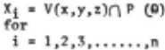
where 9 is taken by the value which Xiis not an empty set.
Namely, P (Qi=l) is taken the supporting hyperplane to V (x,y,z).
Suppose
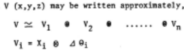
where $ 1 ® is a direct Stun, a direct product, respectively.
Therefore, as a boundary of Xi represents x 8 ., for each i, recognizing these 2-dimensional pa!tern Xsi· that is, periphery pattern of Vi, 3-dimensional pattern V is recognized by the following method.
Pattern V is approximately described by the pattern x 8 i recognized in close succession. For example, the 2-dimensional pattern X~i corres ponding to threshoJd Q is shown in F1g. 11.~
Intersection X between standard plane P and V (x,y,z) is shown by the following:
other. . 1 w
N where p = p (e. = ~). 'a is a small value. P and P (Q · ) are planes and parallel to each
Defining a line 1 parallel to z-axis and a line 1· parallel to i through any point u;of the set X· on the 2-dimensional plane P(Qi), and let u'i b~ a point such that
then, a parallel p~ojection 1 can be defined (see Fig. 10) and denoted
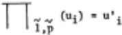
N ]Y the parallel projection of P in the direc tion 1 over the elements of the set Xi, X'i is denoted by
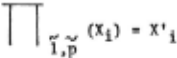
n (X·)= x·.
Subscript i corresponds to the threshold Qi and in the case of the subscript i=l, the plane P (Qi=l) is decided on a supporting hyperplane.
Therefore, the parallel projection for each threshold Qi satisfy the following relation, which ~ows the relationship between a mapped X'i and X for the form of V (x,y,z).
1) Pillared form
A cylinder -----X'i; a circle for each subscript i.
A square pillar----- X'·; a square for each su£script i.
2) pyramidal form or spherical form
A spherical form or circular cone
--- X'i;a circle for each subscript i.
A pyramid ----X' i; a square for each subscript i.
3) Ridge or Hip form
A ridge form---- X'·; a square for each suEscript i.
4) Frustum

Frustum of a cone ----- X'i; a circle for each subscript i.
Frustum of a pyramid -- X'i; a square for each subscript i.
5) Plane

where P, s, vJ -is a point, segment and a small closed plane, respectively.
6. Digital Simulation
Some examples of the pattern have been simulated on a digital computer. Simplified flow diagram of simulation is given in Fig. 12.
The size of the receptive field used for the simulation is a 40 x 40 lattice structure.
A test pressure pattern is the convex set and is generated by solving a pattern equation. The amplitude of the pressure applied on the lattice point is normalized in 10 steps.
The recognition is carried out by the described method which generates the periphery pattern corresponding to each threshold .
The 3-demensional onject, for example, spheri cal form, has been recognized by the relationship between the threshold and its corresponding pattern, that is, circular.
7. Conclusion
This paper has described the application of the IMICTRON, that is a new type of information processing model. In the system described, the time-varying threshold element, IMICTRON proposed by the authors, simulates the neurophysiological phenomena in the single element and reduced to about 50 per cent the elements rieeded for designing a dynamic visual-pattern-recognition network. 5
This paper also discusses the tactile pattern recognition, but this method is not completed and is difficult to apply directly for a machine. However, this pattern recognition is able to carry out easily a part of solid body in comparison with visual sense, if we can realize such a receptor for the machines.
A large scale solid object may be observed by a combination of the described method and the movement of finger tips. Moreover, it may be recognized by a continuous movement of the finger tips. And the VARISHOLD Method will be applied to the various engineering fields.
@inproceedings{ijcai1969p38,
  title     = {A Pattern Classification by the Time-Varying Threshold Method},
  author    = {Aida, Shuhei and Kinoshita, Gen-ichiro},
  booktitle = {Proceedings of the First International Joint Conference on
               Artificial Intelligence, {IJCAI-69}},
  publisher = {International Joint Conferences on Artificial Intelligence},
  editor    = {Donald E. Walker and Lewis M. Norton},
  pages     = {417--428},
  year      = {1969},
  month     = {5},
  note      = {Physiological Modeling},
  url       = {https://ijcai.org/proceedings/1969/38},
}
TY - CPAPER TI - A Pattern Classification by the Time-Varying Threshold Method AU - Aida, Shuhei AU - Kinoshita, Gen-ichiro T2 - Proceedings of the First International Joint Conference on Artificial Intelligence, IJCAI-69 PB - International Joint Conferences on Artificial Intelligence PY - 1969 SP - 417 EP - 428 UR - https://ijcai.org/proceedings/1969/38 ER -Copied
Machine-readable versions of this paper, for tools and AI agents:





