
Process Plan Controllers for Non-Deterministic Manufacturing Systems
Proceedings of the Twenty-Sixth International Joint Conference on Artificial Intelligence. Main track. Pages 1023-1030.
https://doi.org/10.24963/ijcai.2017/142
Keywords
- Knowledge Representation, Reasoning, and Logic: Action, Change and Causality
- Agent-based and Multi-agent Systems: Formal verification, validation and synthesis
Abstract
Determining the most appropriate means of producing a given product, i.e., which manufacturing and assembly tasks need to be performed in which order and how, is termed process planning. In process planning, abstract manufacturing tasks in a process recipe are matched to available manufacturing resources, e.g., CNC machines and robots, to give an executable process plan. A process plan controller then delegates each operation in the plan to specific manufacturing resources. In this paper we present an approach to the automated computation of process plans and process plan controllers. We extend previous work to support both non-deterministic (i.e., partially controllable) resources, and to allow operations to be performed in parallel on the same part. We show how implicit fairness assumptions can be captured in this setting, and how this impacts the definition of process plans.
- [Bi et al., 2008] Zhuming M. Bi, Sherman Y.T. Lang, Weim- ing Shen, and Lihui Wang. Reconfigurable manufacturing systems: the state of the art. International Journal of Pro- duction Research, 46(4):967-992, 2008.
- [Browne et al., 1984] Jim Browne, Didier Dubois, Keith Rathmill, Suresh P. Sethi, and Kathryn E. Stecke. Classifi- cation of flexible manufacturing systems. The FMS maga- zine, 2(2):114-117, 1984.
- [Chaplin et al., 2015] J. C. Chaplin, O. J. Bakker, L. de Silva, D. Sanderson, E. Kelly, B. Logan, and S. M. Ratchev. Evolvable assembly systems: A distributed architecture for intelligent manufacturing. In A. Dolgui, J. Sasiadek, and M. Zaremba, editors, 15th IFAC Symposium on In- formation Control Problems in Manufacturing (INCOM 2015), volume 48 of IFAC-PapersOnLine, pages 2065- 2070, Ottawa, Canada, May 2015. Elsevier.
- [Cimatti et al., 2003] A. Cimatti, M. Pistore, M. Roveri, and P. Traverso. Weak, strong, and strong cyclic planning via symbolic model checking. Artificial Intelligence, 147(1):35 -84, 2003.
- [De Giacomo et al., 2010] Giuseppe De Giacomo, Fabio Pa- trizi, and Sebastian Sardiña. Generalized planning with loops under strong fairness constraints. In International Conference on Principles of Knowledge Representation and Reasoning, pages 351-361, 2010.
- [De Giacomo et al., 2016] Giuseppe De Giacomo, Al- fonso Emilio Gerevini, Fabio Patrizi, Alessandro Saetti, and Sebastian Sardiña. Agent planning programs. Artificial Intelligence, 231:64-106, 2016.
- [de Silva et al., 2016] Lavindra de Silva, Paolo Felli, Jack C. Chaplin, Brian Logan, David Sanderson, and Svetan Ratchev. Realisability of production recipes. In G. A. Kaminka, M. Fox, P. Bouquet, Hullermeijer E., Dignum F., Dignum V., and van Harmalen F., editors, Proceedings of the 22nd European Conference on Artificial Intelligence (ECAI), pages 1449-1457. IOS Press, 2016.
- [de Silva et al., 2017] Lavindra de Silva, Paolo Felli, Jack C. Chaplin, Brian Logan, David Sanderson, and Svetan Ratchev. Synthesising industry-standard manufacturing process controllers. In Proceedings of the International Conference on Autonomous Agents and Multiagent Sys- tems (AAMAS), pages 1811-1813, 2017. Accompanying video available at: https://youtu.be/SEveuikI3p8. Link
- [ElMaraghy, 2005] Hoda A. ElMaraghy. Flexible and recon- figurable manufacturing systems paradigms. International Journal of Flexible Manufacturing Systems, 17(4):261- 276, 2005.
- [Felli et al., 2016] Paolo Felli, Brian Logan, and Sebastian Sardina. Parallel behavior composition for manufactur- ing. In Subbarao Kambhampati, editor, Proceedings of the 25th International Joint Conference on Artificial Intelli- gence (IJCAI 2016), pages 271-278, 2016. IJCAI
- [Koren et al., 1999] Yoram Koren, Uwe Heisel, Francesco Jovane, Toshimichi Moriwaki, G. Pritschow, G. Ulsoy, and H. Van Brussel. Reconfigurable manufacturing systems. CIRP Annals-Manufacturing Technology, 48(2):527-540, 1999.
- [Lu et al., 2014] Yuqian Lu, Xun Xu, and Jenny Xu. De- velopment of a hybrid manufacturing cloud. Journal of Manufacturing Systems, 33(4):551-566, 2014.
- [Mehrabi et al., 2000] Mostafa G. Mehrabi, A. Galip Ulsoy, and Yoram Koren. Reconfigurable manufacturing systems: key to future manufacturing. Journal of Intelligent Manu- facturing, 11(4):403-419, 2000.
- [Nau et al., 2004] Dana Nau, Malik Ghallab, and Paolo Traverso. Automated Planning: Theory & Practice. Mor- gan Kaufmann Publishers Inc., San Francisco, CA, USA, 2004.
- [Rhodes, 2015] Chris Rhodes. Manufacturing: Statistics and Policy. Briefing Paper. House of Commons Library, 2015.
- [Sethi and Sethi, 1990] Andrea Krasa Sethi and Suresh Pal Sethi. Flexibility in manufacturing: a survey. International Journal of Flexible Manufacturing Systems, 2(4):289-328, 1990.
- [Smale and Ratchev, 2009] Daniel Smale and Svetan Ratchev. A capability model and taxonomy for multiple assembly system reconfigurations. In Proceedings of IFAC Symposium on Information Control Problems in Manufacturing, volume 13, pages 1923-1928, 2009.
- [TSB, 2012] A Landscape for the Future of High Value Man- ufacturing in the UK. Technical report, Technology Strat- egy Board, 2012.
References were extracted automatically from the PDF and may contain errors.
Full text extracted automatically from the PDF; figures, tables and equations may differ. The PDF is the version of record.
1 Introduction
Product manufacturing is increasingly moving towards flexible, adaptive, intelligent, and networked manufacturing systems, in which manufacturing activities are distributed, and enterprises collaborate through the so-called manufacturing-as-a-service paradigm [Lu et al., 2014]. In the manufacturing-as-a-service paradigm, each product may be different from the one before (batch size of one production) [TSB, 2012; Rhodes, 2015]. Traditional approaches to production control are unable to meet the demands of manufacturing-as-a-service or batch-size-of-one production. Manufacturing process planning is traditionally carried out by engineers who are experts in the particular processes used in a specific factory, and, with the exception of some limited support by Computer-Aided Process Planning (CAPP) tools, is largely a manual process. From the point of view of manufacturing-as-a-service where the product to be manufactured is not known in advance, the traditional approach has several drawbacks: it requires expensive human expertise to determine whether the customer's product can be manufactured by a given service provider; and even if the product is manufacturable, the small batch sizes (perhaps a single item) mean that manually producing a process plan is uneconomic. To realise the manufacturing-as-a-service vision, process planning must be fully automated, allowing service providers to 'bid' to manufacture products in real time.
To date, there has been relatively little work on the manufacture and assembly of highly-customised products in a highly-networked manufacturing environment. An exception is [de Silva et al., 2016], where techniques are proposed to: (I) determine whether a particular product can be manufactured by a particular set of manufacturing resources (the realisability problem), and (II) how a particular customised product should be manufactured using available resources (the control problem). Their approach takes as input a process recipe specifying the tasks necessary to manufacture the product, and transforms the process recipe into an executable process plan specifying the low-level tasks to be executed by each manufacturing resource in the production line. The resulting process plan is used to orchestrate the activities of agents in the Evolvable Assembly Systems (EAS) architecture, an agent-based architecture for manufacturing control software designed to address rapidly changing product and process requirements including batch-size-of-one customised production [Chaplin et al., 2015]. In EAS, each resource agent represents and controls a manufacturing resource, e.g., a machine tool or a robot.
The approach in [de Silva et al., 2016] relies on several strong assumptions. In particular, it assumes that manufacturing resources are deterministic; that is, the execution of a manufacturing or assembly task from a given state of the system can result in only one possible new state. However many manufacturing resources are non-deterministic in the sense that performing a manufacturing task may result in one of a number of possible states. For example, a moulding operation may result in excess material that must be removed from the moulded part. A second major restriction is that the formalism in [de Silva et al., 2016] prohibits performing manufacturing or assembly tasks in parallel on the same part or set of parts. As a result, they are unable to model, e.g., a flexible assembly cell in which one robot positions or holds a part while another robot performs an operation on the part.
In this paper we extend the approach of [de Silva et al., 2016] to allow non-deterministic resources and tasks to be performed in parallel on the same part, and we define novel notions of process plans and process plan controllers for this setting. Crucially, as we consider non-deterministic resources, their execution may result in cycles that are not under the control of the process plan; therefore, we investigate how implicit fairness assumptions can be captured in this setting, and how this impacts the definition of process plans.
2 Process Recipes
A process recipe specifies the sequence of tasks necessary to manufacture a product, including its constituent parts and associated parameters required to process and assemble these parts into the final product, any tests that must occur during the manufacturing process, and how to respond to test results.
As in [de Silva et al., 2016], we formalise process recipes as labelled transition systems, where labels are complex "task expressions". Let L = ⟨T,C⟩ be a library of tasks where T is a finite set of tasks which represent operations and C is a finite set of part constants. We assume that the set T is partitioned into three mutually disjoint sets: the set of observable tasks Tob which correspond to manufacturing operations; the set of internal tasks Tin, which represent internal actions of the system; and the set of synchronisation tasks Tsyn, which specify the transfer of parts between resources. Specifically, Tsyn = {inh ∣h ∈ N} ∪ {outh ∣h ∈ N} is the set of in and out synchronisation tasks, by which a part is moved from a resource that performs task outh (releasing a part) to the resource that performs task inh (accepting a part). We also use nop to denote idling.
The smallest task expressions are called parameterised tasks (or p-tasks). We extend the formalism of [de Silva et al., 2016] to allow p-tasks of the form t(x,y, z), where t ∈ Tob ∪ Tin, and x,y, z are sequences of part constants in C. The sequences x and y represent the "internal" and "external" inputs of t, respectively, and z represents the outputs. A resource executing task t consumes the parts in x and produces the parts in z, while the parts in y must be present in another resource which consumes them (as input) for its own task. For example, drill(ϵ, c, ϵ) represents a drilling operation performed on a part c that is present in another resource (e.g., a robot drilling a hole in a part held by another robot).
Formally, a task expression is a formula in the language Lang(T ) generated by the grammar:
where ";" denotes a sequence, "∥" denotes parallel composition, and "∣" denotes interleaved composition. We call p-tasks and parallel compositions of p-tasks atomic task expressions. We denote by Langob(T ) the subset of Lang(T ) where every p-task t(x,y, z) ∈ Tob, i.e., only observable tasks are allowed. We impose the following additional constraints on T . Any expression T1∥. . .∥Tm occurring in T is restricted such that each Ti is a p-task and:
- a part constant cannot appear in the inputs x (resp. outputs z) of more than one task; i.e., before (resp. after) parallel tasks are performed on a part, it can only be present in one of their resources; and
- it does not hold that xi,xj = ϵ with zi, zj ≠ ϵ for some i, j ∈ [1,m], i ≠ j, i.e., we disallow introducing more than one "fresh" part into the system (in parallel).

We also restrict task expressions T1 ∣ . . . ∣ Tm occurring in T such that each Ti does not mention the operator "∣".
Definition 1 (Process Recipe). A process recipe is a tuple R = ⟨s0 , S,L, δR⟩, where S is a finite set of states, s0 ∈ S is the initial state, L ⊆ Langob(T ) is a set of task expressions, and δR ⊆ S × L × S is a non-empty transition relation. We denote a transition from state s to s′ , with task expression T , either by s Tleftrightline→s′ or ⟨s, T , s′ ⟩ ∈ δR. ∎
As in [de Silva et al., 2016], process recipes may contain (bounded) cycles, and we assume that cycles are removed by unfolding the recipe up to the bound in a pre-processing step. The unfolded recipe thus describes the (finite) process of manufacturing a given product; when the recipe reaches an end-state with no outgoing transitions the process is "completed". States in the recipe are essentially states in the manufacture of the product that are 'choice points', i.e., where a decision must be made at run-time what to do next based on, e.g., the specification of the current product instance (such as its colour) or testing the partially assembled product. Note that δ is a relation: in general, there may be more than one outgoing transition from each state, because a recipe may encode different alternatives to reach an end-state from the initial state s0 . We generalise [de Silva et al., 2016] by allowing different outgoing transitions, labelled with the same task expression, from the same state of the process recipe.
Figure 1 shows an example of a process recipe (based on [de Silva et al., 2016]) that specifies how to assemble a hinge. The first and second p-tasks load a new pallet fixture (f) and separate it into its constituents: the hinge pin (p) and hollow hinge (h). Then p is glued onto the hinge h to obtain a (non-hollow) hinge (h2), which is then engraved with a serial number. The next two (parallel) tasks involve a 360 degree visual test on h2, after which the recipe either requests a force test, or discards the hinge, depending on the runtime outcome of the visual test. Similarly, the hinge can be stored or discarded, depending on a further force-test (as these tests are performed at runtime, all alternatives must be accounted for).
3 Non-Deterministic Resources
We model manufacturing resources in the facility as labelled transition systems, and extend [de Silva et al., 2016] by allowing non-deterministic transitions.
Definition 2 (Resource). A resource is a tuple R = ⟨s0 , S, T,Leftrightline⇒⟩, where S is a set of states, s0 ∈ S is the initial state, T is the set of tasks, and δR ⊆ S × T × S is a transition relation. ∎
We write s t Leftrightline⇒s′ to denote a transition from s to s′ by task t. For example, resource R1 in Figure 2 can load new pallets. Loading is a non-deterministic transition as it may result in the pallet being misaligned; when this happens, an acoustic signal instructs the operator to realign the pallet. The pallet can then be either stored, removed, or moved to another resource (out1). Transfer of parts between resources is performed by resource R5, which models a transportation system specifying the "legal routes" between production resources.
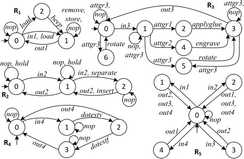
A (production) topology represents the synchronous execution of a set of resources, including where parts are processed and how parts are moved between resources.
Definition 3 (Topology). Let {R1, . . . ,Rn} be resources, with each Ri = ⟨s0i ,Si ,T,Leftrightline⇒i⟩. A topology is a tuple P = ⟨s0 ,S,T n ,Leftrightline⇒⟩, where S = S1 ×⋯×Sn is the set of states; s0 = ⟨s01 , . . . , s0n ⟩ is the initial state; T n is the set of concurrent tasks; and the transition relationLeftrightline⇒⊆ S×T n ×S is such that s t Leftrightline⇒s′ iff for all i ∈ [1,n]1 either:
- ti /∈ Tsyn and si ti Leftrightline⇒i s′i , i.e., resource Ri can execute ti;
- ti ∈ Tsyn and si ti Leftrightline⇒i s′i , and there exists exactly one j ∈ [1,n] such that sj tj Leftrightline⇒j s′j with tj = inh and ti = outh for some h, denoted tj ↢ ti, or the opposite, denoted tj ↣ ti. ∎
The second condition checks that, within a transition, each out task is matched with an in. A transition s t Leftrightline⇒s′ is said to be observable iff at least one task in the vector is observable.
Given a topology ⟨s0 , S, T n ,Leftrightline⇒⟩, the assignment of parts to resources during production is represented by a resource vector r = ⟨c1, . . . , cn⟩, where each ci ∈ C ∗ is a (possibly empty) sequence of parts that do not appear anywhere else in r. We denote ci by r(i) for i ∈ [1,n]; the set of all possible resource vectors as V ; and the empty vector as r0 = ⟨ϵ, . . . , ϵ⟩. Hence, r(i) denotes the parts allocated to resource Ri in the current state of the topology. We note that each element in r is a sequence and not a set, i.e., order matters when moving parts between resources, or when executing tasks on parts. We address a limitation in [de Silva et al., 2016] by allowing the simultaneous execution of tasks on the same parts, in order to model "joint" tasks. A resource Ri currently in state si can execute an (atomic) p-task t(x,y, z) iff (I) the task t
is available from state si in Ri, and (II) the input parts are currently assigned to the resource, and, if external parts are required (i.e., y ≠ ϵ), then there exist one or more other resources to which those parts are collectively assigned. After executing t, parts in z are allocated to the resource. For example, the task insert into(c1, c2, ϵ) inserts part c1 into part c2, where c2 is currently assigned to another resource, and does not produce any parts. Given a p-task t(x, y, z), we denote x by in(t), y by ext(t) and z by out(t).
We now give a formal definition of simultaneous tasks. Let T = t1∥. . .∥tm be a task expression, r a resource vector, s a topology state, and s t Leftrightline⇒s′ a transition with t = ⟨t′1 , . . . , t′n ⟩. Let I = {i ∈ [1,n] ∣ t′i ∈ Tob} be the "observable indices" of t. Then, we say that a resource vector r′ is an allocation of T to t with respect to r, denoted r′ = AL(r, T , t), iff for all i ∈ [1, n]∖I we have r′ (i) = r(i), and there exists a bijection f ∶ I ↦ [1,m] s.t. for all i ∈ I, we have that j = f(i) implies
- tj = t′i , namely the task label in position i in the vector is equal to the task label of the j-th parallel p-task; and
- r(i) = in(tj), r′ (i) = out(tj) and ext(tj) ≠ ϵ iff there exists a subset of indices I ′ ⊆ [1,n] ∖ {i} such that ext(tj) is a concatenation of each in(tk), k ∈ I ′ .
Intuitively, an allocation of T to a topology transition labelled with vector t returns the new resource vector resulting from the simultaneous execution of each task in t, provided that all the p-tasks in T are matched to an observable task in t. For instance, a vector of tasks t = ⟨hold,nop, engrave⟩ can execute a parallel task expression T = engrave(ϵ, c, ϵ)∥ hold(c, ϵ, c), so that ⟨c, ϵ, ϵ⟩ = AL(⟨c, ϵ, ϵ⟩, T , t). For sequences of the form T1; T2 we can compute allocations recursively, and for interleaved compositions of the form T1 ∣ T2, we need to find a linearisation such that an allocation exists. Details are omitted for brevity, as they do not differ from [de Silva et al., 2016] apart from the base case above.
For synchronisation tasks, a resource vector r′ is a transfer of parts from r via t, denoted r′ = MOV(r, t), if for each i ∈ [1, n] we have (I) ti ↢ tj and r′ (i) = r(i) ⋅ c with r(j) = c ⋅ c; or (II) ti ↣ tj and r′ (i) = c with r(j) = c ⋅ c; or (III) r′ (i) = r(i) otherwise. For example, if r = ⟨c, ϵ, ϵ⟩ then MOV(r, t) with t = ⟨out1 , nop, in1 ⟩ is ⟨ϵ, ϵ, c⟩.
4 Realisability of Recipes
Each transition in a process recipe is labelled with a task expression, but these tasks are not directly executable: actual realisations, in the form of "orchestrations" of the topology, must be found. We now introduce some technical definitions.
A trace of a topology P from a resource vector r0 is a sequence τ = σ0 t1 Leftrightline⇒σ1 t2 Leftrightline⇒⋯ such that for each i ≥ 0 we have σi = (si , ri), where si is a state in the topology and ri is a resource vector. A trace represents the evolution of the topology, together with the new resource vector computed at each step. We call a finite trace history, and given a history τ = σ0 t1 Leftrightline⇒⋯ tm Leftrightline⇒σm of length m, we denote σm by last(τ). Unless otherwise specified, we assume s0 = s0 and r0 = r0 , i.e., we take as initial the initial state of the topology and the empty resource vector.
We now introduce the notion of plan, which compactly represents the set of histories (there may be more than one, as the topology is non-deterministic) that realise a given task expression. Let H denote all possible histories of P. Then, a history-based plan is a partial function
which maps a history of P to a vector of tasks. A trajectory of a plan π on P from σ0 is a trace τ = σ0 t1 Leftrightline⇒σ1 t2 Leftrightline⇒⋯ of P, of length ℓ ≥ 0, such that ti+1 = π(τ ∣i), where τ ∣i denotes the fragment of τ of length i ∈ [0,m- 1]. Given a history τ, we call σ∣τ∣ = last(τ) the outcome of τ from σ0. A trajectory of π is said to be complete with respect to π iff it is finite and cannot be extended further, namely, iff π(τ) is undefined.
4.1 Strong Cyclic Plans
A history-based terminating plan is a plan such that all its trajectories are finite, i.e., it always terminates irrespective of the non-determinism of the topology. However, not all trajectories are finite. For example, in Figure 2, the resource R3 encodes a robotic arm which can perform various operations by attaching different grippers. Since performing the internal task attgr3 in state 1 may lead to two possible successor states, there is no history-based terminating plan that is guaranteed to realise the recipe, as the observable task rotate may never be reached. In reality, while performing a task may occasionally take a resource into an abnormal state, resources are engineered such that after a 'small' number of retries and/or some recovery steps, the intended state will be reached. 2 This 'fairness assumption' is however not captured explicitly in the resource or the topology.
Note that the appropriate notion of fairness for manufacturing resources does not correspond to strong fairness as in [De Giacomo et al., 2010], where if the action is repeated infinitely often, then any outcome happens infinitely often. First, while internal tasks such as attgr3 can be non-deterministic, observable tasks such as rotate are assumed to be deterministic: executing the task is assumed to lead to the intended state-otherwise the author of a process recipe would have to anticipate all possible failures of the (unknown) manufacturing resources used to manufacture the product. In this sense, fairness is only relevant to internal tasks, as only internal tasks forming part of the 'implementation' of an observable task may be retried: e.g., repeatedly executing attgr3 will eventually reach a state where rotate can be executed. Second, repeating an observable task would violate the recipe, and in many cases this would be incorrect and/or unsafe (consider, for instance, operations such as casting or moulding). Third, parts/subassemblies often represent considerable investment of materials and process steps, so are usually only discarded as a last resort. As observable tasks may be non-deterministic in practice, a controller may have to implement a 'recovery' internal plan fragment to remedy undesired states (e.g., to remove excess material from a moulded part when required) prior to the next observable task in the recipe. Hence, we need to relax strong fairness, and consider a particular kind of strong cyclic plan [Cimatti et al., 2003] whose associated trajectories can always terminate, and when they do, are guaranteed to achieve the goal.
2 Note that there is no restriction in our formalism that the number of retries should be small.
4.2 Process Plans
We can now concretise our definition of process plan, which represents a strong cyclic history-based plan. First, we say that a history-based plan π is nonblocking if any of its finite trajectories can be extended to a complete trajectory (namely, it is a prefix of a complete trajectory of π). Thus, it is always possible for these plans to terminate. However, they are not necessarily terminating plans, as they may have infinite trajectories. To be implementable in practice, we need to find a finite representation of such plans.
Definition 4 (Process plan). Given a task expression T , a topology state s0 and a resource vector r0, we say that a history-based plan π is a process plan for T from (s0 , r0) iff π is nonblocking and any complete trajectory of π from (s0 , r0) realises T , as defined below.
Informally, a trajectory τ realises an atomic task expression T iff the task is allocated in (exactly) one step, which is necessarily an observable transition, while all other steps are arbitrary unobservable transitions (i.e., consisting only of internal tasks and synchronisation tasks). Formally, given a plan π, an initial state s0 and a resource vector r0, a trajectory τ = σ0 t1 Leftrightline⇒⋯ tm Leftrightline⇒σm of π from σ0, with σi = (si , ri) for each i ∈ [1,m] realises an atomic task expression T iff:
- there exists an ℓ ∈ [1,m] such that rℓ = MOV(r, tℓ) with r = AL(rℓ-1, T , tℓ);
- for any other j ≠ ℓ, j ∈ [1,m], we have that tj is unobservable and rℓ = MOV(rℓ-1, tℓ).
We extend this notion to sequences, and say that a trajectory τ realises a task expression of the form T1; T2 iff τ has the form τ = τ1 ⋅ τ2 and τ1 (resp. τ2) realises T1 (resp. T2), where τ1 ⋅ τ2 denotes the concatenation of two finite trajectories sharing the last and first state, respectively (which is equal to τ1 when τ2 is the empty trajectory). The extension to interleaved compositions is analogous, by considering all possible linearisations. Without loss of generality, we assume that an observable transition is always the last one in the trajectory, as this strictly relates plans to the task expressions that they realise by disallowing subsequent arbitrary transitions (which, instead, should be executed to realise the next task expression in the recipe).
As process plans are not necessarily terminating, they may have infinite trajectories. We therefore introduce finite representations of such plans. First, given a history τ, its contractions, denoted acycl(τ), is the set of histories obtained from τ by removing all cycles. The contractions correspond to the fixpoint of an operator λ on {τ } defined as τ1 ⋅ τ2 ∈ λ({τ, ⋯}) iff τ = τ1 ⋅ τ ′ ⋅ τ2, such that the first and last state of τ ′ are the same, i.e., last(τ1) = last(τ ′ ). It is trivial to see that a contraction always exists. A basic plan is a partial function
that is defined only for acyclic histories Ha ⊆ H of P (which are finite), and thus only generates finite and complete trajectories. We say that πb is a basic plan for T iff every acyclic trajectory of πb that is complete realises T , and at least one such trajectory exists. These plans can be represented and implemented finitely; however, they are not process plans: they do not need to realise any task, and indeed in a nondeterministic topology they may not do so. Given a basic plan πb, we can reconstruct a generic history-based plan π{πb} as follows:
where τ ′ is a trajectory of πb and τ ′ ∈ acycl(τ). Informally, πb is applied to τ by disregarding any cycle.
Theorem 1. If πb is a basic plan for T and π{πb} is nonblocking, then π{πb} is a process plan for T .
Proof Sketch. It is easy to see that πb is defined for every contraction of one of its trajectories that still does not realise T . This holds trivially for acyclic trajectories, since they must realise the task expression by definition. For cyclic trajectories, assume that for a contraction τ ′ , πb(τ ′ ) is undefined. Then τ ′ is not a trajectory of πb (which is instead required) otherwise, being complete, it would contradict the fact that every complete acyclic trajectory realises T . Hence any cyclic trajectory of π{πb} can always be extended to one that is finite and complete. Thus π{πb} is nonblocking, which together with the hypothesis proves the claim. ◻
Basic plans are memory bounded, and as soon as they induce a cyclic trajectory, they immediately "reset" to a contraction. However, not every process plan can be reconstructed from a given basic πb (e.g., a process plan that prescribes a different action for the same cyclic behaviour of the system when the number of cycles is a prime number). Nevertheless, the result above is crucial for computing the "correct" set of basic plans πb for a task expression T (i.e., those where π{πb} is nonblocking). It can be shown that from the set of all basic process plans ¯Π = {π1, . . . , πq} for a task expression T such that π{πi} is nonblocking, we can reconstruct any process plan π for T . The proof of this claim is involved and we omit it due to lack of space, as it is not needed to prove the correctness of our approach. Rather it supports (in addition to Theorem 1) the intuition that basic plans represent the minimum information required to reconstruct process plans. Intuitively, a process plan for T can be reconstructed from ¯Π by means of a function f ∶ H ↦ ∣¯Π∣ that prescribes, at each step of the current trajectory τ , which basic plan πf(τ) to use.
4.3 Process-Plan Simulation Relation
In this section, we capture the ability to realise transitions in the recipe as a property relating states of the recipe with states of the topology and resource vectors.
Definition 5. Let P = ⟨s0 ,S,T,Leftrightline⇒⟩ be a topology and R = ⟨s0 , S, L, δR⟩ a recipe. A process-simulation relation is a relation PSIM ⊆ S×S×V , 3 such that a tuple ⟨s, s, r⟩ ∈ PSIM implies that for any T , if s Tleftrightline→s′ for some s′ , then there exists a process plan π such that for each complete trajectory τ of π from (s, r), we have that (I) τ realises T (as defined above); and (II) ⟨s′ , s′ , r′ ⟩ ∈ PSIM, where (s′ , r′ ) = last(τ).
3 Recall that V is the set of all resource vectors.
Thus, a state s of a recipe R is said to be process-simulated by a state s of a topology P with respect to a resource vector r if there exists a process-simulation relation PSIM such that ⟨s, s, r⟩ ∈ PSIM. Moreover, R = ⟨s0 ,S,L, δR⟩ is processsimulated by P = ⟨s0 ,S,T,Leftrightline⇒⟩ if s0 is process-simulated by s0 with respect to r0 .
The definition states that no matter how the recipe evolves from s (according to transition choices made by runtime tests), there exists a process plan whose complete trajectories realise the requested task expression. Crucially, the process recipe cannot control which particular trajectory of the process plan is followed, as the topology is non-deterministic.
Definition 6 (Realisability of a recipe). Given a state s0 and a resource vector r0, a recipe R = (s0 , S, L, δR) is realisable from (s0 , r0) iff there exists a function ω ∶ S ×V ×δR ↦ Π such that:
- for each transition s0 Tleftrightline→s′ in R, the plan ω(s0 , r0, s0 Tleftrightline→s′ ) = π is defined and it is a process plan for T from (s0 , r0);
- if ω(s, r, s Tleftrightline→s′ ) = π is defined, then
- π is a process plan for T from (s, r); and
- for each outcome (s′ , r′ ) of a complete trajectory τ of π from (s, r), and for each s′ T ′ leftrightline→s′′ in R, we have that ω(s′ , r′ , s′ T ′ leftrightline→s′′ ) is defined. ∎
Recall that if π is a process plan for T from σ, then any complete trajectory of π from σ realises T . Finally, a recipe R is realisable in a topology P = ⟨s0 ,S,T,Leftrightline⇒⟩ if R is realisable from (s0 , r0 ). The above definition only requires the existence of a function ω which returns a possible "correct" plan at each step. The notion of realisability in a topology is closely related to the notion of plan-based simulation in [De Giacomo et al., 2016] and T -realisation in [De Giacomo et al., 2010]. However, unlike that setting, we do not consider a planning domain due to the high modularity of our setting, as well as the presence of various low-level details (such as resource vectors and simultaneous tasks).
Theorem 2. A process recipe R is realisable in a topology P iff P process-simulates R.
Proof Sketch. Given (s, r), assume that a function ω as above is defined for each s Tleftrightline→s′ in R, namely, ω(s, r, s Tleftrightline→s′ ) = π, but P does not process-simulate R. By Def. 5 this implies that there is no process plan, including π, such that each of its complete trajectories τ realise T , or the ⟨s′ , s′ , r′ ⟩ /∈ PSIM with (s′ , r′ ) = last(τ). These two cases violate the first and second item of Def. 6, respectively; hence, ω does not exist. If instead ⟨s0 , s0 , r0 ⟩ ∈ PSIM, then, by definition, there exists a plan π as in Def. 5 for each s0 Tleftrightline→s′ in R; hence, we can build the function ω so that ω(s0 , r0 , s0 Tleftrightline→s′ ) = π. The same argument can be applied by induction on ⟨s′ , s′ , r′ ⟩, where (s′ , r′ ) is the outcome of any complete trajectory of π, as ⟨s′ , s′ , r′ ⟩ ∈ PSIM by hypothesis. ◻
4.4 Process Plan Controllers
Intuitively, a process plan controller encodes a set of functions ω as in Definition 6, i.e., a function that associates at least one process plan to each transition (task expression) of a recipe, such that for each possible resulting trajectory, the function can still associate another process plan as the recipe is progressed forward. We use a finite-state representation based on the notion of process-plan simulation relation.
Definition 7. Given a topology P and process recipe R, a process plan controller for R = ⟨s0 , S, Lang(T ), δR⟩ in P is a tuple C = ⟨PSIM, δR, Π, δ⟩ with:
- PSIM ≠ ∅ is a process plan-simulation relation, whose elements correspond to the set of states in the controller;
- δR is the recipe transition relation;
- Π is a set of process plans;
- δ ∶ PSIM×δR×Π×PSIM is a transition relation, defining transitions from one state to another, by executing a process plan π that realises a task expression T . A transition ⟨s′ , s′ , r′ ⟩ ∈ δ(⟨s, s, r⟩, tr, π) exists for tr = s Tleftrightline→s′ , also denoted ⟨s, s, r⟩ tr,π leftrightlineleftrightline→⟨s′ , s′ , r′ ⟩, iff s Tleftrightline→s′ is in δR and:
- π is a process plan for T , i.e., it is nonblocking and all complete trajectories of π realise T ;
- a complete trajectory τ of π exists from (s, r) with (s′ , r′ ) = last(τ), and for any complete trajectory τ ′ of π from (s, r) with (s′′ , r′′ ) = last(τ ′ ), we have ⟨s, s, r⟩ tr,π leftrightlineleftrightline→⟨s′′ , s′ , r′′ ⟩. ∎
As a direct consequence of Theorem 2 and the definition of process plan controller, we get the following result.
Theorem 3. A recipe R is realisable in a topology P iff there exists a process plan controller for R in P.
Proof Sketch. It follows by construction of the process plan controller C. It is possible to compute the function ω in Definition 6 as follows: ω(s, r, s Tleftrightline→s′ ) = π iff ⟨s, s, r⟩ tr,π leftrightlineleftrightline→⟨s′ , s′ , r′ ⟩, considering tr = s Tleftrightline→s′ . Indeed by Theorem 2 if ⟨s, s, r⟩ ∈ PSIM then ω(s, r, s Tleftrightline→s′ ) is defined for every recipe transition s Tleftrightline→s′ . ◻
5 Computing Basic Plans
In this section, we provide an algorithm that computes a process-plan simulation relation given a process recipe R and a topology P, and in doing so also computes a process plan controller for R and P. We extend the algorithms in [de Silva et al., 2016] to handle non-deterministic topologies and to compute a set of basic plans, having the property as in Theorem 1, for each transition of the process recipe. By the theorem, these can be used to reconstruct history-based plans.
Given a process recipe R, a topology P, a state s of P, a resource vector r and a state s of R, Algorithm 1 determines, for each transition tr = s Tleftrightline→s′ , whether there exists a basic plan for T from (s, r), and in turn, whether the same holds for each transition from s′ (as required by Definition 6). To this end, tr is passed as a parameter to Algorithm 2 to continue checking from s′ . We use π0 b to denote the empty plan.
Algorithm 2 uses two auxiliary functions: given a task expression T = T1; T2; . . . ; Tn with n > 0, the first element of T is defined as FST(T ) = T1 and the rest of its elements as
Algorithm 1 FINDSIM(R, P, s, r, s)
Input: a process recipe R = (s0 , S, L, δR), a topology P, the topology state s, resource vector r and recipe state s.
- 1: δ, δ′ , PSIM, PSIM′ := ∅
- 2: for each recipe transition tr = (s, T , s′ ) ∈ δR do
- 3: (PSIM′ , δ′ ) := EVAL(R,P, T , tr, (s, r),π0 b , (s, r), ∅)
- 4: if PSIM′ = ∅ then return (∅, ∅)
- 5: PSIM := PSIM∪ PSIM′ ; δ := δ ∪ δ′
- 6: return (PSIM∪ {(s, s, r)}, δ)
Algorithm 2 EVAL(R, P, Tcur , tr, τ, πb, σ0, Σ)
Input: a process recipe R, a topology P = (s0 ,S,T n ,Leftrightline⇒), the current task expression Tcur and recipe transition tr = (s, T , snxt), the current trajectory τ and basic plan πb, the initial couple σ0 = (s0 , r0) and the visited couples Σ. 1: σ↓ := (s↓ , r↓) := last(τ) 2: (PSIM, δ) := (∅,∅) 3: if Tcur = ϵ then 4: x := (s0 , s, r0) tr,πb leftrightlineleftrightlineleftrightline→(s↓ , snxt , r↓) 5: (PSIM, δ) := FINDSIM(R,P, s↓ , r↓, snxt) 6: return (PSIM, δ ∪ {x}) 7: if σ↓ ∈ Σ then return ({σ↓},∅) 8: σfst := ϵ 9: for each t such that (s↓ , t, s) exists inLeftrightline⇒do 10: (PSIMt, δt) := (∅,∅) 11: if t is observable and r′ = AL(r↓, FST(Tcur), t) then 12: for each (s↓ , t, s) ∈ Leftrightline⇒ do 13: σ := (s, MOV(r′ , t)) 14: πb(τ) := t 15: (PSIMs, δs) := EVAL(R,P, RST(Tcur), tr, τ t Leftrightline⇒σ, πb, σ0, ∅) 16: if PSIMs = ∅ then (PSIMt, δt) := (∅, ∅); break 17: else (PSIMt, δt) := (PSIMt ∪ PSIMs, δt ∪ δs) 18: end for 19: (PSIM, δ) := (PSIM ∪ PSIMt, δ ∪ δt) 20: else if t is unobservable then 21: for each (s↓ , t, s) ∈ Leftrightline⇒ do 22: σ := (s, MOV(r↓, t)) 23: πb(τ) := t 24: Σ′ := Σ∪ {σ↓} 25: (PSIMs, δs):=EVAL(R,P, Tcur , tr, τ t Leftrightline⇒σ, πb, σ0, Σ′ ) 26: if PSIMs = ∅ then 27: (PSIMt, δt) := (∅,∅); σfst := ϵ; break 28: else if PSIMs = {σ′ } and δs = ∅ then 29: σfst := EARLIER(σfst ,σ′ , τ) 30: else (PSIMt, δt) := (PSIMt ∪ PSIMs, δt ∪ δs) 31: end for 32: (PSIM, δ) := (PSIM ∪ PSIMt, δ ∪ δt) 33: end for 34: if PSIM ≠ ∅ then return (PSIM, δ) 35: else if σfst /∈ {ϵ, s↓ } then return ({σfst},∅) 36: else return (∅,∅)RST(T ) = T2; . . . ; Tn if n > 1, and as RST(T ) = ϵ if n = 1. Intuitively, Algorithm 2 performs a depth-first search of the topology to check whether there exists a basic plan for the task expression Tcur (initially T ) from σ↓. In particular, the outer loop (lines 9 to 33) considers each unique label t in the outgoing topology transitions from s↓ ; lines 11 to 19 apply if t is observable and the first task in Tcur can be allocated to it, and lines 20 to 32 apply if t is unobservable.
For each observable transition associated with a particular label t, lines 12 to 18 prescribe the following. First, the "successor" couple σ = (s, r) is created to represent the allocation of Tcur to t, and the movement of parts via synchronisations. Second, line 14 updates the plan πb with the vector t labelling the topology transition (s↓ , t, s); this plan is then passed as a parameter in the recursive call to EVAL. Finally, if the rest of the tasks in Tcur cannot be realised from σ, all non-deterministic transitions labelled with t are disregarded. Otherwise, new tuples in PSIMs and the corresponding controller transition δs for t are stored (line 17), and the loop continues. If t is unobservable, the steps are similar to those described above, except for lines 28 and 29. Line 28 applies to the case in which τ t Leftrightline⇒σ constitutes a cycle "back" in the current trajectory τ (i.e., line 7 was executed in the recursive call at line 25): if this is the case, then we compare σ′ with the state σfst (initially the empty string) which is the "earliest" state that is possible to reach, through cycles, from the current topology state s↓ . The intuition is as follows: we need to make sure that there exists the possibility, from σ↓, to cycle back to a state σfst from which it is still possible to find a complete trajectory whose execution allocates the task expression Tcur . If this is the case, then the cycle in the current trajectory of plan πb is "admissible": it (still) guarantees the nonblocking condition of the plan π{πb}. Formally, we define the function EARLIER(σ1, σ2, τ) = σ1 if σ1 occurs before σ2 in τ (or σ2 = ϵ), and EARLIER(σ1,σ2, τ) = σ2 if σ2 occurs before σ1 in τ (or σ1 = ϵ). Then (PSIM, δ) is returned in line 34, consisting of the simulation relations and corresponding controller's transitions. Otherwise, we must rely on there being a state that appears in τ before s↓ , and possibly as early as σfst , from where a complete trajectory can be found and the task allocated. Thus, we "propagate back" σfst until we can exit the current cycle, or until the recursive step is reached with σ↓ = σfst , from where an exit must then exist if a nonempty simulation relation is to be returned. Line 7 checks whether the algorithm has reached a couple σ↓ visited earlier, and if so returns it, guaranteeing that the plan is bounded.
A variant of this algorithm for deterministic topologies has been implemented as part of an agent based control architecture for manufacturing, designed to address rapidly changing product and process requirements [de Silva et al., 2017]. Within this architecture, a process plan controller is used to select basic plans for task expressions that appear in the recipe. Such plans are represented in the Behaviour to Markup Manufacturing Language (B2MML) ISA-95 standard, which is a format that is interpretable by real-world manufacturing execution systems. The implementation also takes into account additional details such as parameters and materials, which have been omitted in this paper.
6 RelatedWork
The problem we consider has similarities with AI planning [Nau et al., 2004; Cimatti et al., 2003]. We adopted a synthesis-based approach due to the difficulties of encoding process recipes and production topologies as planning goals and planning domains. In our setting, there are several features that make such an encoding difficult, including conditional goals (in the recipe), interleaved and parallel tasks.
The notion of process plan controller is closely related to other approaches. For example agent planning programs [De Giacomo et al., 2010; 2016] are finite-state programs where transitions prescribe propositional achievement and maintenance goals that must be realised on a planning domain by implementing each transition via a conditional plan. The solution approach is based on restricted forms of LTL synthesis, and is able to cope with non-deterministic propositional planning domains with explicit fairness constraints, thus producing strong cyclic plans. However, as explained in Section 4.1, the manufacturing setting has a number of features which preclude a straightforward application of this approach, and standard notions of strong cyclic planning cannot be applied.
Our notion of a terminating plan is also similar to historybased terminating plans in [De Giacomo et al., 2016], and related to the notion of (memoryless) strong acyclic plans [Cimatti et al., 2003]. As we explain in Section 4.1, our approach differs from [De Giacomo et al., 2016] in that the trajectories we consider are not finite. Similarly, the state-action table representation used for strong acyclic plans in [Cimatti et al., 2003] is insufficiently flexible for process plans, as it is memoryless, whereas in our setting we must choose actions based on the current history (evolution of the topology) rather than simply the current state of the topology.
Over the last decade there has been a growing body of work on automation to achieve flexibility, resilience, and monitoring in manufacturing. For example, Flexible Manufacturing Systems [Browne et al., 1984; Sethi and Sethi, 1990; ElMaraghy, 2005] increase the variety of parts and products that can be produced, while Reconfigurable Manufacturing Systems [Bi et al., 2008; Koren et al., 1999; Mehrabi et al., 2000; Smale and Ratchev, 2009] allow more rapid response to market changes for a certain product family. In [Felli et al., 2016] an approach is presented to the synthesis of controllers capable of producing multiple instances of the same product simultaneously. However, as none of this work has addressed the manufacture of products in the context of manufacturing as a service, nor considered fairness assumptions or differentiated observable and unobservable tasks, they are restricted to acyclic plans when resources are non-deterministic.
7 Conclusions and FutureWork
We extended previous approaches to the realisability and control problems for process recipes in manufacturing systems consisting of non-deterministic resources, and where operations can be performed in parallel on the same part. We formally defined the notions of process plans and process plan controllers for these systems, where loops in plans must be allowed due to intrinsic fairness assumptions. In this paper we assume that a manufacturing facility is always initially in the initial state of the topology with an empty resource vector. In future work, we plan to relax this assumption and generalise our approach to consider an arbitrary initial state, where parts are already assigned to resources, and the topology is currently being orchestrated to realise another process recipe.
@inproceedings{ijcai2017p142,
  title     = {Process Plan Controllers for Non-Deterministic Manufacturing Systems},
  author    = {Felli, Paolo and de Silva, Lavindra and Logan, Brian and Ratchev, Svetan},
  booktitle = {Proceedings of the Twenty-Sixth International Joint Conference on
               Artificial Intelligence, {IJCAI-17}},
  publisher = {International Joint Conferences on Artificial Intelligence Organization},
  editor    = {Carles Sierra},
  pages     = {1023--1030},
  year      = {2017},
  month     = {8},
  note      = {Main track},
  doi       = {10.24963/ijcai.2017/142},
  url       = {https://doi.org/10.24963/ijcai.2017/142},
}
TY - CPAPER TI - Process Plan Controllers for Non-Deterministic Manufacturing Systems AU - Felli, Paolo AU - de Silva, Lavindra AU - Logan, Brian AU - Ratchev, Svetan T2 - Proceedings of the Twenty-Sixth International Joint Conference on Artificial Intelligence, IJCAI-17 PB - International Joint Conferences on Artificial Intelligence Organization PY - 2017 SP - 1023 EP - 1030 DO - 10.24963/ijcai.2017/142 UR - https://doi.org/10.24963/ijcai.2017/142 ER -Copied
Machine-readable versions of this paper, for tools and AI agents:





