
Generating Tests for Robotized Painting Using Constraint Programming
Proceedings of the Twenty-Fifth International Joint Conference on Artificial Intelligence. Pages 4200-4203.
© 2016 International Joint Conferences on Artificial Intelligence
Abstract
Designing industrial robot systems for welding, painting, and assembly, is challenging because they must perform with high precision, speed, and endurance. ABB Robotics has specialized in building highly reliable and safe robotized paint systems using an integrated process control system. However, current validation practices are mainly limited to manual test scenarios, which makes it difficult to exercise important aspects of a paint robot system, such as the need to coordinate the timing of paint activation with the robot motion control. To address these challenges, we have developed and deployed a cost-effective, automated test generation technique aimed at validating the timing behavior of the process control system. The approach is based on a constraint optimization model written in Prolog. This model has been integrated into an automated continuous integration environment, allowing the model to be solved on demand prior to test execution, which allows us to obtain the most optimal and diverse set of test scenarios for the current system configuration.
- [Balck et al., 2014] Kenneth Balck, Olga Grinchtein, and Justin Pearson. Model-based protocol log generation for testing a telecommunication test harness using CLP. In Design, Automation and Test in Europe Conference and Exhibition (DATE), 2014, pages 1-4, March 2014.
- [Carlsson et al., 1997] Mats Carlsson, Greger Ottosson, and Björn Carlson. An open-ended finite domain constraint solver. In Hugh Glaser, Pieter Hartel, and Herbert Kuchen, editors, Programming Languages: Implementations, Log- ics, and Programs, volume 1292 of Lecture Notes in Com- puter Science, pages 191-206. Springer Berlin Heidelberg, 1997.
- [de la Banda et al., 2013] Maria Garcia de la Banda, Peter J Stuckey, Pascal Van Hentenryck, and Mark Wallace. The future of optimization technology. Constraints, pages 1- 13, 2013.
- [Di Alesio et al., 2013] Stefano Di Alesio, Shiva Nejati, Li- onel Briand, and Arnaud Gotlieb. Stress testing of task deadlines: A constraint programming approach. In Soft- ware Reliability Engineering (ISSRE), 2013 IEEE 24th In- ternational Symposium on, pages 158-167. IEEE, 2013.
- [Fowler and Foemmel, 2006] Martin Fowler and Matthew Foemmel. Continuous integration, 2006. [Online; ac- cessed 13-August-2013].
- [Francis et al., 2012] Kathryn Francis, Sebastian Brand, and PeterJ. Stuckey. Optimisation modelling for software de- velopers. In Michela Milano, editor, Principles and Prac- tice of Constraint Programming, Lecture Notes in Com- puter Science, pages 274-289. Springer Berlin Heidelberg, 2012.
- Inc IBM, ILOG Labs. IBM CPLEX: High- performance software for mathematical programming and optimization, 2006. http://www.ilog.com/products/cplex/. Link
- [Marriott and Stuckey, 1998] Kim Marriott and Peter J Stuckey. Programming with constraints: an introduction. MIT press, 1998.
- [McMinn, 2004] P. McMinn. Search-based software test data generation: A survey. Software Testing, Verification and Reliability, 14(2):105-156, 2004.
- [Mossige et al., 2014] Morten Mossige, Arnaud Gotlieb, and Hein Meling. Using CP in automatic test generation for ABB robotics' paint control system. In Barry O'Sullivan, editor, Principles and Practice of Constraint Program- ming -20th International Conference, CP 2014, Lyon, France, September 8-12, 2014. Proceedings, volume 8656 of Lecture Notes in Computer Science, pages 25-41. Springer, 2014.
- [Moura and Bjørner, 2008] Leonardo Moura and Nikolaj Bjørner. Z3: An efficient SMT solver. In C.R. Ramakr- ishnan and Jakob Rehof, editors, Tools and Algorithms for the Construction and Analysis of Systems, volume 4963 of Lecture Notes in Computer Science, pages 337-340. Springer Berlin Heidelberg, 2008.
- [Rossi et al., 2006] Francesca Rossi, Peter van Beek, and Toby Walsh. Handbook of Constraint Programming (Foundations of Artificial Intelligence). Elsevier Science Inc., New York, USA, 2006.
- [Stolberg, 2009] Sean Stolberg. Enabling agile testing through continuous integration. In Agile Conference, 2009. AGILE'09., pages 369-374. IEEE, 2009.
- [Utting and Legeard, 2007] Mark Utting and Bruno Legeard. Practical Model-Based Testing: A Tools Approach. Mor- gan Kaufmann Publishers Inc., San Francisco, CA, USA, 2007.
References were extracted automatically from the PDF and may contain errors.
Full text extracted automatically from the PDF; figures, tables and equations may differ. The PDF is the version of record.
1 Introduction
Developing reliable software for complex industrial robots is a complex and error-prone task because typical robots are comprised of numerous components with complex interaction patterns. As the complexity of robot control systems continues to grow, developing and validating software for industrial robots are becoming increasingly difficult. For robots that perform painting, gluing, or sealing, the problem is even more difficult, since their dedicated process control systems must be synchronized with the robot motion control system. As such, a key feature of robotized painting is the ability to perform precise activation of the process equipment along a robot's programmed path.
With respect to software validation, it is well-known that correcting software defects late in the development process is substantially more costly than correcting them early, and even more costly are defects that remain undetected until the system has been deployed. Therefore, in an effort to uncover
Hein Meling
University of Stavanger hein.meling@uis.no
software defects early, the software industry is increasingly adopting continuous integration (CI), a software engineering practice to automatically build and test the software in a near realistic scenario [Fowler and Foemmel, 2006].
This paper summarizes our previous work [Mossige et al., 2014] on using constraint programming (CP) to generate automatically timed-event sequences (i.e., test scenarios) for ABB's integrated process control system (IPS) and to execute them as part of a CI process. To this end, we developed a constraint optimization model in SICStus Prolog [Carlsson et al., 1997] to test the IPS under operational conditions.
Due to the online configurability of the IPS, test scenarios must be reproduced daily, meaning that indispensable tradeoffs between optimality and efficiency must be found, to increase the capabilities of the CI process to reveal software defects as early as possible. While CP has been used to generate model-based test scenarios before [Di Alesio et al., 2013; Balck et al., 2014], we are the first to incorporate a CP model and its solving process in a CI environment for testing complex distributed systems.
2 Robotized Painting
This section introduces robotized painting, and highlights some of the challenges involved in testing such systems.
A robot system dedicated to painting typically consists: (i) the robot controller, responsible for moving the mechanical arm, and (ii) the IPS, responsible for controlling the paint process through the activation and deactivation of physical processes such as paint pumps, air pressure, and air flows and to synchronize these with the motion of the robot arm. These physical processes may have varying response times, e.g., a pump may have a response time in the range 40-50 ms, while the airflow have the range 100-150 ms.
To produce the desired paint output using these physical processes, we need to model their response times. For this, we define a spray pattern as the tuning of the physical processes that gives a desired paint output. The IPS can adjust these processes using sophisticated algorithms that have been analyzed and tuned over the years to serve different needs.
2.1 Example of Robotized Painting
We now give a concrete example of how a robot controller communicates with the IPS in order to generate a spray pattern along the robot's path. A schematic overview of the ex- User program ample is shown in Figure 1, where the node marked robot controller is the CPU interpreting a user program and controlling the servo motors of the robot in order to move it. The example is realistic, but has been simplified.
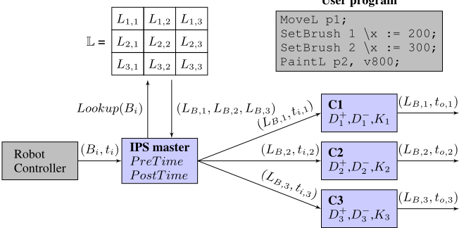
Figure 1 shows an example user program. The instruction MoveL p1 moves the robot to the Cartesian point p1. The two SetBrush instructions tells the robot to apply spray pattern 1 when the robot reaches 200 on the x-plane, and to apply spray pattern 2 when it reaches 300. Both SetBrush instructions tell the IPS to apply a specific behavior when the robot arm is at a given position. The last instruction (PaintL) starts the movement of the robot from the current position p1 to p2 and activates the painting process. The speed is given by the v800 argument, meaning 800 mm/s.
Assuming the path from p1 to p2 results in a movement from x = 0 to x = 500. The robot controller interprets the user program ahead of the actual physical movement of the robot, and can therefore estimate when the robot will be at a specific position. Assuming that the movement starts at time t = 0, the robot can compute that the two SetBrush activations should be triggered at t1 = 250 ms and t2 = 375 ms.
The robot controller now sends the following messages to the IPS master: (B1 = 1↪ t1 = 250)↪ (B2 = 2↪ t2 = 375), which means apply spray pattern 1 at 250 ms, and spray pattern 2 at 375 ms. These messages simply convert position into an absolute global activation time. The messages are sent around 200 ms before the actual activation time. Thus, the IPS may receive the second message before the first spray pattern has been applied, which means that the IPS must handle a queue of scheduled spray patterns.
On receiving a message from the robot controller, the IPS determines the physical outputs associated with the spray pattern number. Many different spray patterns can be generated based on paint type or equipment in use. In the IPS each spray pattern is translated into 3 to 6 different actuator outputs that must be activated at appropriate times.
Figure 1 shows three such actuator outputs (C1, C2, C3). The value of each actuator output for a given spray pattern is resolved using a brush table, L. The IPS master passes these values obtained from L to each actuator output along with its desired activation time, which may be different from the original time received from the robot controller. For additional details, see [Mossige et al., 2014].
Activation of actuator outputs: Since painting involves many slow physical processes, the actuator outputs must compensate for this by computing adjusted activation times to↪j, for each output j, to account for the time it takes the physical process to apply the change. Please see [Mossige et al., 2014] for details.
Physical layout of the IPS: Figure 1 shows the logical connections in an example IPS configuration. In a real-world configuration, each component (IPS master, C1, C2, C3) may be located at different embedded controllers, interconnected through an industrial-grade network. As such, the placement of the different components of the robot depends on the physical process it is responsible for.
3 Testing the IPS
Having a distributed control system such as the IPS mounted on a physical robot makes its validation unnecessarily complex, and past testing practices involved a considerable amount of manual work to set up and collect observations.
Thus, to simplify the testing process, we have developed an automated testing framework for the IPS as an integrated part of ABB's CI environment, where we use CP to generate both the configuration for the IPS, the test sequence, the brush table and the expected actuator outputs. Finally, we execute the test as part of a CI cycle.
In [Fowler and Foemmel, 2006] it is emphasized that a crucial success criteria for a CI deployment is to keep the overall round-trip time as short as possible. That is, the time it takes from a developer has submitted a code change to the source control repository, until feedback on the build and test process is returned. To this end, we have identified a few areas that demand particular attention:
- ÷ Test complexity: In CI, a less accurate but faster test will often be preferred, over a slow but accurate test. In practice, a test must satisfy the so-called good enough criterion, frequently used in industry [Stolberg, 2009].
- ÷ Solving time: Constraint-based optimization is usually a time-consuming task, especially if a global optimum is sought [Marriott and Stuckey, 1998]. Thus, utilizing CP in CI to solve for an optimal test sequence, implies that a time-contracted optimization procedure should be used. This allows precise control over the time needed find a solution, possibly at the expense of solution quality.
- ÷ Execution time: The test execution time depends on the length of the test sequence, i.e., the number of test scenarios. Thus, execution time and the time needed to generate the test sequence must be considered together.
In essence, balancing between the length of a test sequence (its execution time) and the time needed to generate the test sequence (its solving time) represents the appropriate tradeoff for the integration of CP into a CI process.
4 CPModel of the IPS
We now present our CP model for the IPS. Models are usually not meant to reflect the full system behavior [Utting and Legeard, 2007], and as such, we focus on modeling the timing aspects of the IPS in order to build an efficient CP model for generating test scenarios.
Our CP model has C actuator outputs (C = 3 in Figure 1). The decision variables in our model can be divided into three groups: the variables of the input sequence I, the configuration variables C, and the variables of the brush table L. In principle, a solution of the CP model is formed by an instantiation of these variables, in addition to the so-called test oracle O, which is the expected output computed by the system formed by each actuator output and its corresponding time.
We have identified several test scenarios, and three of them are shown in Figure 2. Scenarios overlap and kill brush represent failure conditions, where the IPS is forced into an error state. The objective of these scenarios is to test that the IPS responds correctly, e.g. triggers a safe shutdown, or gives an appropriate error message etc. On the other hand, the normal scenario represents the expected IPS behavior. When solving the CP model, a scenario is given as a test objective to the solver, and the solving process seeks to find an assignment of variables that can drive the execution of the IPS into the desired scenario.
In [Mossige et al., 2014] we detail our approaches to avoid trivial solutions and ensuring diversity in the test input sequence I, the configuration variables C, and the brush table L. The objective of greater diversity is to produce test scenarios with a higher chance of discovering errors in the IPS. Moreover, we ensure that our model mainly use realistic values, to avoid that too many unrealistic scenarios are produced.
4.1 Searching for Optimal Solutions
The purpose of our CP model is to find solutions that has the potential to uncover errors. To this end, finding optimal solutions are the most interesting, because then the test scenarios can be executed faster, and more tests can be executed in the CI process in the same amount of time. As such, we seek to find the input sequence I = ((B1↪ t1)↪ ▷ ▷ ▷ ↪ (Bn↪ tn)) which has the shortest execution time, i.e., where tn is minimized. Clearly, finding the minimum execution time tn is the most desirable, however from a practical perspective, this needs to be balanced against the time, ts, it takes the solver to find this optimal input sequence. That is, the total time used to both find a solution and run the tests is roughly ts + tn.
In [Mossige et al., 2014] we evaluate several search heuristics aimed at finding good enough solutions quickly.
5 Implementation and Exploitation
This section details our implementation of the CP model with SICStus Prolog and its clpfd library [Carlsson et al., 1997], and its exploitation in the CI process at ABB Robotics. However, we first explain the rationale behind our choice of CP over other possible techniques.
5.1 Selection of CP and the CP solver
Our CP model could have been implemented with techniques, such as SAT- or SMT-solving [Moura and Bjørner, 2008], local search techniques for test data generation [McMinn, 2004], or Mixed Integer Programming (MIP) [IBM, 2006]. These were discarded for the following reasons 1 :
- The technique must be able to accommodate the many alternatives in the dynamic configuration of the IPS. CP offers a higher degree of flexibility to handle disjunctive constraint systems, enabling backtracking, reification, and constructive disjunction [Rossi et al., 2006].
- Time-constrained optimization was essential for our industrial use case, in order to satisfy the time requirements of the CI process. SAT- and SMT-solvers are efficient for boolean and theory-based satisfiability problems [Moura and Bjørner, 2008], but they are generally not tuned for optimization problems, e.g., to minimize a cost function in a given contract of time. On the contrary, CP integrates time-aware optimization methods for discrete combinatorial problems.
- As the model is used to predict the expected outputs of the IPS, using exact methods was mandatory. Despite the efficiency of local search techniques for test data generation [McMinn, 2004], the absence of guarantee on the satisfiability of the constraints (e.g., no possible detection of unsatisfiability or no guarantee on the determination of satisfiability for complex constraint sets) was sufficient to discard these techniques.
5.2 Model Implementation
The complete system contains about 2k lines of Prolog code, 300 lines of C code (a DLL interface between Python and SICStus), and about 3k lines of Python code.
The modeling part of the project began in early 2013, and evolved to support testing the complete distributed system of multiple embedded computers running the IPS. Today, the model is used in ABB's CI process and solved daily. It generates test sequences for 11 different IPS configurations. When testing on complete system, we currently run the model on a single physical setup, but we run 10 different configurations of this setup. In summary, the number of activations of physical actuator outputs shows that around 20.000 distinct test scenarios are executed for each CI cycle. That is, each of these test scenarios are executed at least once per day.
1 Note that no general claim is made, just specific claims to illuminate our choice of CP in the case of validating the IPS.

5.3 Execution of the Model
The steps below outline the test execution process.
- Build: Building the IPS software is scheduled to run every night, or a developer can trigger a build manually.
- Upgrade: Upgrade the embedded controllers with the newly built software. A failure aborts the CI cycle.
- Configure: Configuration fetched from the source control repository is loaded onto the IPS. The configuration describes the interconnections of embedded controllers and the properties of this specific paint setup.
- Query and Solve Model: Data retrieved from the IPS is fed into the CP model. This enables us to keep the generated test in sync with changes in the newly built software or changes in the configuration.
- Run Test: Finally, the actual test is executed by applying the generated test sequence, and comparing the actuator outputs with the model generated oracle, O.
6 Lessons Learned
We conclude the paper with some lessons learned from our experience with adopting CP in ABB Robotics' CI process.
6.1 CP for Validation Engineers
As mentioned previously, validating the software for paint robots involves a fair amount of manual, labour-intensive work, which is also error-prone. Therefore, automating parts of this validation process is necessary, and is perceived by validation engineers as a means to strengthen the process.
However, adopting CP also comes with some challenges: (1) Integrating CP into the CI process, including automated builds, software upgrades, test execution, and collecting results. This takes time and requires some maintenance, but is otherwise a relatively simple task. (2) Establishing trust among the validation engineers. This is the most critical issue for adoption, because validation engineers (a) may not be sufficiently trained in CP to change the model without assistance, and (b) may be reluctant to trust a tool whose results that are difficult verify manually. It is also recognized [de la Banda et al., 2013; Francis et al., 2012] as a concern that many optimization problems require expert knowledge.
In order to reduce the risks, we built a Python frontend to our CP model, so as to reduce the complexity exposed to the validation engineers. We also organized basic training in CP with simple and understandable examples, in order to facilitate adoption. We do not claim that these actions form a recipe for adopting CP in general, but we observe that it worked well in the context of ABB Robotics IPS validation.
6.2 Actual Defects Found with the CPModel
After the CP model was put into production at ABB Robotics, we immediately found two new unknown defects related to timing aspects in the IPS. However, these defects were classified as non-critical, as they represent very unlikely scenarios. Upon further examination, we found that these defects had been present in the IPS for several years without any significant consequences, and that they were found by the CP model due to diversity in the selection of test sequences. These defects have been corrected and their corresponding test sequences have been added to our non-regression test suite.
For validating the CP model, we also reintroduced five old, historical, defects into the source control repository. These defects were known by the validation engineers to be extremely hard to find. After a round of experiments, the CP model produced test sequences that spotted all five defects. This was considered as a strong justification for the continued use of the CP model in production.
6.3 Return on Investment with the use of CP
Computing the return on investment for the use of CP for ABB Robotics' IPS validation is difficult. Possibly, one can measure the number of defects found with and without the CP model during the validation of a new IPS release. It is also possible to compare the human effort required in both cases. However, another important factor is the increased confidence of the engineers to the validation process, which is a factor that is very difficult to quantify. After the introduction of the CP model in production, we observed a much higher confidence among the engineers and their appetite to perform necessary code re-factoring is now higher. They are more willing to make critical, but needed, changes in the software and they rely on the test framework to detect undesired side-effects. If a side-effect is discovered, they can simply roll back the change.
In the long term, we expect to see the benefits of using CP being recognized as a way to increase the general quality of the testing process, since necessary re-factoring will be performed before the technical depth grows beyond control.
@inproceedings{ijcai2016p630,
  title     = {Generating Tests for Robotized Painting Using Constraint Programming},
  author    = {Mossige, Morten and Gotlieb, Arnaud and Meling, Hein},
  booktitle = {Proceedings of the Twenty-Fifth International Joint Conference on
               Artificial Intelligence, {IJCAI-16}},
  publisher = {AAAI Press / International Joint Conferences on Artificial Intelligence},
  editor    = {Subbarao Kambhampati},
  pages     = {4200--4203},
  year      = {2016},
  month     = {7},
  url       = {https://ijcai.org/proceedings/2016/630},
}
TY - CPAPER TI - Generating Tests for Robotized Painting Using Constraint Programming AU - Mossige, Morten AU - Gotlieb, Arnaud AU - Meling, Hein T2 - Proceedings of the Twenty-Fifth International Joint Conference on Artificial Intelligence, IJCAI-16 PB - AAAI Press / International Joint Conferences on Artificial Intelligence PY - 2016 SP - 4200 EP - 4203 UR - https://ijcai.org/proceedings/2016/630 ER -Copied
Machine-readable versions of this paper, for tools and AI agents:





