Visual Planning: A Practical Approach to Automated Presentation Design
Proceedings of the Sixteenth International Joint Conference on Artificial Intelligence. Knowledge-based Applications. Pages 634-640.
© 1999 International Joint Conferences on Artificial Intelligence
Abstract
Based on a set of design principles, automated visu?l ~resentation systems promise to simplify an applicatiOn programmer's design tasks by automatically constructing appropriate visual explanations for diff~r~nt information. However, these automated pre~entatwn systems must be equipped with a powerful mference approach to suit practical applications. Here, we present a planning-based, practical inference approach that can design a series of connected visual presentations in interactive environments. Our emphasis here is on a set of important visual planning features and how they facilitate visual design. This s.et of fea~ures includes a knowledge-rich representatiOn of vtsual planning variables and constraints, a novel object-decomposition model that can be used with. action decomposition to simplify the visual synthe~ts process, and practical temporal and spatial reasonmg capabilities to facilitate coherent visual design and presentation. In addition, we have implemented our visual planning approach in a visual planner called PREVISE, as part of our automated presentation ~estbed system. A set of examples is also given to tl~ustrate the necessity and utility of our visual planmng approach.
- Allen, J. (1983). Maintaining knowledge about temporal in- tervals. Communications of the ACM, 26(11):832-843.
- Andre, E. and Rist, T. ( 1993). The design of illustrated docu- ments as a planning task. In Maybury, M., editor, Intelli- gent Multimedia Interfaces, chapter 4, pages 94-116. AAAI Press!The MIT Press, Menlo Park, CA.
- Andre, E. and Rist, T. (1996). Coping with temporal con- straints in multimedia presentation planning. In Proc. AAAI '96. AAAI.
- Bares, W. and Lester, J. (1997). Realtime generation of cus- tomized 3d animated explanations for knowledge-based learning environments. In Proc. AAAI '97, pages 347- 354.
- Borning, A., Freeman-Benson, B., and Wilson, M . (1992). Constraint hierarchies. List and Symbolic Computation, 5(3 ):223-270.
- Currie, K. and Tate, A. ( 1991 ). 0-plan: The open planning ar- chitecture. Artificial Intelligence, 51(1):49-86.
- Freeman-Benson, B. (1993). Converting an exising user in- terface to use constraints. In Proc. UIST '93, pages 207- 215. ACM.
- Gleicher, M . (1994). A Differential Approach to Graphical Interaction. PhD thesis, School of Computer Science, Carnegie Mellon University, Pittsburgh, PA 15213- 3891.
- JSC-25012 (1993). CLIPS Reference Manual. Software Technology Branch, Lyndon B. Johnson Space Center. CLIPS Version 6.0, JSC-25012.
- Karp, P. and Feiner, S. (1993). Automated presentation plan- ning of animation using task decomposition with heuris- tic reasoning. In Proceedings of Graphics Interface '93, pages 118-127.
- Kautz, H. (1991). MATS (Metric/Allen Time System) Docu- mentation. AT&T Bell Laboratories.
- KRSL (1993). Knowledge Representation Specification Lan- guage Reference Manual. DARPA/Rome Laboratory Planning and Scheduling Initiative Knowledge Repre- sentation and Architecture Issue Working Group. Ver- sion 2.0.2.
- Seligmann, D. and Feiner, S. (1991). Automated generation of intent-based 3D illustrations. Computer Graphics, 25(4):123-132.
- Tate, A. (1996). Representing plans as a set of constraints: the I-N-OV A model. In Proc. AlPS '96, Edinburgh, UK. AAAI Press.
- Tate, A., Drabble, B., and Kirby, R. (1994 ). O-plan2: An open architecture for command, planning and control. In
- Fox, M. and Zweben, M., editors, Intelligent Scheduling.
- Morgan Kaufmann.
- Wernecke, J. (1994). The Inventor Mentor: Programming Object-Oriented 3D graphics with Open Inventor. Addi- son Wesley, Reading, MA.
- Wilkins, D. (1988). Practical Planning: Extending Classical AI Paradigm. Morgan Kaufmann, San Mateo, CA.
- Wilkins, D. and Myers, K. (1995). A common knowledge representation for plan generation and reactive execu- tion. J. of Logic and Computation, 5:731-761.
- Wilkins, D., Myers, K., Lowrance, J., and Wesley, L. (1994). Planning and reacting in uncertain and dynamic environ- ments. Journal of Experimental and Theoretical AI, 6:197-227.
- Young, R., Pollack, M., and Moore, J. (1994). Decomposi- tion and causality in partial-order planning. In 2nd Int. Conf on AI Planning Systems: A/PS-94, pages 188-193.
- Zhou, M. (1998). Automated Generation of Visual Discourse. PhD thesis, Columbia University, New York, NY.
- Zhou, M. and Feiner, S. (1997). Top-down hierarchical plan- ning of coherent visual discourse. In Proc. lUI '97, pages 129-136, Orlando, FL.
- Zhou, M. and Feiner, S. (1998). Visual task characterization for automated visual discourse synthesis. In Proc. CHI '98, pages 292-299, Los Angeles, CA. ACM.
References were extracted automatically from the PDF and may contain errors.
Full text extracted automatically from the PDF; figures, tables and equations may differ. The PDF is the version of record.
1 Introduction
.Automated visual presentation systems rely on a power f~l mference engine to generate desired presentations effi Ciently. In this paper, we present a practical inference ~~thod th~t uses a planning approach to infer visual designs m mteractive environments.
A visual design ultimately appears in the form of a visual dis~ourse th~t consists of sequences of temporally ordered visual actiOns [Zhou, 1998]. Visual actions are encoded visual techniques, which may render a collection of graphics objects on the screen (e.g., action Display), or ani mate a graphical transformation (e.g., Enlarge). Since such a pattern is re~iniscent of the result produced by AI planning, we model vtsual design as a planning problem. In particular, the communicative goals are accomplished as planning goals, visual design guidelines are maintained as planning constraints, and visual actions are employed as planning operators to construct a visual plan (a visual discourse).
t This work was conducted at Columbia University, as part of the author's Ph.D. thesis in the Dept. of Computer Science.
The co~e of our visual planning is a least-commitment, top-down hierarchical decomposition partial-order planning approach [Young et al., 1994]. Combined with a set of visual design heuristics [Zhou and Feiner, 1997], this approach helps minimize costly redesign, eases knowledge encoding by reusing visual actions, and ensures global and local design coherency. Furthermore, we have equipped the core appr?ach with a~ ad?itional set of fe.atures. Specifically, we provtde a versatile vtsual planning representation formalism t~ ex~ress ?nd man~ge progressively refined visual plans. To stmplify vtsual obJect synthesis and knowledge manage ment, we explicitly address object decomposition. We also augm~~t.visual pla~nin~ with temporal and spatial reasoning capabilities to mamtam temporal and spatial constraints [Allen, 1983; Freeman-Benson, 1993]. In addition, we have implemented our approach in a visual planner called PREVISE (Planning in REactive VISual Environments), which is part of an automated presentation testbed system.
. In the rest of the paper, we focus on illustrating these Important features of our visual planning approach. But first we briefly de~cribe several related works, followed by an example that IS planned by PREVISE to illustrate the visual plann~ng problem. We then describe four important visual planmng features and explain how they facilitate automated visual design. Finally, we present our conclusions and indi cate some future research directions in visual planning.
2 Related Work
. While most automated presentation systems employ SI~ple search-based approaches (e.g., [Seligmann and Femer, 1991]) ·. a few have used planning approaches (e.g., [Andre and Rist, 1993; Karp and Feiner, 1993; Bares and Lester, 1997]). However, systems using planning approaches either deal with static presentations [Andre and Rist, 1993] or. focus on planning camera movements [Karp and Femer, 1993; Bares and Lester, 1997]. Furthermore, these system~ usually ha~dle premade graphics objects at a high l~~el Without worrymg about low-level visual object compo SitiOn (e.g., composing a visual object using basic visual elements such as color and shape).
Aiming to create a coherent visual discourse from scratch, our work involves both visual composition and transformation. Thus, we have designed a more sophisticated visual planning approach. This approach, implemented in PREVISE, is based in part on two planning systems: DPOCL [Young et al., 1994] and SIPE [Wilkins, 1988; Wilkins et al., 1994]. DPOCL is the first system to explicitly address top-down action decomposition with partial-order planning, while SIPE can plan in a reactive environment. From DPOCL, PREVISE inherits the top-down action-decomposition strategy and amplifies it to accommodate object-decomposition; and from SIPE, PREVISE partly adopts its plan and action repre sentation formalisms, but further expands them to allow more knowledge rich representations.
3 Example
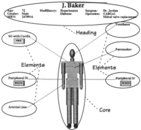
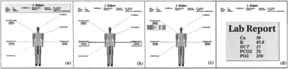
We use one complex example, shown in Figure 1 and Figure 2, to illustrate the characteristics of visual planning. In this example, our task is to present a patient's information to a nurse after the patient's coronary artery bypass graft (CABO) operation. As the final presentation contains coordi nated text, speech, and graphics, here we only concentrate on how the graphics presentations are planned.
:3. Attach Bottom
([lv2], (iv2].contente)
4. AllgnleftOffeet
(1ta17, (iv2], (iv2].contente)
Figure 3. Present patient overview to nurse (annotated)
In this task, PREVISE must accomplish two goals. The first goal is to create an overview of patient information, and the second is to elaborate the patient information details based on the created overview. To achieve the first goal, PRE VISE plans to construct a structure diagram (Figure 1) that organizes various information (e.g., IV lines) around a core component (e.g., represented by the patient's body). This decision is made based on the fact that nurses prefer to see all information arranged relative to the patient's body. In a top-down design manner, PREVISE first creates an "empty" structure diagram. This empty diagram is then defined through its individual components by recursively partition ing and encoding the patient information into different groups. As shown in Figure 1, the patient's demographics information, including name, age, and gender as a group, is encoded as the heading of the diagram; the patient's physical body serves as the core, and the rest of the information is arranged around the core as diagram elements. To express the partial designs and their refinement, PREVISE uses vari ables and constraints to represent the progressively refined diagram at different levels of detail. In addition, PREVISE must formulate and satisfy a set of spatial constraints to determine the sizes and locations of various diagram compo nents (Figure 3).
/
Age:
7l J.Baker MHHktory: Hyper1en.doa Snrgeuu: Dr. Jordan
Gender: Made DU.Mta Opention: CABGd
Mll.'f: 1478916
Mitral valve npl11cemeat
1. Allgnleft((eg], (iv1], (art1])
.1 Allgnleft([eg].name, (iv1].name, "r"'·""rn.'
1.2 Align left
/
Arterial
([eg].contente,
(iv1].contente)
To accomplish the second goal, PREVISE plans a series of visual actions to allow certain information to be reinforced or revealed based on the overview. Figure 2(a-b) are created to reinforce the patient's demographics information and JVs using the visual action Highlight, while Figure 2(c-d) are planned to reveal the drip (intravenously administered drug) and lab report details. To introduce new information (e.g., drip details) into an existing display, PREVISE reasons about the spatial arrangement of existing objects and the placement of new objects. Finally, PREVISE ensures that all visual actions are temporally coordinated to produce a coherent presentation; for example, the highlighting on the demo graphics in Figure 2(a) should be turned off before the JVs are highlighted in Figure 2(b ).
4 Visual Planning
In this section, we concentrate on illustrating four dis tinct visual planning features and explain how they aid visual design. To facilitate a flexible and efficient planning environ ment, we first present a knowledge-rich and object-oriented representation formalism for visual planning. Using this rep resentation, we describe how to explicitly employ object decomposition with action decomposition to simplify visual synthesis. To create both temporally and spatially coherent presentations, we address temporal and spatial reasoning issues in visual planning.
4.1 Visual Planning Representation Formalism
Using a top-down design strategy, a visual planning pro cess must deal with partially specified visual plans at multi ple levels of abstraction. To capture and manage these complex partial plans, we have developed a knowledge-rich object-oriented representation formalism based on previous work (e.g., [KRSL, 1993; Wilkins and Myers, 1995; Tate, 1996]). Specifically, our representation formalism per mits the efficient usage of complex planning variables and constraints, and allows a rich expression of planning opera tors (visual actions). For illustration purpose, all examples given below are presented in a simplified frame-like repre sentation formalism, where brackets [ ] are added around symbols to indicate object instances.
Planning Variables and Constraints
Unlike any of other planning variables used in complex planning systems (e.g., [Currie and Tate, 1991; Wilkins and Myers, 1995]), visual planning variables are first declared in s-expressions, and are then created and managed as object instances. Figure 4 shows how a PREVISE variable may be declared with a symbolic id, a specific binding type, and a set of constraints. The symbolic id can either be in a form of ?x or $?y to distinguish a single valued variable (x) from a multi valued one (y). When created, a variable instance is assigned a binding property to indicate how it should be . managed [KRSL, 1993]. For example, a REQUIRED variable must be bound during planning, while an OPTIONAL variable may not be bound at all through the entire planning process. A vari able may be created with or without a binding, a set of binding Candidates, or even a defaultBinding. Moreover, this variable instance may refer to another variable instance or be referred by others during planning.
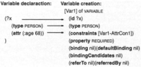
Having a separate variable declaration and creation eases both knowledge encoding and planning. In particular, variables are declared in s-expressions during knowledge encoding without dealing with the details of object creation and management. On the other hand, variables are easily handled as objects in planning without repeatedly processing complex symbolic representations. In addition, our visual planner can rely on various variable attributes described above, including variable property and references, to effi ciently decide when and how to update variables. For exam ple, using the variable reference information, if a variable binding is updated, so are all the variables that refer to this one.
It is worth noting that we also allow a special type of dynamic variables in visual planning. During planning, these variables may be continuously updated by a numerical con straint solver called STM [Gleicher, 1994]. Hence we refer to them as to STM-VAR. Unlike dynamic variables in other sys tems (e.g., [Wilkins and Myers, 1995]), a STM-VAR is more flexible in use (e.g., we do not need to explicitly specify its rebinding), and more efficient in representation. For exam ple, a STM-VAR, used to represent a 3D bounding box, can be used to capture the changing geometry of a 3D object through five other variables (center, objCenter, width, height, and depth).
In visual planning, a PREVISE variable is usually accom panied by a set of constraints, which are also handled in the similar fashion as variables. In other words, visual planning constraints are specified initially in s-expressions, and are instantiated and managed as object instances during plan ning. To facilitate constraint management, we classify con straints based on their origination (e.g., META or SUFFICIENCY constraints in [Tate, 1996]) and duration (e.g., ONE-TIME or ALWAYS constraints in [KRSL, 1993]). Moreover, we assign constraints with strength (e.g., REQUIRED or PREFERRED) and type (ATOMIC or ABSTRACT) to organize them into a hierarchy [Berning et al., 1992]. This constraint hierarchy not only allows object relationships to be expressed at multiple levels of abstraction, but also allows for a more efficient constraint management (see Sections 4.3 and 4.4).
Visual Action
In visual planning, a visual action captures both the properties of a planning operator and a visual technique. As a visual technique, a visual action can be a formational action that creates a visual object from scratch (Figure 5a),
DesignTableChart (is-a FORMATION-ACTION) (a) (operands (?x (type DOMAIN-OBJECT) (?t (type TABLE-CHART))) (local Parameters (?heading (type VISUAL-UNITY) (property OPTIONAL)) · . · ) (purposes ENCODE I TABULATE) (effects (effect1 (Encode ?x ?t)) (effect2 (Table ?t))) .. . Move (is-a TRANSFORMATION-ACTION) (b) (operands (?v (type VISUAL-OBJECT))) (locaiParameters (?src (type VECTOR)) (?dest (type VECTOR))) (purposes TRANSFORM I REPOSITION) (preconditions (cond1 (Existing ?v)) (cond2 (At ?v ?src)) ... ) (effects (effect1 (At ?v ?destination))) . . .or a transformational action that modifies an existing visual object (Figure 5b). Since formational actions do not actually perform graphics rendering, they are not included in the final plan but their results might be. For example, the formational action, DesignTableChart, itself does not appear in the final plan, but its result-the created table chart may appear in the final plan with a Display action.
We also assign purposes to each visual action to summa rize its functions at different levels of abstraction. For exam ple, the purposes specified in the action Move indicate that it can be u.sed to transform a visual object in general, specifi cally to reposition a visual object (Figure 5b). In addition, we use the purposes to index visual actions and create parti tioned search space to reduce search time. This helps us cope with a large number of visual actions efficiently during plan ning. For example, when searching for a proper visual action to accomplish a transformation task, PREVISE only searches among the visual actions that have Transform as one of their purposes. Otherwise, PREVISE must examine the postcondi tions of all visual actions to find a match.
Much like a SIPE operator [Wilkins and Myers, 1995], visual action arguments are represented as variables with constraints on their binding types or properties. For example, the variable ?heading is optionally bound to a particular visual object (Figure 5a). But unlike SIPE, visual action argu ments are separated into two groups: operands and local parameters. Whereas operands provide the uniform interface to access an action, local parameters describe a set of attributes specific to that action. In particular, formational actions use operands to specify their input and output (e.g., ?x is the input and ?t is the output of DesignTableChart in Figure 5a), and transformational actions use operands to indi cate their recipients (e.g., ?v of Move in Figure 5b). On the other hand, both formational and transformational actions use locaiParameters to record all needed parameters to com plete the action (e.g., ?heading of DesignTableChart, 'Or ?dest of Move) . Separating the operands from local parameters simpli fies the action instantiation process since PREVISE needs to consider only the operands during this stage. This allows the instantiations of local parameters to be delayed; for example, PREVISE is not concerned with local parameters, such as ?dest (the destination of the movement) in Move, at a high level of the design.
To simplify the planning process, plan goals in PREVISE are also specified similar to actions. For example, the com municative goal to create a summary of patient information, achieved in Figure 1, is notated as a rhetorical act, Summa rize<?patient-info>. Based on the domain-specific nurse prefer ence rule, this general act is then refined to a visual goal Structure<?patient-info> that requires all information to be structured in a specific way. This visual goal is in fact an abstract visual act, which can be accomplished by other visual actions (e.g., action DesignStructureDiagram) [Zhou and Feiner, 1998].
4.2 Object Decomposition
As a planning operator, a visual action may be a primi tive action that can be directly executed by a plan agent, or a composite action that contains a set of partially specified subplans and must be replaced by the subplans during plan ning. PREVISE usually uses composite actions to sketch a design at a high level, and refines the vague parts of the design into more detailed ones using primitive visual actions. During such a design refinement, action and object decom position may both be required. For example, a DesignTable Chart action may be decomposed into a set of subactions that define individual table components. In the meantime, the input (the data ?x) used to produce the table chart must also be decomposed into smaller units that can be used by the subactions. Although in certain cases object decomposition could be implicitly handled by action decomposition, entan gled action and object decomposition makes visual planning extremely difficult (e.g., a data object may be decomposed into different subparts under different situations). Thus, we explicitly introduce object decomposition in visual planning
DeslgnTableChart (is-a FORMATION·ACTION) (actionDecomSchemata [actD1] . . . ) (objDecomSehemata [objD1] (objD2) [obj03] .. . ) ( objDecompPreferencea (preference1 (:condition (is-itemize ?x)) (:prefer [obj01])) (preference2 (:condition (is-overview ?x)) (:prefer [objD2])) (always [obj03])) (act01) of ACT-DECOMPOSITION-SCHEMA (subactlons (:loop ?I (:range 1 ?n)(:update (bind ?i (+ 1 ?i))) (Subaction<?i> (:expr (DesignVisRep ?x<?i> ?t<?i>))))) (obj01) of OBJECT-DECOMPOSITION-SCHEMA (objld ?x) (numParts ?n = :(get-numOflndividual)) (subParts (:loop ?i (:range 1 ?n) ?x<?i> = :(get-indivi(fual ?i))) (ob)02) of OBJECT-DECOMPOSITION-SCHEMA (ob)ld ?x) (numParts ?n = :(get-numOfGroup)) (subParts (:loop ?i (:range 1 ?n) ?x<?i> = :(get-group ?i))) (ob)03) of OBJECT-DECOMPOSITION-SCHEMA (ob)ld ?t) (subParts (:loop ?I (:range 1 ?n) IF (is-identifier ?x<?i>)) THEN (put-heading ?t ?t<?i>) ELSE (put-cells ?t ?t<?i>))) Figure 6. A visual action and its decomposition schematausing a set of object decomposition schemata.
An object decomposition schema uses objectld to identify the object to be decomposed, subParts to specify a set of components that the object is decomposed to, and numParts to indicate the total number of subparts (Figure 6). Unlike action decomposition where only one decomposition schema can be used at one time, more than one object decomposition schemata may be applied simultaneously. For example, PRE VISE may use [objD1] in Figure 6 to decompose the data ?x, but always uses [objD3] to determine the structural relation ships between the table chart itself (?t) and its components (?t<?i> ). To determine which and when an object decomposi tion schema should be used, PREVISE uses preference con straints stored in objDecompPreferences. Moreover, variables are used extensively in decomposition schemata to express partial plans and objects, or to represent unknown situations (e.g., ?n).
In general, two types of object decomposition occur in visual planning. In the first case, a completely specified object (e.g., a piece of data to be conveyed) needs to be decomposed into smaller units to be manipulated (e.g., decomposition schemata [objD1] and [objD2] in Figure 6). In the second case, a partially specified object (e.g., a visual object to be defined) must be decomposed into subparts so it can be refined through the subparts (e.g., [objD3J). Both types of object decomposition promote a simpler and more general knowledge encoding and management.
Using the first type of object decomposition, we can eas ily handle the uncertainty involved in action decomposition. For example, during knowledge encoding, the number of subactions in [actD1] may be unknown, depending on how the data (?x) will be processed in the actual planning process. In this case, before instantiating subactions in [actD1], PREVISE can establish the needed variables (e.g., ?n) by selecting an object decomposition schema (e.g., [objD1J) based on objDe compPreferences (e.g., preference1 ). This approach allows a simple and general representation of action decomposition, which only needs to specify the unknowns using variables (e.g., ?n in [actD1J).
The second type of object decomposition also helps gen eralize and simplify action decomposition. Without the object decomposition schema [objD3], for example, we must replace the general action DesignVisRep with more specific subactions, such as DesignTableHeading and DesignTableCell, to define various table constituents. In addition, we must con sider all the possible combinations of these specific subac tions to construct different subplans (e.g., a subplan may require a subaction DesignTableHeading, but another may not). This not only requires a number of different actions to be defined, but also increases the complexity of knowledge management. Considering the case of defining a new action DesignBarChart, we need to introduce a set of new actions (e.g., DesignAxes and DesignBar) for various bar chart constit uents. We must also ensure that each subaction is supplied with the proper data components to guarantee the design cor rectness. For example, only quantitative data components may be involved in the subaction DesignBar.
Therefore, separating the object decomposition from the action decomposition allows simpler and more general representations for action decomposition. More importantly, these simpler and more general representations improve PRE VISE's applicability by easing its tasks of knowledge encod ing and management.
4.3 Temporal Reasoning
During a visual presentation, visual actions can occur concurrently or over extended time intervals. To create a temporally coherent visual presentation, we have integrated temporal reasoning into PREVISE to ensure that visual actions are temporally coordinated. Compared to other systems (e.g., [Tate et al., 1994; Wilkins and Myers, 1995; Andre and Rist, 1996]), PREVISE uses multilevel topological and metric time constraints to describe actions at a finer granularity dur ing planning generation. It also employs a novel scheduler to ensure that all temporal constraints are met during planning execution.
Temporal Constraint Specification
PREVISE deals with two types of temporal constraints: Inter-action constraints specify temporal relations between two visual actions, and intra-action constraints describe tem poral relations within a visual action.
Inter-Action Temporal Constraints. PREVISE uses topo logical constraints to represent · temporal relationships between two visual actions qualitatively. These constraints can be represented as either time-point or time-interval con straints. In general, PREVISE allows three types of time-point constraints: BeforeAt, AfterAt, and EquatAt; and permits time interval constraints, containing any subset of the thirteen basic temporal relations defined in [Allen, 1983]. When described in time-point constraints, visual actions may be considered instantaneous. In contrast, visual actions have distinct starting and finishing times when specified using time-interval constraints.
Allowing both time-point and time-interval constraints not only enables PREVISE to represent different temporal relationships accurately, but also helps to handle temporal constraints efficiently by exploiting a multilevel constraint representation. Usually, we can use concise time-point con straints to specify incomplete temporal relations at a high level, and employ time-interval constraints to express more refined temporal relationships at a low level. For example, PREVISE can use a simple time-point constraint to assert that action A must start before B at a high level, without knowing their finishing times:
(BeforeAt A B)
Later, this constraint can be refined using one of the three more specific time-interval constraints based on their finish ing times:
1. A finishes before B: (Overlap A B)
2. A finishes after B: (Contain A B)
3. A and B finishes at the same time: (Finished By A B)
This multilevel temporal constraint representation helps avoid computationally complex temporal reasoning at a high level, hence improves planning efficiency.
Intra-Action Temporal Constraints. In addition to tem poral constraints between visual actions, we also describe temporal relationships within an action. Unlike inter-action temporal relationships, these relations are described quanti tatively using metric time constraints (usually in seconds).
In general, a PREVISE action has a startTime and an end Time to regulate when and how long the desired visual effects should appear on the screen. But we add subtime intervals in a transformational action to describe its animation subacts. In particular, animOnDuration controls the time taken to turn on the desired visual effects (e.g., gradually changing the color of an object to highlight it), holdingDuration specifies how long the current effect should remain on the screen (e.g., holding the highlighting effect), and animOffDuration limits the time taken to reverse the visual transformation (e.g., turn ing off the highlighting). Using these subintervals, we can describe and control a finer-grained visual action and its exe cution. Moreover, we can specify an animation with its reverse without explicitly introducing a set of undo actions (e.g., unhighlight).
To facilitate temporal media coordination (e.g., coordi nating a graphics animation with speech) in a multimedia presentation, we also allow more flexible time-window con straints. For example, we may specify that a Highlight action needs a minimum of 1s or maximum of 2s to turn on the highlight, and another 3s to 4s to hold the highlighting. To coordinate the highlighting with speech, a media coordinator can use the time window to compute a time interval accept able for both graphics and speech.
Temporal Constraint Satisfaction
We deal with temporal constraints in both plan genera tion and execution. In plan generation, we use a simple con straint solver to process qualitative time constraints based on transitive closures. Conversely, we use a constraint solver based on Metric/Allen Time System (MATS) [Kautz, 1991] to process quantitative temporal constraints.
Execution Scheduler. In plan execution, we have imple mented a time queue to schedule visual actions. All visual actions are first entered in the time queue by their starting times. The scheduler then uses a global alarm clock to invoke actions when their starting times are reached. A local timer is also maintained within each visual action to signal its termination when its finishing time approaches.
This approach works fine until this problem arises: Two closely scheduled actions (e.g., actions A and Bin Figure 7a) may overlap as the scheduler cannot guarantee a full stop in previous action (e.g., A) when its local timer expires. This is because the local timer does not account for the time spent for executing various implicit finishing acts. For example, action A may call an instantaneous undo act (animOffDuration is o.os) when its local timer expires. Thus, there is no guaran tee that A's undo act will be finished before B starts.
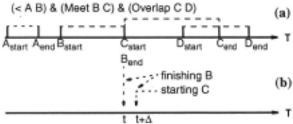
To fix this problem, each action is required to signal the scheduler when it is truly finished. In addition, we insert a dummy finishing act for each action in the time queue by its finishing time to ensure that the global clock be stopped if the previous action is not finished. As shown in Figure 7(a), when the global clock reaches the dummy act Aend· it would not be advanced to action Bstart until it receives /lis finishing signal.
The above approach only fixes half of our problem: it works for actions scheduled one after another (e.g., A and B in Figure 7a), but not for actions scheduled right next to each other (e.g., B and C). In this case, the plan agent is expected to execute two tasks simultaneously: finishing the previous action (B) and starting a new action (C). Since it is physically impossible for uniprocessor machines to process two tasks at the same time, the tasks will be executed in a nondeterminis tic order. This may result in undesirable visual effects. Sup pose B and C are both highlighting actions, and B must finish by removing its highlight before C starts to put on a new highlight. Because of the nondeterministic execution order, C might be started before B finishes to cause an undesired visual effect: two objects highlighted at the same time instead of in sequence.
To ensure desired visual effects, we add sub-order tem poral constraints to serialize simultaneous actions using heu ristics. For example, one heuristic rule in PREVISE asserts that all dummy finishing acts precede any other action scheduled at the same time. In the above example, the plan agent will process Bend before Cstart· as if the time point t is expanded into a time interval [t, t+~J (Figure 7b). This ensures that all objects in action B are unhighlighted before any new object is highlighted in action C.
4.4 Spatial Reasoning
PREVISE performs spatial reasoning in two situations. In spatial composition, PREVISE regulates the size and place ment of visual objects to ensure a valid visual composition. In spatial transformation, PREVISE controls the spatial modi fication of existing visual objects and the integration of new visual objects to maintain a coherent visual transformation.
Spatial Composition
A visual composition is considered valid if all syntactic constraints are satisfied during visual object synthesis [Zhou, 1998]. Among these syntactic constraints, some regu late spatial relationships between visual objects. Figure 3 is annotated to show a set of spatial constraints that must be satisfied in a structure diagram. Moreover, these constraints are specified at different levels of abstraction to capture multi-level spatial relationships. For example, constraint 1 is an abstract spatial constraint, defined at a high level to describe vague spatial relationships between complex visual objects. In contrast, constraints 1.1 and 1.2 express more concrete visual relationships. To be evaluated, an abstract constraint (e.g., constraint 1), must be replaced by a set of more concrete constraints (e.g., constraints 1.1 and 1.2). One distinct advantage of using abstract constraints is to achieve planning efficiency by postponing overwhelming details involved in lower level constraints to a later time.
By evaluating a set of constraints, PREVISE can deter mine the size and placement of visual objects involved. For example, the locations or sizes of various texts in Figure 3 can be determined. In PREVISE, we model spatial constraints using mathematical equations and inequalities, which are eventually solved by STM using a numerical optimization method. Since the optimization method requires a set of proper initial values, we must supply these values for STM to start with. For example, we need to supply the proper initial values for ?line-length and ?tab in constraints 2 and 4 (Figure 3). Currently, these values are obtained based on empirical analyses of many existing graphical representa tions (e.g., hand-made or machine-made structure diagrams). For example, to best illustrate the spatial ratio between the patient body and the lines, we have learned that the length of various lines in the picture is usually at least 113 of the diag onallength of the body's bounding box.
Spatial Transformation
In addition to ensuring a valid visual composition, PRE. ., VISE also uses spatial constraints to control the integration of new information into an existing presentation. In one approach, PREVISE directly adds the new information to the existing scene as visual extensions of existing objects. For example, to reveal drip details (Figure 2c), PREVISE directly adds a pull-down menu as an extension of the drip button in the overview (Figure 1). To determine the size and the place ment of new objects (e.g., the pull-down menu) in relation to the existing objects (e.g., the button), PREVISE reasons about the spatial geometry of the existing scene, including the objects' size, orientation, and topology, by issuing queries. It then formulates constraints based on design heuristics. In our case, based on the current geometry of the drips button, PRE VISE formulates spatial constraints to regulate the size and position of the added pull-down menu.
To avoid unnecessary spatial rearrangement, we also assert a set of spatial constraints in advance to prepare for potential visual changes. For example, a button is usually expected to bring up a pull-down menu when pressed. There fore, when a button is created, a spatial constraint is asserted to ensure that there is enough room reserved below the but ton for placing a pull-down menu (e.g., the space below the drips button in Figure 3).
In general, directly adding new objects to the existing scene is relatively simple since PREVISE deals with a con fined space with rigid spatial constraints (e.g., placing a pull down menu near a button). However, in many cases, PREVISE may need to modify the existing scene dramatically for inte grating new information. In this case, PREVISE must deter mine how to make spatial changes for the new objects. For example, to produce Figure 2(d), PREVISE decides to keep the table chart at the top (e.g., name, age, and gender) of Figure 2(c) to provide the necessary context information, while replaces the rest of representation with the lab report.
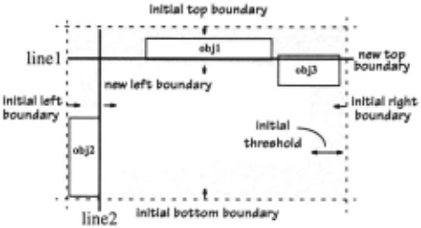
PREVISE currently deals with relatively simple space management cases. Our approach assumes that all existing visual objects will be replaced except the objects that must be kept to provide necessary background or context informa tion. Once PREVISE determines what to keep or to remove, it will plan the size and the placement of the new objects (e.g., the table chart for lab report) using an iterative-adjustment algorithm. To utilize space efficiently and produce a bal anced layout, the algorithm assumes that the kept objects usually reside in the shaded area to leave the middle area for the new objects (Figure 8).
The shaded areas are initially defined by a set of thresh old values to guarantee that at least 2/3 of the display area in the middle be reserved for the new. visual objects. The algo rithm then iteratively computes the bounding box for each object kept in the scene and determines the region containing this object. If the object falls in only one of the eight shaded regions (e.g., obj1 and obj2 in Figure 8), the algorithm adjusts the current boundaries by pushing them toward the center to define unoccupied space. For example, the initial top bound ary is pushed down into line 1, and the initial left boundary becomes line 2 in Figure 8. If the object does not completely fall in any of the eight regions (e.g., obj3) and the threshold values are adjustable, the algorithm recursively increases the current threshold values to recompute new boundaries. If the threshold values are not adjustable, the current existing objects may be modified to create enough room for new objects. Eventually, the algorithm returns four boundaries to define the dimension and position of the area for placing the new objects.
5 Implementation
PREVISE is implemented using both CLIPS [JSC25012, 1993] and C++, currently running on SGis and PCs under Windows NT. The rendering component is written in C++ and Open Inventor, an object-oriented 3D interactive graphics toolkit [Wernecke, 1994]. On a SGI Indigo 2 with a 250 MHz R4400 processor, it takes about 25 seconds to plan the overview of patient record shown in Figure 1, and about 45 seconds to plan the entire detail view of patient record, partly shown in Figure 2.
6 Conclusions & Future Work
In this paper, we have presented a practical visual plan ning approach to automated visual presentation design. In particular, we model visual actions as planning operators, and visual design principles as planning constraints. On top of our core top-down hierarchical decomposition partial order planning approach, we add a set of visual planning fea tures. These features include a powerful visual planning rep resentation, an explicit object decomposition method, and temporal and spatial reasoning capabilities. Moreover, this approach is implemented in a planner, ?REVISE, as part of our automated visual presentation testbed system.
Currently, we are working in two areas to improve the visual planning approach. To allow user interaction during planning generation and execution, we are planning to incor porate reactive planning strategies [Wilkins et al., 1994]. For example, users may suggest changes to the design decisions made by ?REVISE, or interactively alter the course of the exe cution to selectively view the presentation (e.g., executing visual actions out of sequence). Thus, our current approach must be extended to recognize the inadequacy of a current plan, and correct it to meet the new conditions.
To perform spatial analysis and management for more complicated situations, we would also like to enhance the spatial reasoning capability. For example, developing a gen eral and efficient algorithm to query the spatial density of a scene so we can place new objects on the location where the spatial density is low to avoid possible object occlusions.
Acknowledgments
I would like to thank my thesis advisor, Professor Steven Feiner, for his constant support on this work. I would also like to thank Rahamad Dawood for implementing the sched uler, Blaine Bell for porting the entire system to PCs, and Bill Yoshimi, Keith Houck, and Po Yu for proofreading this paper. This research was supported in part by DARPA Con tract DAALOI-94-K-0119, the Columbia University Center for Advanced Technology in High Performance Computing and Communications in Healthcare (funded by the New York State Science and Technology Foundation), the Colum bia Center for Telecommunications Research under NSF Grant ECD-88-11111, and ONR Contract N00014-97-10838.
@inproceedings{ijcai1999p91,
  title     = {Visual Planning: A Practical Approach to Automated Presentation Design},
  author    = {Zhou, Michelle X.},
  booktitle = {Proceedings of the Sixteenth International Joint Conference on
               Artificial Intelligence, {IJCAI-99}},
  publisher = {International Joint Conferences on Artificial Intelligence},
  editor    = {Thomas Dean},
  pages     = {634--640},
  year      = {1999},
  note      = {Knowledge-based Applications},
  url       = {https://ijcai.org/proceedings/1999/91},
}
TY - CPAPER TI - Visual Planning: A Practical Approach to Automated Presentation Design AU - Zhou, Michelle X. T2 - Proceedings of the Sixteenth International Joint Conference on Artificial Intelligence, IJCAI-99 PB - International Joint Conferences on Artificial Intelligence PY - 1999 SP - 634 EP - 640 UR - https://ijcai.org/proceedings/1999/91 ER -Copied
Machine-readable versions of this paper, for tools and AI agents: